1
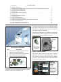
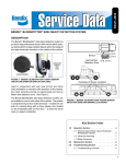
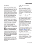
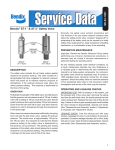
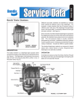
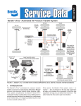
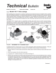
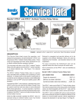
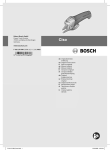
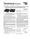
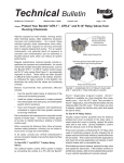
SD-64-4976
®
AutoVue® Lane Departure Warning (LDW) System by Bendix CVS
1.0 DESCRIPTION
1.1 SYSTEM COMPONENTS
The AutoVue Lane Departure Warning (LDW) System by
Bendix CVS gives drivers the ability to combat lane drift
related to: drowsiness/fatigue, distractions, and adverse/
unfavorable weather conditions.
The system components include a digital camera mounted
near the middle of the windshield inside the cab, an enable/
disable switch (typically with status lamps), a driver alert
system (speakers and/or a vibrating seat), and a central
processing unit in the overhead console.
®
At speeds above 37 mph (60 kmph), the AutoVue system
tracks visible lane markings including both solid and dashed
shoulder lines, center lines, and lines between lanes.
When an unexpected lane change takes place – a lane
change without an activated turn signal – the system alerts
the driver to make a correction.
Some vehicles connect the AutoVue system to the vehicle’s
telematics communication system (See Appendix A:
Bendix™ SafetyDirect® system).
The camera is
mounted to the
windshield
The AutoVue LDW system is intended only as an
aid for a conscientious and alert driver. It may not
provide any warning of unintended lane departures
under certain conditions. Do not rely solely on
the system to safely operate the vehicle. It does
not warn of all possible hazards. For example, the
system cannot help prevent an accident if the driver
is impaired or not driving safely.
Ultimate responsibility for the safe operation of the
vehicle remains with the driver at all times.
Vehicle Equipped with AutoVue
LDW System by Bendix CVS
®
FIGURE 1 - AUTOVUE® LDW SYSTEM (BOXES ADDED TO
ILLUSTRATE ACTIVE LANE DETECTION)
Windshield-mounted
Camera
Painted Road Stripes
CAMERA FIELD OF VIEW
NOT TO SCALE
For vehicles traveling above 37 mph (60 kmph), the
GREY area approximates the zone where the system’s
processor is evaluating the vehicle’s positon in the lane.
The rectangles illustrate zones where the
AutoVue LDW system makes specific
measurements about the lane ahead.
FIGURE 2 - AUTOVUE® LDW SYSTEM BY BENDIX CVS - OPERATIONAL VIEW
1
GENERAL SAFETY GUIDELINES
WARNING! PLEASE READ AND FOLLOW THESE INSTRUCTIONS
TO AVOID PERSONAL INJURY OR DEATH:
When working on or around a vehicle, the following guidelines should be observed AT ALL TIMES:
▲ Park the vehicle on a level surface, apply the
parking brakes and always block the wheels.
Always wear personal protection equipment.
▲ Stop the engine and remove the ignition key
when working under or around the vehicle.
When working in the engine compartment,
the engine should be shut off and the ignition
key should be removed. Where circumstances
require that the engine be in operation, EXTREME
CAUTION should be used to prevent personal
injury resulting from contact with moving,
rotating, leaking, heated or electrically-charged
components.
▲ Do not attempt to install, remove, disassemble
or assemble a component until you have read,
and thoroughly understand, the recommended
procedures. Use only the proper tools and
observe all precautions pertaining to use of those
tools.
▲ If the work is being performed on the vehicle’s
air brake system, or any auxiliary pressurized air
systems, make certain to drain the air pressure
from all reservoirs before beginning ANY work
on the vehicle. If the vehicle is equipped with a
Bendix® AD-IS® air dryer system, a Bendix® DRM™
dryer reservoir module, or a Bendix® AD-9si™ air
dryer, be sure to drain the purge reservoir.
▲ F o l l o w i n g t h e v e h i c l e m a n u f a c t u r e r ’s
recommended procedures, deactivate the
electrical system in a manner that safely removes
all electrical power from the vehicle.
▲ Never exceed manufacturer’s recommended
pressures.
▲ Never connect or disconnect a hose or line
containing pressure; it may whip. Never remove
a component or plug unless you are certain all
system pressure has been depleted.
▲ Use only genuine Bendix ® brand replacement
parts, components and kits. Replacement
hardware, tubing, hose, fittings, etc. must be of
equivalent size, type and strength as original
equipment and be designed specifically for such
applications and systems.
▲ Components with stripped threads or damaged
parts should be replaced rather than repaired.
Do not attempt repairs requiring machining or
welding unless specifically stated and approved
by the vehicle and component manufacturer.
▲ Prior to returning the vehicle to service, make
certain all components and systems are restored
to their proper operating condition.
▲ For vehicles with Automatic Traction Control
(ATC), the ATC function must be disabled (ATC
indicator lamp should be ON) prior to performing
any vehicle maintenance where one or more
wheels on a drive axle are lifted off the ground
and moving.
▲ The power MUST be temporarily disconnected
from the radar sensor whenever any tests USING
A DYNAMOMETER are conducted on a Bendix®
Wingman® Advanced™-equipped vehicle.
▲ You should consult the vehicle manufacturer's operating and service manuals, and any related literature,
in conjunction with the Guidelines above.
Due to the inherent limitations of image recognition
technology, the lane departure warning (LDW)
technology — on rare occasions — may not be
able to detect or may misinterpret lane markings.
At these times, alerts may not occur, or erroneous
alerts may occur.
Bendix active and supportive safety technologies,
including AutoVue® LDW, do not replace the need
for safe drivers. No commercial vehicle safety
technology replaces the most important safety
component of all – a skilled, alert professional
driver exercising safe driving habits, as well as
continuous, comprehensive driver training.
IMPORTANT: It is the responsibility of the driver to remain
vigilant and change driving practices depending on traffic
and road conditions.
Ultimate responsibility for the safe operation of the
vehicle remains with the driver at all times.
2
SD SHEET INDEX
1.0Description . . . . . . . . . . . . . . . . . . . . . . . . . . . . . . . . . . . . . . . . . . . . . . 1
1.1 System Components . . . . . . . . . . . . . . . . . . . . . . . . . . . . . . . . . . . . . . . . . 1
2.0 System Operation: What To Expect When Using The AutoVue® LDW System By Bendix CVS . . . 4
2.1 Potential False And Missed Alerts . . . . . . . . . . . . . . . . . . . . . . . . . . . . . . . . . . 5
2.2 Setting Diagnostic Trouble Codes . . . . . . . . . . . . . . . . . . . . . . . . . . . . . . . . . . 5
2.3Maintenance . . . . . . . . . . . . . . . . . . . . . . . . . . . . . . . . . . . . . . . . . . . . . 5
2.4 Camera and ECU Interchangeability . . . . . . . . . . . . . . . . . . . . . . . . . . . . . . . . . 5
2.5 Alert Volume . . . . . . . . . . . . . . . . . . . . . . . . . . . . . . . . . . . . . . . . . . . . . 5
2.6 Windshield Mounting Information . . . . . . . . . . . . . . . . . . . . . . . . . . . . . . . . . . . 6
3.0Troubleshooting . . . . . . . . . . . . . . . . . . . . . . . . . . . . . . . . . . . . . . . . . . . . 7
3.1 General Safety Guidelines . . . . . . . . . . . . . . . . . . . . . . . . . . . . . . . . . . . . . . 7
3.2 Diagnostic Trouble Codes (DTCs) . . . . . . . . . . . . . . . . . . . . . . . . . . . . . . . . . . 7
3.3 Table of AutoVue LDW System Diagnostic Trouble Codes (DTCs) . . . . . . . . . . . . . . . . 7-11
3.4 Advanced Troubleshooting . . . . . . . . . . . . . . . . . . . . . . . . . . . . . . . . . . . . . . 13
3.5 Clearing Diagnostic Trouble Codes (DTCs) . . . . . . . . . . . . . . . . . . . . . . . . . . . . . 14
Appendix A - SafetyDirect® by Bendix CVS . . . . . . . . . . . . . . . . . . . . . . . . . . . . . . . . 15
The system uses speakers to emit a distinctive “rumble
strip” sound on the appropriate side, (or optional vibration
from the left or right portions of the driver’s seat alert if a
non-audible warning is preferred).
The AutoVue LDW system is optimized to reduce false
alarms, however the driver may temporarily use the enable/
disable switch to silence multiple occurrences.
Mounting Bracket
(affixed to the
windshield)
Typical System Components
KeyDescription
1. Lane Departure Warning (LDW) processor
2. Camera with windshield bracket
3. Two 3½-inch speakers with covers (optional)
4. Two vibrating seat motors (optional)
5. Dash-mounted enable/disable switch
3
4
Note: The camera
is removed from the
bracket by sliding
upwards
Camera
Lens
FIGURE 4 - AUTOVUE® CAMERA
The AutoVue LDW system has two lamps: an amber
status lamp, and a green enable/disable lamp. There is
also a switch to permit the driver to temporarily disable
the system. Some vehicles have the lamps and switch
combined. See Figure 5 below.
2
5
1
Green Enable/
Disable Lamp
FIGURE 3 - AUTOVUE® LDW SYSTEM BY BENDIX CVS
See Figure 3 for a list of the typical components used for
AutoVue® LDW systems by Bendix CVS.
Amber Status
Lamp
FIGURE 5 EXAMPLE OF
AN AUTOVUE
SYSTEM
SWITCH.
The design will
vary by vehicle
OEM. The switch
and lamps may
be separate.
3
2.0 SYSTEM OPERATION:
WHAT TO EXPECT WHEN USING THE
AUTOVUE® LDW SYSTEM BY BENDIX CVS
What to Expect in Normal Operating Conditions
Situation
Green
Amber
Typical System Actions
Enable/Disable
Status Lamp
Lamp
Self-test at power-up.
On and remains
illuminated.
On and
remains
illuminated.
Starting the vehicle supplies power to
the system. At start‑up, the system
performs a self-test, then sounds
two chirps through [first the left, then
the right] the speakers. For vehicles
which have systems with vibrating seat
motors, the same sequence is followed
to indicate the system is ready. Once
the vehicle is running and the system is
ready, the green ENABLED lamp and
amber STATUS lamp illuminate.
Driver may test the enable/
disable switch: press ONCE.
Lamp off.
Lamp off.
None.
Driver may test the enable/
Lamp illuminates.
disable switch: press AGAIN.
Lamp
illuminated.
None.
Active system Diagnostic
Trouble Code (DTC) is
present.
Lamp
illuminated.
System disabled.
(Awaits system service)
Vehicle exceeds 37 mph
(60 Kmph), lane markings on
Lamp remains
both sides are being tracked,
illuminated.
and there are no active
system DTCs.
Lamp off.
None. (System is now active).
(With turn signal ON) Driver Lamp remains
changes lanes.
illuminated.
Lamp off.
None.
Lamp remains
illuminated.
Lamp off.
The speaker on the side of the
vehicle towards which it is moving/
drifting will emit a “rumble
strip” sound. (If installed, driver’s
seat vibration will also/instead be
activated.)
Vehicle slows to 37 mph
(60 Kmph), or below, and/or
one or both lane markings
are no longer able to be
tracked by the system.
Lamp remains
illuminated.
Lamp
illuminated.
None (system is NOT active).
Driver temporarily disables
the system by pressing the
disable switch (for example,
construction areas with
poorly marked lines may
cause multiple false alerts.)
Lamp off.
Lamp off.
The system will automatically
re‑enable after 15 minutes.
At
StartUp
On (Without turn signal) Driver
the drifts out of lane/changes
lanes.
Road
Lamp off.
FIGURE 6 - OPERATIONAL SCENARIOS WITH THE AUTOVUE LDW SYSTEM
4
2.1 POTENTIAL FALSE AND MISSED ALERTS
In certain unusual traffic or roadway conditions, the AutoVue® LDW system by Bendix CVS may issue a false alert.
Drivers should take into account the road conditions, and any other factors they are encountering, as they choose how
to react to any alerts they receive from the AutoVue LDW system.
Overview of Potential Issues
Issue
Description
A system Diagnostic
Trouble Code (DTC)
is present.
If the AutoVue LDW system finds a problem at power-up or during operation, it will set a
DTC and will disable the system. The amber lamp will be ON, and the green lamp OFF.
System cannot
discover right and
left lane markings.
•
Mis-installed camera (incorrect placement, not level, loose, etc. See page 6 for full
details of camera installation specifications.) Note: When re-mounting a camera bracket,
use Bendix windshield adhesive ‑ p/n 493088201 ‑ do not use substitutes.
•
Road markings are hard to see (faded/missing lane markings, standing water, snow, or
mud/sand/dirt/debris on the road).
•
Inclement weather (heavy rain, fog, snow, smoke, ice or sleet, etc. is blocking the lane
markings).
•
Camera’s view is not clear (glass not clean, chipped or cracked, not installed where the
windshield wiper cleans the glass, other distortion).
Headlight(s) are not operating or are mis-aimed.
Sun glare or other light source blinds the camera, obscures the lane markings, or makes
other road markings (e.g. tar strips) look like lane markings.
®
Use J1939 detection software to find the DTC code. Go to the Troubleshooting Section
(page 7) to find the recommended repair.
•
•
FIGURE 7 - EXAMPLES OF POTENTIAL ISSUES
NOTE: These are potential situations and responses that might occur when using the AutoVue LDW system. All possible
situations and responses are not covered here.
2.2 SETTING DIAGNOSTIC TROUBLE CODES
The AutoVue LDW system is self-monitored and if any
malfunction is detected, a Diagnostic Trouble Code (DTC)
will be set and the driver will be alerted by the amber status
lamp being illuminated, and the green enabled lamp will
be OFF. See the Troubleshooting Section (page 7), for
more information.
2.3 MAINTENANCE
In normal use, the AutoVue LDW system needs only a
clean, properly maintained windshield to ensure a clear
view of the road ahead.
2.4 CAMERA AND ECU
INTERCHANGEABILITY
AutoVue LDW systems are vehicle make and model
specific. Each part number is customized to a windshield
configuration and offset. When troubleshooting, or when
replacing cameras or Electronic Control Units (ECUs), only
use replacements with the same part number (or a direct
superceding replacement number supplied by Bendix).
2.5 ALERT VOLUME
Audible alert levels are pre-set at the factory and can not
be turned off, nor can the volume be adjusted.
5
2.6 WINDSHIELD MOUNTING INFORMATION
Top of Windshield
Freightliner®
Model
Camera
Location
Code
Argosy
1
Cascadia (AM)
8
Cascadia (OEM)
10
Cent/Col.
1
A
B
Center Line
Vehicle
OEM*
Notch
in the
Camera
Bracket
114SD
Classic XL
FL70
2
M2
4300
8100
8600
9200
International®
2
Left: Use only Bendix windshield
adhesive when re‑mounting
a camera bracket.
9400
9900
Lonestar
Pro Star
Workstar/7000 Series
Kenworth®
Mack®
9
2
T2000
2
T600/800
3
T600/800 Flt Wndshld
7
T660
3
T680
9
T700
2
Pinnacle
Vision
“Torpedo” Level
Rests on the
Bracket Tabs
2
During troubleshooting, if you need to check
that the camera bracket is installed at the
correct point on the windshield, use the
Make/Model columns of the table (left) to
find the Camera Location Code. The second
table (below) shows the correct vertical and
horizontal offset for each Code. Measure
from the notch in the camera bracket to
verify that the location is correct.
Camera
Location
Code
Horizontal
Offset
Vertical
Offset
“A”
“B”
1
9 ± 0.25 in.
2 ± 0.5 in.
2
6 ± 0.25 in.
2 ± 0.5 in.
3
9 ± 0.25 in.
3 ± 0.5 in.
7
7 ± 0.25 in.
3 ± 0.5 in.
8
7 ± 0.25 in.
2 ± 0.5 in.
2
9
6 ± 0.25 in.
2.5 ± 0.5
in.
2
10
8 ± 0.25 in.
2 ± 0.5 in.
378
379
385
386
389
Peterbilt®
340 Car Hauler
2
379 Car Hauler
384/386 with video
384/386 with Curved Windshield
387 (AM)
387 (OEM)
579
Sterling®
Volvo®
Western Star®
A-Line
A-Line Car Hauler
NonVolvo Engine
Volvo Engine
4900
9
2
FIGURE 8 - CORRECT LOCATIONS FOR CAMERA MOUNTING BRACKETS
6
* All trademarks shown here are the property of their
respective owners and are used for reference only.
3.0 TROUBLESHOOTING
3.1 GENERAL SAFETY GUIDELINES
3.2 DIAGNOSTIC TROUBLE CODES (DTCs)
Read and follow the General Safety Guidelines, shown
on page 2 of this document.
Use a J1939 detection software to find the DTC code(s).
IMPORTANT
System Problems. If a problem with the AutoVue® LDW
system by Bendix CVS is detected, it should be serviced
as soon as possible to restore full functionality.
3.3 TABLE OF AUTOVUE® LDW SYSTEM DIAGNOSTIC TROUBLE CODES (DTCS)
Refer to the DTC(s) found and determine the action(s) to take.
Table of Diagnostic Trouble Codes (DTCs), Causes and Recommended Actions
SPN
FMI DTC Name
0084 02
0084 15
0628 31
Vehicle’s
Speed Value
Not Found
Condition Found
The J1939 Data Bus
speed value is not
present.
Suggested Remedial Action(s)
•
Check J1939 Data Bus connection.
•
Is the vehicle’s J1939 Data Bus
functioning?
•
If no problems were found during the
checks above, replace the ECU and
re-test.
•
Check J1939 Data Bus connection.
•
Is the vehicle’s J1939 Data Bus The J1939 Data
Bus speed value is
functioning?
If no problems were found during the within the expected
checks above, replace the ECU and range.
re-test.
Vehicle’s
Speed Value
is Out-ofRange
The J1939 Data Bus
speed value is outside
the expected range.
Bad
Checksum
Value
The internal Electronic
Control Unit (ECU)
checksum does not
•
match the calculated
value.
•
•
0639 02
J1939 Data
Bus Not
Found
Action to Clear
the DTC
The ECU is not
transmitting on the
J1939 Data Bus.
•
Replace the ECU and re-test.
Check for damaged or reversed
J1939 wiring. Check for corroded
or damaged connectors and
loose connections. Using
procedures described by the
vehicle manufacturer, verify the
presence of the J1939 link. Check
for other devices inhibiting J1939
communications.
The J1939 Data
Bus speed value is
present.
A system reset is
required.
The ability to
successfully
transmit on the
J1939 Data Bus.
If no problems were found during the
checks above, replace the ECU and
re-test.
FIGURE 9 - TABLE OF DIAGNOSTIC TROUBLE CODES (PAGES 7-11)
7
Table of Diagnostic Trouble Codes (DTCs), Causes and Recommended Actions
SPN
FMI DTC Name
1703 03
The Right
Speaker is
Shorted to
Power
Condition Found
The resistance from
right speaker positive
or negative output
pins to power input is
less than 10Ω during
sound generation.
Suggested Remedial Action(s)
•
•
•
•
1703 05
1703 06
1704 03
The Right
Speaker Has
an Open
Circuit
The Right
Speaker is
Shorted to
Ground
The Left
Speaker is
Shorted to
Power
Resistance between
right speaker output
pins is greater than
40Ω during sound
generation.
Resistance between
right speaker positive
or negative output
pins and ground is
less than 10Ω during
sound generation.
OR
Resistance between
right speaker positive
and negative output
pins is less than
7Ω during sound
generation.
Resistance from left
speaker positive or
negative output pins
to power input is
less than 10Ω during
sound generation.
•
•
•
•
•
•
•
•
Check the wiring between the right
speaker and ECU.
Test by temporarily installing a known
good speaker in the right speaker
location.
If no problems were found with the
wiring, and the test with a good
speaker did not solve the problem,
replace the ECU and re-test.
A system reset
is required, and
the resistance
from right speaker
positive or negative
output pins to
power input needs
to be greater than
10Ω during sound
generation.
Check the wiring between the right
speaker and ECU.
Test by temporarily installing a known
good speaker in the right speaker
location.
If no problems were found with the
wiring, and the test with a good
speaker did not solve the problem,
replace the ECU and re-test.
System reset and
the resistance
between right
speaker output
pins is less than
40Ω during sound
generation.
System reset and
the resistance
between right
speaker positive
or negative output
pins and ground
Check the wiring between the right
is greater than
speaker and ECU.
Test by temporarily installing a known 10Ω during sound
generation.
good speaker in the right speaker
location.
OR
If no problems were found with the
System reset and
wiring, and the test with a good
the resistance
speaker did not solve the problem,
between right
replace the ECU and re-test.
speaker positive
and negative
output pins is
greater than 7Ω
during sound
generation.
Check the wiring between the left
speaker and ECU.
Test by temporarily installing a known
good speaker in the left speaker
location.
If no problems were found with the
wiring, and the test with a good
speaker did not solve the problem,
replace the ECU and re-test.
FIGURE 9 - TABLE OF DIAGNOSTIC TROUBLE CODES (PAGES 7-11)
8
Action to Clear
the DTC
System reset and
the resistance
from left speaker
positive or
negative output
pins to power input
is greater than
10Ω during sound
generation.
Table of Diagnostic Trouble Codes (DTCs), Causes and Recommended Actions
SPN
FMI DTC Name
Condition Found
Suggested Remedial Action(s)
•
1704 05
1704 06
The Left
Speaker Has
an Open
Circuit
The Left
Speaker is
Shorted to
Ground
Resistance between
left speaker output
pins is greater than
40Ω during sound
generation.
Resistance between
left speaker positive
or negative output
pins and ground is
less than 10Ω during
sound generation.
OR
Resistance between
left speaker positive
and negative output
pins is less than
7Ω during sound
generation.
•
•
•
•
•
Check the wiring between the left
speaker and the ECU.
Test by temporarily installing a known
good speaker in the left speaker
location.
If no problems were found with the
wiring, and the test with a good
speaker did not solve the problem,
replace the ECU and re-test.
Action to Clear
the DTC
System reset and
the resistance
between left
speaker output
pins is less than
40Ω during sound
generation.
System reset and
the resistance
between left
speaker positive
or negative output
pins and ground
Check the wiring between the left
is greater than
speaker and ECU.
Test by temporarily installing a known 10Ω during sound
generation.
good speaker in the left speaker
location.
OR
If no problems were found with the
System reset and
wiring, and the test with a good
the resistance
speaker did not solve the problem,
between left
replace the ECU and re-test.
speaker positive
and negative
output pins is
greater than 7Ω
during sound
generation.
FIGURE 9 - TABLE OF DIAGNOSTIC TROUBLE CODES (PAGES 7-11)
9
Table of Diagnostic Trouble Codes (DTCs), Causes and Recommended Actions
SPN
FMI DTC Name
Condition Found
Suggested Remedial Action(s)
•
•
•
•
•
1705 02
The Turn
Signal Input
Remains
High
Turn signal input is
stuck at high level
for more than three
(3) seconds
•
•
1705 03
The Input
Voltage is
Too High
Input voltage is above
16V
•
•
Check the wiring between the
Electronic Control Unit (ECU) and
the turn signal.
Verify that the common wire of the
turn signal/brake lamp circuit was not
used.
Replace any non-functioning turn
signal bulb(s).
Test by temporarily installing a known
good turn signal flasher.
Connect a test lamp or multi-meter
to the turn signal wires one at a time
(orange for left, white for right) and
notice the state of the test lamp or
the voltage readout on the multimeter. With the ignition on, test and
observe the following.
1. Readings should be off or 0v when
the turn signal is off.
Turn signal input
2. Readings should pulse to 12V is low for three
when the turn signal is on.
(3) seconds.
3. If the signal pulses with both turn
signals, turn the signal off before
continuing.
4. Readings should be 0V when the
service brake pedal is applied.
5. Readings should be 0V when the
parking brake is disengaged.
6. Readings should be 0V when the
headlights are ON.
If the turn signal circuit does not pass
any of the above tests you must
relocate the turn signal connection.
If no problems were found with the
wiring/bulbs, and the test with a
good signal flasher did not solve
the problem, replace the ECU and
re-test.
Measure the ignition voltage. Ensure
that ignition voltage is not greater
than 16 VDC. Check the vehicle
battery and associated components.
Inspect for damaged wiring,
Input voltage is
damaged or corroded connectors
and loose connections. Check the
below 16V.
wiring between the ignition and the
ECU.
If no problems were found during the
checks above, replace the ECU and
re-test.
FIGURE 9 - TABLE OF DIAGNOSTIC TROUBLE CODES (PAGES 7-11)
10
Action to Clear
the DTC
Table of Diagnostic Trouble Codes (DTCs), Causes and Recommended Actions
SPN
FMI DTC Name
Condition Found
Suggested Remedial Action(s)
•
•
1705 04
The Input
Voltage is
Too Low
Input voltage is below
9.5V
•
•
1705 05
The Enabled Resistance from
enabled or status
Lamp or
Status Lamp output to ground is
Output Open greater than 140KΩ
while output is not
energized.
•
•
•
Action to Clear
the DTC
Check the ignition voltage.
Measure the ignition voltage under
load. Ensure that the ignition voltage
is greater than 10 VDC (volts DC).
Check the vehicle battery and
associated components. Inspect
for damaged wiring, damaged or
Input voltage is
corroded connectors and loose
above 9.5V.
connections. Check the condition of
the fuse.
Check the wiring between the ignition
and the ECU.
If no problems were found during the
checks above, replace the ECU and
re-test.
Check the wiring between the ECU
and the switch or status lamp.
Test by temporarily installing a known
good switch/status lamp.
If no problems were found with the
wiring, and the test with a good
switch/status lamp did not solve the
problem, replace the ECU and retest.
Resistance from
enabled or status
output to ground is
less than 140KΩ
while output is not
energized.
(Note: the green “enabled” lamp output will not illuminate if this DTC is present)
1705 06
Enabled
Lamp or
Status Lamp
Output Short
to Power
•
Current into enabled
or status output pin
is greater than 4.5A
while the output is
energized.
•
•
Check the wiring between the ECU
and the switch or status lamp.
Test by temporarily installing a known
good switch/status lamp.
If no problems were found with the
wiring, and the test with a good
switch/status lamp did not solve the
problem, replace the ECU and retest.
System reset and
current into enable
or status output
is less than 4.5A
while the output is
energized.
(Note: the green “enabled” lamp output will not illuminate if this DTC is present)
•
•
1705 31
Internal
Failure
Internal failure
•
Check the camera cable.
Test by temporarily installing a known
good camera.
Internal failure
If no problems were found with
clears
the cable and the test with a good
camera did not solve the problem,
replace the ECU and re-test.
For all other DTCs, or problems after re-testing a replacement ECU, contact the Bendix Tech Team.
For direct telephone technical support, the Bendix Tech Team is available at 1-800-AIR-BRAKE (1-800-247-2725,
option 2) Monday through Friday, 8:00 a.m. to 6:00 p.m. ET. Follow the instructions in the recorded message.
The Bendix Tech Team can also be reached by e-mail at: [email protected].
FIGURE 9 - TABLE OF DIAGNOSTIC TROUBLE CODES (PAGES 7-11)
11
AutoVue®
Processor
AutoVue®
Camera
Mating Connector
8
7
3
9
6
5
4
3
2
1
4
5
6
7
Option Audio
11
10
9
8
7
6
5
4
3
2
1
Brown
8
Blue
Blue/White
+
-
25W
Lane Departure (LDW) Warning Options
12
10
2
B
11
1
A
12
+
25W
+
-
Overhead
Harness
Option Haptic
Pink
-
L
+
Red
+
Brown
-
R
+
Orange
White
Purple
Blue
Ignition ON: Range (3.2V - 3.6V) tested to chassis ground
Black
Orange
Yellow
(Where Used)
RS-232 Telematics
Connector
Grey
+
R
11
9
1
4
12
10
Switch
2
Test to
ground
Black
Suppressions/Lamps
Turn Signals / Dash Switch
Ground
Red
Ignition 12v
Red/Yellow
Yellow
Battery 12v
J1939
Green
FIGURE 10 - AUTOVUE® LDW SYSTEM BY BENDIX CVS - WIRING DIAGRAM
12
3.4 ADVANCED TROUBLESHOOTING
Refer to the AutoVue® LDW system by Bendix CVS wiring
diagram on page 12, during these procedures.
General. Inspect the camera and its lens, for any damage
and the wiring for any pinching or cuts. If a camera bracket
appears to have been reinstalled, check if the bracket is
level by removing the camera (slide upwards), and use
a torpedo level on the bracket tabs (See Figure 8, on
page 6). Note that the other vehicle cab accessories
must be carefully installed since mounting screws, etc.
that penetrate locations where the AutoVue components
or wiring are routed can cause shorts or wiring breaks.
If you do not have the capability to read the J1939 error
codes it is recommended to, in turn swap out components
with known good system components in the following order:
switch; processor; camera.
In practice this would result in:
•
•
•
Temporarily replace the switch with a known good
switch, retest. If this does not correct the problem put
the original switch back in.
Temporarily replace the processor box with a known
working unit. If this does not correct the problem put
the original box back in.
Temporarily replace the camera with a known working
unit. If this does not correct the problem put the original
camera back in.
If after temporarily replacing all the major components the
green lamp still fails to illuminate, hardware issues have
been eliminated and the technician can focus elsewhere
(wiring, mis-installation, etc.) for the source of the problem.
Confirm the processor part number:
Potentially a processor may have been programmed for
one vehicle model but was mis-installed or moved to a
different vehicle model. Call Bendix to verify that you
have the correct processor part number on the vehicle.
In cases where — after start-up — an Enable/Disable
switch is pressed but the “enable” (green) and “status”
(amber) lamps remain on:
1. Conditions: Vehicle parked, with the ignition on. Using
a voltmeter connect the positive (+) lead to gray wire
and the negative lead (-) to a good chassis ground, do
not use the black wire on switch for ground.
2. The voltage reading should be between 3.2 V to 3.6 V.
3. Using a voltmeter connect the positive (+) lead to the
switch pin black wire and the negative lead (-) to a
good chassis ground.
4. The voltage reading should be between -0.10 V to
0.1 V.
5. If the above voltages are not correct, turn off the ignition
and remove the switch from the switch socket.
6. Using an Ohmmeter, connect the positive (+) lead
to the gray wire, and the negative lead (-) to a good
chassis ground, do not use the black wire.
7. The resistance reading should be between 30k Ohms
and 70k Ohms.
8. If the resistance reading is less than 30k Ohms,
disconnect the main connector from the processor
and recheck the resistance of the gray wire. If the
resistance is still less than 30k Ohms, then a short
may exist in the wiring harness (for example, a screw
may have been driven in to the wire).
9. If the resistance reading is greater than 70k Ohms, an
open circuit may exist in the wiring harness.
10. Using an Ohmmeter, connect the positive (+) lead
to the black wire and the negative lead (-) to a good
chassis ground.
11. The resistance reading should be less than one (1) Ohm.
12. If the resistance reading is greater than one (1) Ohm,
an open circuit may exist in the wiring harness.
13. If the above voltages are correct, turn off the ignition
and remove the switch from the switch socket.
14. Using an Ohmmeter, connect the positive (+) lead to
blue wire and the negative lead (-) to a good chassis
ground, do not use the black wire.
15. The resistance reading should be greater than
10k Ohms.
16. Using an Ohmmeter, connect the positive (+) lead to
violet wire and the negative lead (-) to a good chassis
ground, do not use the black wire.
17. The resistance reading should be greater than
10k Ohms.
In cases where — after start-up — an Enable/Disable
switch is pressed but the “enable” (green) lamp remains
on and the “status” (amber) lamp does not remain on:
1. Conditions: Vehicle parked, with the ignition on, and
all LDW components (camera, processor, & switch)
are connected.
2. Turn off the ignition and remove the switch from the
switch socket.
3. Using an Ohmmeter, connect the positive (+) lead to
blue wire and the negative lead (-) to a good chassis
ground, do not use the black wire.
4. The resistance reading should be greater than 10k
Ohms.
13
5. If the resistance is less than 10k Ohms, then disconnect
the main connector from the processor and recheck
the resistance on the blue wire. If the resistance is
still less than 10k Ohms then a short may exist in the
wiring harness (a screw may have been driven in to
the wire). If the resistance is greater than 10k Ohms
then temporarily replace the processor with a known
good unit and re-test.
3.5 CLEARING DIAGNOSTIC
TROUBLE CODES (DTCS)
Once the problem has been found and resolved, clear the
AutoVue® LDW system Diagnostic Trouble Codes (DTCs)
by cycling the ignition power.
6. Reconnect the main connector to the processor
and recheck the resistance on the blue wire. If the
resistance is greater than 10k Ohms then temporarily
replace the processor with a known good unit and
re-test
ADDITIONAL SUPPORT AT
WWW.BENDIX.COM/1‑800‑AIR‑BRAKE (1‑800‑247-2725, OPTION 2)
For the latest information, and for free downloads of the Bendix® ACom® Diagnostics
software, and its User Guide, visit the Bendix website at: www.bendix.com.
For direct telephone technical support, the Bendix Tech Team is available at 1-800-AIRBRAKE (1-800-247-2725, option 2) Monday through Friday, 8:00 A.M. to 6:00 P.M. ET.
Follow the instructions in the recorded message.
The Bendix Tech Team can also be reached by e-mail at: [email protected].
14
APPENDIX A - SAFETYDIRECT® BY BENDIX CVS
Appendix A
SafetyDirect® by Bendix CVS
SAFETYDIRECT® FUNCTION
When the SafetyDirect function is enabled, the AutoVue® LDW system processor has the ability to collect relevant
driver and vehicle performance data via the LDW system and the J1939 CAN Bus. When a trigger event occurs,
vehicle data and, in some cases, video, is saved in the system for later download via the vehicle telematics system.
In-Vehicle
Hardware
J1939
Data Link
AutoVue®
Processor
Telematics Provider On Board
Computer (OBC)
Telematics Antenna
AutoVue®
Camera
Optional Data Path
Network
SafetyDirect® Web Portal
SafetyDirect®
Servers
Telematics
Servers
Over the Air Provider
FIGURE 11 - AUTOVUE® LDW SYSTEM COMMUNICATION WITH SAFETYDIRECT® BY BENDIX CVS
Appendix A
15
Log-on and Learn from the Best
On-line training that's available when you are
Visit www.brake-school.com.
24/7/365.
Trademark acknowledgements:
Any references in this manual to FREIGHTLINER, INTERNATIONAL, KENWORTH, MACK, PETERBILT,
STERLING, VOLVO, WESTERN STAR, and any other company or trademark are solely for identification
and cross reference purposes. The trademarks are the property of their respective companies and are
not affiliated with or endorsing Bendix Commercial Vehicle Systems LLC. Bendix Commercial Vehicle
Systems LLC does not represent any parts shown as products manufactured or remanufactured by the
companies so named herein.
SD-64-4976 © 2014 Bendix Commercial Vehicle Systems LLC, a member of the Knorr-Bremse Group. All Rights Reserved. 11/14
16