1
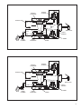
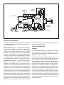
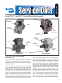
SD-13-4793
Bendix® M-21™ and M-22™ AntiLock Modulator Assembly
SUPPLY
SOLENOID
CONNECTOR
SUPPLY
DELIVERY
(CAST-IN ID #2)
DELIVERY
(CAST-IN ID #2)
EXHAUST
(CAST-IN ID #3)
DELIVERY
SUPPLY
(CAST-IN ID #1)
DELIVERY
SUPPLY
(CAST-IN ID #1)
SOLENOID
CONNECTOR
MOUNTING
HOLES
MOUNTING
HOLES
EXHAUST
(CAST-IN ID #3)
M-21™ MODULATOR
M-22™ MODULATOR
FIGURE 1 - M-21™ AND M-22™ MODULATOR
DESCRIPTION
There are two Bendix antilock modulators available from
Bendix Commercial Vehicle Systems LLC, the older M-21™
modulator and the newer M-22™ modulator. Both are
functionally the same.
The M-21™ and M-22™ antilock system modulators (Figure
1) are essentially high capacity, on/off air valves that
incorporate a pair of electrical solenoids for control. The
solenoids provide the electro-pneumatic interface or link
between the antilock controller electronics and the air brake
system. The modulator can be used to control the braking
function on an individual wheel or two service actuators.
When used to control both service chambers on an axle
or two chambers on the same side of a tandem axle, the
modulator is sometimes mounted ahead of a quick release
valve, which provides quick exhaust of service applications
during normal braking. (Figure 2) In the case of individual
wheel control applications, the modulator is always the
last control valve through which air passes on its way
to the service brake actuator and a solenoid assembly
which contains one normally open solenoid (NOS), one
normally closed solenoid (NCS), and two inlet and exhaust
diaphragm valves. A Packard, three pin, 280 series weather
resistant electrical connector is an integral part of the
modulator solenoid assembly and serves to carry control
commands from the antilock controller to the modulator.
Two, .35 inch diameter, mounting holes are provided for
frame or cross member mounting. The single supply,
delivery and exhaust port on both modulators is identified
with a cast, embossed numeral for positive identification.
1
FRONT AXLE SYSTEMS
WHEEL CONTROL
REAR AXLE SYSTEM
AXLE CONTROL
WHEEL CONTROL
TO
ANTILOCK
CONTROLLER
TO
ANTILOCK
CONTROLLER
TO
ANTILOCK
CONTROLLER
M-21™ OR M-22™ MODULATOR
M-21™ OR M-22™
MODULATOR
CONTROLLER/
RELAY ASSEMBLY
QUICK RELEASE VALVE
M-21™ OR M-22™
MODULATOR
M-21™ OR M-22™ MODULATOR
QUICK RELEASE VALVE
M-21™ OR M-22™ MODULATOR
TO ANTILOCK
CONTROLLER
TO
ANTILOCK
CONTROLLER
bw
SERVICE BRAKE
CHAMBER
SERVICE BRAKE
CHAMBER
SERVICE &
SPRING BRAKE
CHAMBER
FIGURE 2 - WHEEL AND AXLE CONTROL SYSTEMS
They are as follows;
Identification
1
2
3
Air Line Connection
Supply
(incoming air from foot valve or relay)
Delivery
(air delivery to service actuators)
Exhaust
(air exhaust during antilock control)
OPERATION
NON-ANTILOCK APPLICATION (FIGURE 3)
During normal non-antilock braking, both solenoids are
de-energized (no electrical power). Brake application air
enters the supply port of the modulator and flows to, and
through, the open exhaust solenoid then to the exhaust
diaphragm. Air pressure, along with spring force, seats
the exhaust diaphragm on the exhaust passage thus
preventing the escape of service air. Simultaneously,
application air flows to the supply diaphragm and forces it
away from its seat. Air flows past the open supply and out
the modulator delivery port to the service brake chambers.
2
NON-ANTILOCK HOLD (FIGURE 4)
When the desired air pressure is attained in the service
brake chambers, the brake system is in the holding position.
In the holding position both solenoids in the modulator
remain de-energized and the balance of the internal
components remain in the same position as they assumed
during application.
EXHAUST
DIAPHRAGM
EXHAUST
SOLENOID
EXHAUST PORT
BRAKE VALVE
SUPPLY
SOLENOID
BRAKE
CHAMBER
SUPPLY
DIAPHRAGM
SPRING
SPRING
FIGURE 3 - M-21™, M-22™ MODULATOR NON-ANTILOCK APPLICATION OF SERVICE BRAKES
EXHAUST
DIAPHRAGM
EXHAUST
SOLENOID
EXHAUST PORT
BRAKE VALVE
SUPPLY
SOLENOID
BRAKE
CHAMBER
SUPPLY
DIAPHRAGM
SPRING
SPRING
FIGURE 4 - M-21™, M-22™ MODULATOR NON-ANTILOCK APPLICATION HELD POSITION
3
EXHAUST
DIAPHRAGM
EXHAUST
SOLENOID
EXHAUST PORT
BRAKE VALVE
SUPPLY
SOLENOID
BRAKE
CHAMBER
SUPPLY
DIAPHRAGM
SPRING
SPRING
FIGURE 5 - M-21™, M-22™ MODULATOR NON-ANTILOCK EXHAUST OF SERVICE BRAKES (NORMAL)
NON-ANTILOCK EXHAUST
The manner in which air exhausts through the modulator
differs, depending upon how rapidly the brake application
is released by the driver.
Normal Exhaust (Figure 5) - During a normal, relatively
"slow", brake release, air moves back through the
modulator in the reverse direction as it flowed during
application. The internal components of the modulator
will remain in the same position as they assumed during
application until air pressure decreases to approximately
one half psi, at which time the supply diaphragm will seat on
the supply passage. Air will generally not be expelled from
the modulator exhaust port during normal brake release.
Rapid Exhaust (Figure 6) - The rapid exhaust operation
described in the following text only occurs when the
modulator is controlling two type 30 (or larger) service
chambers. During a very rapid brake release the modulator
will exhaust air in a different manner. An example of this
would be the case if the driver made a severe brake
application then lifted his foot from the foot valve. During
a rapid brake release, air from the exhaust diaphragm
flows back through the open exhaust solenoid and to the
application device's exhaust. With pressure removed from
the control side of the exhaust diaphragm, air, returning to
the modulator from the service chambers, lifts the exhaust
diaphragm from its seat. Returning air flows past the open
exhaust and out the modulator exhaust port. Air will also
4
flow past the open supply diaphragm and back to the
application device's exhaust.
ANTILOCK OPERATION
GENERAL
If a service brake application is made and the antilock
system detects an impending wheel lockup, the antilock
controller will immediately begin modification of the brake
application using the modulator.
In order to modify the brake application, the coils of the two
solenoid valves contained in the modulator are energized
or de-energized in a pre programmed sequence by the
antilock controller. When a solenoid coil is energized, a
shuttle within the solenoid moves, and depending upon
the function of the specific solenoid, it either opens or
closes thereby causing the exhaust or re-application of
air pressure to the brake actuator. The solenoids in the
modulator are controlled independently by the antilock
controller. By opening and closing the solenoid valves in
the modulator, the antilock controller is able to simulate
what the driver does when he "pumps the brakes". It must
be remembered, however, that unlike the driver the antilock
controller is able to "pump" each modulator, along with the
brakes connected to it, independently and with far greater
speed and accuracy.
EXHAUST
DIAPHRAGM
EXHAUST
SOLENOID
EXHAUST PORT
BRAKE VALVE
SUPPLY
SOLENOID
BRAKE
CHAMBER
SUPPLY
DIAPHRAGM
SPRING
SPRING
FIGURE 6 - M-21™, M-22™ MODULATOR NON-ANTILOCK EXHAUST OF SERVICE BRAKES (RAPID)
ANTILOCK EXHAUST (FIGURE 7)
ANTILOCK HOLD
When wheel lock is detected, or imminent, the antilock
controller simultaneously energizes both the supply and
exhaust solenoids in the modulator. Energizing the supply
solenoid causes its exhaust to close and inlet to open.
With the inlet of the supply solenoid open, application
air is permitted to flow to the control side of the supply
diaphragm. Air pressure acting on the supply diaphragm
causes it to close the supply and prevent further delivery
of air to the brake chamber.
The antilock controller will place the modulator in the
hold position when it senses that the correct wheel speed
(braking force) has been attained. The antilock controller
will also place the modulator in the hold position, prior
to entering the re-apply, when it detects recovery from
a locked wheel condition. In this mode of operation the
modulator supply solenoid remains energized while the
exhaust solenoid is de-energized. De-energizing the
exhaust solenoid opens its inlet and closes its exhaust.
Opening the exhaust solenoid inlet, allows application air to
flow to the control side of the exhaust diaphragm which then
seals the exhaust passage. With the exhaust diaphragm
seated, further exhaust of brake chamber air pressure is
prevented. Because the supply solenoid remains energized
the supply diaphragm remains seated, thus preventing
application air from flowing to the delivery port and out to
the brake chamber. The modulator can enter the antilock
exhaust or re-apply mode from the antilock hold mode.
Energizing the exhaust solenoid closes its inlet and
opens its exhaust. By closing the exhaust solenoid inlet,
application air is prevented from flowing to the control side
of the exhaust diaphragm. Air pressure, which was present
on the control side of the exhaust diaphragm flows out the
exhaust port of the modulator. With control air pressure
removed from the exhaust diaphragm, brake application
air forces the exhaust diaphragm to unseat which allows
it to flow out the modulator exhaust port. The modulator
will remain in the antilock exhaust mode until the antilock
controller senses that wheel speed has increased. The
modulator can enter the antilock hold or re-apply mode
from the antilock exhaust mode.
5
EXHAUST
DIAPHRAGM
EXHAUST
SOLENOID
EXHAUST PORT
BRAKE VALVE
SUPPLY
SOLENOID
BRAKE
CHAMBER
SUPPLY
DIAPHRAGM
SPRING
SPRING
FIGURE 7 - M-21™, M-22™ MODULATOR ANTILOCK EXHAUST OF BRAKES
ANTILOCK RE-APPLY
If the antilock controller senses that wheel speed has
increased sufficiently to require reapplication of braking
pressure, it de-energizes the supply and exhaust solenoids.
With both solenoids de-energized, the modulator re-applies
air to the brakes in the same manner it did during a nonantilock application.
PREVENTIVE MAINTENANCE
GENERAL
Perform the tests and inspections presented at the
prescribed intervals. If the modulator fails to function as
described, or leakage is excessive, it should be replaced
with a new or genuine Bendix remanufactured unit,
available at any authorized parts outlet.
EVERY 3 MONTHS, 25,000 MILES OR 900
OPERATING HOURS
1. Remove any accumulated contaminates and visually
inspect the exterior for excessive corrosion and physical
damage.
2. Inspect all air lines and wire harnesses connected to
the modulator for signs of wear or physical damage.
Replace as necessary.
6
3. Test air line fittings for excessive leakage and tighten
or replace as necessary.
4. Perform the ROUTINE OPERATION AND LEAKAGE
TESTING described in this manual.
OPERATION & LEAKAGE TESTS
LEAKAGE TESTING
1. Park the vehicle on a level surface and block or chock
the wheels. Release the parking brakes and build the
air system to full pressure.
2. Turn the engine OFF and make 4 or 5 brake applications and note that the service brakes apply and release
promptly.
3. Build system pressure to governor cut-out and turn the
engine OFF.
4. Make and hold a full service brake application.
A. Apply a soap solution to the exhaust port of the
modulator. Leakage should not exceed a 1" bubble in
less than 3 seconds. If leakage exceeds the specified
maximum, replace the modulator.
B. Apply a soap solution around the solenoid assembly
(top and bottom). Leakage should not exceed a 1"
bubble in less than 3 seconds. If leakage exceeds the
specified maximum, tighten the solenoid cap screws
and re-test. If the leakage remains excessive after retesting, replace the modulator.
C. Apply a soap solution around each diaphragm cover.
Leakage should not exceed a 1" bubble in less than 3
seconds. If leakage exceeds the specified maximum,
tighten the diaphragm cap screws and re-test. If the
leakage remains excessive after re-testing, replace
the modulator.
OPERATION TESTING
To properly test the function of the modulator will require
2 service technicians.
VALVE REMOVAL
1. Park the vehicle on a level surface and block the wheels
and/or hold the vehicle by means other than the air
brakes.
2. Drain the air pressure from all vehicle reservoirs.
3. Identify and mark or label all air lines and their
respective connections on the valve to facilitate ease
of installation.
4. Disconnect both air lines and the electrical connector.
5. Remove the valve from the vehicle.
1. Park the vehicle on a level surface and block or chock
the wheels. Release the parking brakes and build the
air system to governor cut out.
VALVE INSTALLATION
2. Turn the engine ignition key to the OFF position then
make and hold a full brake application.
1. Install all air line fittings and plugs making certain thread
sealing material does not enter the valve.
3. With the brake application held and a service
technicians posted at one of the modulators, turn the
vehicle ignition key to the ON position. ONE OR TWO
SHORT bursts of air pressure should be noted at the
modulator exhaust. Repeat the test for each modulator
on the vehicle. If at least a single burst of exhaust is not
noted or the exhaust of air is prolonged and not short,
sharp and well defined, perform the Electrical Tests.
2. Install the assembled valve on the vehicle.
ELECTRICAL TESTS
1. Before testing the solenoid assembly of a "suspect"
modulator, its location on the vehicle should be
confirmed using the Trouble Shooting or Start Up
Procedure for the specific antilock controller in use.
(See the Service Data Sheet for the antilock controller
for this procedure.)
2. Proceed to the modulator in question and inspect its
wiring connector. Disconnect the connector and test the
resistance between the pins ON THE MODULATOR.
Refer to figure 9.
A. HOLD to SOURCE: Read 3.5 to 5 OHMS
3. Reconnect both air lines to the valve using the
identification made during VALVE REMOVAL step 3.
4. Reconnect the electrical connector to the modulator.
5. After installing the valve, test all air fittings for excessive
leakage and tighten as needed.
M-21™ MODULATOR TECHNICAL INFORMATION
Porting -
1 Supply Port (from
brake, relay or quick
release valve)
1 Delivery Port (brake
actuator)
Solenoid Voltage -
12 Volts DC Nominal
Maximum Operating Pressure - 150 psi Gauge
Operating Temp. Range -
-40 to +185 Fahrenheit
Pressure Differential -
1 psi maximum
B. EXHAUST to SOURCE: Read 3.5 to 5 OHMS
C. EXHAUST to HOLD: Read 7 to 10 OHMS
D. Individually test the resistance of each pin to vehicle
ground and note there is NO CONTINUITY.
If the resistance readings are as shown, the wire
harness leading to the modulator may require repair or
replacement. Before attempting repair or replacement
of the wire harness, refer to the test procedures
specified for the antilock controller in use for possible
further testing that may be required to substantiate the
wire harness problem. If the resistance values are NOT
AS SHOWN ABOVE, replace the modulator.
7
EXHAUST
DIAPHRAGM
EXHAUST
SOLENOID
EXHAUST PORT
BRAKE VALVE
SUPPLY
SOLENOID
BRAKE
CHAMBER
SUPPLY
DIAPHRAGM
SPRING
SPRING
FIGURE 8 - M-21™, M-22™ MODULATOR ANTILOCK APPLICATION HELD POSITION
CONNECTOR
CONNECTOR
SOURCE
EXHAUST
HOLD
SOURCE
EXHAUST
M-21™ MODULATOR
FIGURE 9 - M-21™, M-22™ MODULATOR CONNECTOR VIEW
8
HOLD
M-22™ MODULATOR
9
10
11
12
BW1664 © 2010 Bendix Commercial Vehicle Systems LLC All rights reserved. 6/2010 Printed in U.S.A.