1
SD-08-2412
®
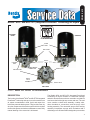
Bendix® AD-9® and AD-9® IPC (Integrated PuraGuard® Coalescing) Air Dryers
EXTENDED
PURGE
STANDARD
IPC AIR DRYER LABEL
OUTER
SHELL
END COVER
SUPPLY
PORT
CONTROL
PORT
DELIVERY PORT
WIRING HARNESS
CONNECTION
PURGE VALVE
CHECK
VALVE
ASSEMBLY
SAFETY VALVE
END COVER
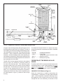
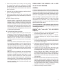
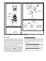
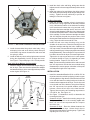
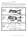
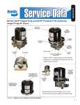
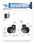
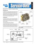
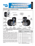
FIGURE 1 - BENDIX® AD-9® AND AD-9® IPC AIR DRYER MODELS
DESCRIPTION
The function of the Bendix® AD-9® and AD-9® IPC Integrated
PuraGuard® Coalescing air dryers is to collect and remove
air system contaminants in solid, liquid, and vapor form
before they enter the brake system. They provide clean, dry
air to the components of the brake system which increases
the life of the system and reduces maintenance costs. Daily
manual draining of the reservoirs is eliminated.
The Bendix AD-9 and AD-9 IPC Integrated PuraGuard
Coalescing air dryers consists of a desiccant cartridge
and a die cast aluminum end cover secured to a cylindrical
steel outer shell with eight cap screws and nuts. The end
cover contains a check valve assembly, a safety valve,
three threaded air connections, and the purge valve
housing assembly. The removable purge valve housing
assembly incorporates a purge valve mechanism and a
turbocharger cut-off feature that is designed to prevent loss
1
CHECK
VALVE
ORIFICE
DESICCANT
CARTRIDGE
DESICCANT
BED
RESERVOIR
PURGE
VALVE
SUPPLY
PORT
ENGINE
TURBO
COMPRESSOR
GOVERNOR
CONTROL
PORT
OIL
SEPARATOR
PURGE
VOLUME
SUMP
EXHAUST
CHECK
VALVE
ASSEMBLY
DELIVERY
PORT
HEATER
ELEMENT
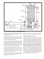
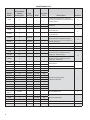
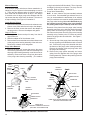
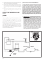
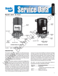
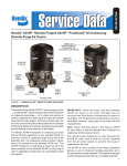
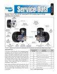
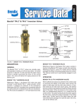
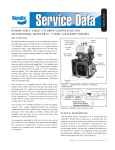
FIGURE 2 - BENDIX® AD-9® AND AD-9® IPC AIR DRYER CHARGE CYCLE
of engine “turbo” boost pressure during the purge cycle of
the Bendix® AD-9® and AD-9® IPC air dryers. For ease of
serviceability, the desiccant cartridge and discharge check
valve assembly are screw-in type. The purge valve housing
assembly – which includes the heater and thermostat
assembly – and the discharge check valve assembly are
serviceable from the exterior of the air dryer, while servicing
the screw-in desiccant cartridge requires removal of the air
dryer assembly from the vehicle.
The AD-9 IPC air dryer appears identical to the standard
AD-9 air dryer, but contains a coalescing media at
the inlet of the desiccant bed. This coalescing media
provides a higher level of oil removal over the standard
AD-9 air dryer. The AD-9 IPC air dryer has all the same
functions of the standard AD-9 air dryer, and is used
where oil is contaminating downstream components.
The Bendix AD-9 IPC air dryer can be identified by the
IPC label (shown in Figure 1), located on the air dryer
housing.
2
The Bendix AD-9 and AD-9 IPC air dryers have three
female pipe thread air connections and each is identified
as follows:
Port l.D.
Function/Connection
CON 4................Control Port
(purge valve control and turbo cut-off)
SUP 11 .............Supply Port (air in)
DEL 2 ...............Delivery Port (air out)
OPERATION OF THE BENDIX AD-9 AIR
DRYER
The AD-9 and AD-9 IPC air dryers alternate between two
operational modes, or “cycles”, during operation: the charge
cycle and the purge cycle. The following description of
operation is separated into these “cycles” of operation.
CHARGE CYCLE (Refer to Figure 2)
When the compressor is loaded (compressing air)
compressed air – along with oil, oil vapor, water and water
vapor – flows through the compressor discharge line to
the supply port of the air dryer end cover. As air travels
through the end cover assembly, its direction of flow
CHECK
VALVE
ORIFICE
PURGE
VOLUME
OIL
SEPARATOR
CONTROL
PORT
COMPRESSOR
GOVERNOR
DESICCANT
BED
DESICCANT
CARTRIDGE
SUPPLY
PORT
RESERVOIR
TURBO
CUT-OFF
PISTON
PURGE
VALVE
ENGINE
TURBO
EXHAUST
HEATER
ELEMENT
CHECK
VALVE
ASSEMBLY
DELIVERY
PORT
SUMP
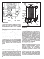
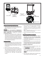
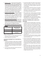
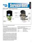
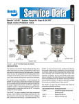
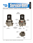
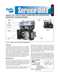
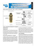
FIGURE 3 - BENDIX®AD-9® AND AD-9® IPC AIR DRYER PURGE CYCLE
changes several times, reducing the temperature, causing
contaminants to condense and drop to the bottom, or sump,
of the air dryer end cover.
The air dryer will remain in the charge cycle until air brake
system pressure builds to the governor cut-out setting.
PURGE CYCLE (Refer to Figure 3)
After exiting the end cover, the air flows into the desiccant
cartridge. Once in the desiccant cartridge, air first flows
through an oil separator which removes water in liquid form
as well as oil and solid contaminants.
Air exits the oil separator and enters the desiccant drying
bed. Air flowing through the column of desiccant becomes
progressively drier as water vapor adheres to the desiccant
material in a process known as “adsorption”. The desiccant
cartridge using the adsorption process typically removes
95% of the water vapor from the pressurized air.
The majority of dry air exits the desiccant cartridge through
its integral single check valve to fill the purge volume
between the desiccant cartridge and outer shell. Some
air will also exit the desiccant cartridge through the purge
orifice adjacent to the check valve.
Dry air flows out of the purge volume through the single
check valve assembly and out the delivery port to the first
(supply) reservoir of the air system.
When air brake system pressure reaches the cut-out setting
of the governor, the compressor unloads (air compression
stopped), and the purge cycle of the air dryer begins. When
the governor unloads the compressor, it pressurizes the
compressor unloader mechanism and line connecting the
governor unloader port to the air dryer end cover control
port. The purge piston moves in response to air pressure,
causing the purge valve to open to atmosphere and
(partially) closing off the supply of air from the compressor.
(This will be further discussed in the section covering
the turbo cut-off feature.) Contaminants in the end cover
sump are expelled immediately when the purge valve
opens. Also, air – which was flowing through the desiccant
cartridge – changes direction and begins to flow toward
the open purge valve. Oil and solid contaminants collected
by the oil separator are removed by air flowing from the
desiccant drying bed to the open purge valve.
3
UPPER
BRACKET
STRAP
UPPER
BRACKET
DESICCANT
CARTRIDGE
DESICCANT
BED
HOUSING
OIL
SEPARATOR
EXHAUST
PURGE
VALVE
CHECK
VALVE
DISCHARGE
ASSEMBLY
LINE
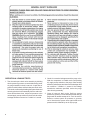
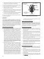
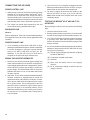
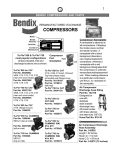
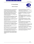
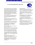
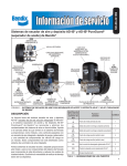
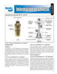
FIGURE 4 - BENDIX® AD-9® AND AD-9® IPC AIR DRYER
TURBO CUT-OFF
The initial purge and desiccant cartridge decompression
lasts only a few seconds and is evidenced by an audible
burst of air at the Bendix® AD-9® or AD-9® IPC air dryer
exhaust.
The actual reactivation of the desiccant drying bed begins
as dry air flows from the purge volume through the desiccant
cartridge purge orifice and into the desiccant drying bed.
Pressurized air from the purge volume expands after
passing through the purge orifice; its pressure is lowered
and its volume increased. The flow of dry air through the
drying bed reactivates the desiccant material by removing
the water vapor adhering to it. Generally 15–30 seconds are
required for the entire purge volume of a standard Bendix
AD-9 or AD-9 IPC air dryer to flow through the desiccant
drying bed.
The end cover single check valve assembly prevents air
pressure in the brake system from returning to the air dryer
during the purge cycle. After the 30 second purge cycle is
complete, the air dryer is ready for the next charge cycle
to begin.
The purge valve will remain open after the purge cycle is
complete, and will not close until air brake system pressure
is reduced and the governor signals the compressor to
charge.
TURBO CUT-OFF FEATURE (Refer to Figure 4)
The primary function of the turbo cut-off valve is to prevent
loss of engine turbocharger air pressure through the
Bendix AD-9 and AD-9 IPC air dryers in systems where the
compressor intake is connected to the engine turbocharger.
The turbo cut-off valve also reduces the “puffing” of air out
4
LOWER
BRACKET
CONTROL
PORT
TURBO
CUT-OFF
PISTON
SUPPLY
PORT
SUPPLY
PORT
TURBO
CUT-OFF
PISTON
BW
CHECK
VALVE
ASSEMBLY
PURGE AD-9
VALVE
CHARGE MODE PURGE
HOUSING
VALVE
ASSEMBLY
DISCHARGE
PORT
FIGURE 5 - BENDIX® AD-9® AND AD-9® IPC AIR DRYER
CROSS SECTION
the open exhaust when a naturally aspirated, single cylinder
compressor equipped with an inlet check valve is in use.
At the onset of the purge cycle, the downward travel of
the purge piston is stopped when the turbo cut-off valve
(tapered portion of purge piston) contacts its mating metal
seat in the purge valve housing. With the turbo cut-off valve
seated (closed position), air in the discharge line and air
dryer inlet port is restricted from entering the air dryer. While
the turbo cut-off effectively prevents loss of turbocharger
boost pressure to the engine, some “seepage” of air may
be detected under certain conditions of compressor engine
and turbocharger operation. Even so, there will always be
low pressure trapped in the discharge line.
PREVENTIVE MAINTENANCE
Important: Review the warranty policy before performing
any intrusive maintenance procedures. An extended
warranty may be voided if intrusive maintenance is
performed during this period. Note: It is acceptable for
the purge valve to be maintained as necessary, (i.e., the
installation of a purge valve maintenance kit), without
voiding the warranty.
Because no two vehicles operate under identical
conditions, maintenance and maintenance intervals will
vary. Experience is a valuable guide in determining the
best maintenance interval for any one particular operation.
Every 900 operating hours or 25,000 miles or every
three (3) months:
1. Check for moisture in the air brake system by opening
reservoirs, drain cocks, or valves and checking for
presence of water. If moisture is present, the desiccant
may require replacement; however, the following
conditions can also cause water accumulation and
should be considered before replacing the desiccant:
A. An outside air source has been used to charge the
system. This air did not pass through the drying bed.
AD-9® / AD-9® IPC
AIR DRYER
LOWER
MOUNTING
BRACKET
END COVER
B. Air usage is exceptionally high and not normal for
a highway vehicle. This may be due to accessory
air demands or some unusual air requirement that
does not allow the compressor to load and unload
(compressing and non-compressing cycle) in
a normal fashion. Check for high air system
leakage. If the vehicle vocation has changed it may
be necessary to upgrade the compressor size.
Refer to Appendix A, Table A and the column titled
Vehicle Vocation.
C. The air dryer has been installed in a system that
has been previously used without an air dryer. This
type of system will be saturated with moisture and
several weeks of operation may be required to dry
it out.
D. Location of the air dryer is too close to the air
compressor. Refer to the Locating Bendix® AD-9®
and AD-9® IPC Air Dryer On Vehicle section and
Appendix A, Table A, column 2 for discharge line
length; or
E. In areas where more than a 30 degree range of
temperature occurs in one day, small amounts
of water can accumulate in the air brake system
due to condensation. Under these conditions, the
presence of small amounts of moisture is normal
and should not be considered as an indication that
the dryer is not performing properly.
Note: A small amount of oil in the system may be normal
and should not, in itself, be considered a reason to
replace the desiccant; oil stained desiccant can function
adequately.
2. Check mounting bolts for tightness. Re-torque to
270–385 inch pounds.
3. Perform the Operation & Leakage Tests listed in this
publication.
Oil removal requirements for air brake quality vary by
vehicle manufacturer. Because vehicle vocation and
maintenance can influence when the AD-9® IPC air dryer
cartridge requires replacement, each fleet should modify
their replacement schedule based on experience. The
change out interval will be extended if the compressor
passes a low level of particles, and the interval will be
reduced if excessive carbon particles are delivered to the
dryer inlet. Higher compressor build up times at idle and
FEMALE
CONNECTOR
MALE
CONNECTOR
LATCH MUST BE
INSERTED UNTIL
IT SNAPS OVER
TAB ON MATING
CONNECTOR
SIDE VIEW
END VIEW
A two lead, 12 inch, wire harness with attached weather
resistant connector is supplied with all retrofit and
replacement Bendix® AD-9® and AD-9® IPC air dryers.
Connect one of the two leads of the wire harness to
the engine kill or ignition switch. The remaining lead of
the wire harness must be connected to a good vehicle
ground. A fuse should be installed in the power carrying
wire; install a 10 amp fuse for 12 volt heaters and a 5
amp fuse for a 24 volt heater. Use 14 AWG wire if it
is necessary to lengthen the wire harness provided.
Make certain all wire splices are waterproofed. Tie
wrap or support all electrical wire leading to the
AD-9® or AD-9® IPC air dryer.
FIGURE 6 - HEATER AND THERMOSTAT CONNECTOR
water or oil in downstream reservoirs indicate an AD-9®
IPC air dryer desiccant cartridge may need to be replaced.
Every 10,800 hours; 300,000 miles or 36 months:
1. Rebuild the air dryer including the desiccant cartridge.
Note: The desiccant change interval may vary from vehicle
to vehicle. Although typical desiccant cartridge life is three
years, many will perform adequately for a longer period of
time. In order to take maximum advantage of desiccant life
and assure that replacement occurs only when necessary, it
is important that Operation & Leakage Tests be performed.
WARNING!
This air dryer is intended to remove moisture and other
contaminants normally found in the air brake system.
Do not inject alcohol, anti-freeze, or other de-icing
substances into or upstream of the air dryer. Alcohol
is removed by the dryer, but reduces the effectiveness
of the device to dry air. Use of other substances can
damage the air dryer and may void the warranty.
5
OPERATION & LEAKAGE TESTS
1. Test the outlet port check valve assembly by building
the air system to governor cut-out and observing a test
air gauge installed in the #1 reservoir. A rapid loss of
pressure could indicate a failed outlet port check valve.
This can be confirmed by bleeding the system down and
removing the check valve assembly from the end cover.
Once this has been done, subject air pressure to the
unit and apply a soap solution to the check valve side.
Leakage should not exceed a 1” bubble in 1 second.
6
2. Check for excessive leakage around the purge valve.
With the compressor in loaded mode (compressing
air), apply a soap solution to the purge valve housing
assembly exhaust port and observe that leakage does
not exceed a 1” bubble in 1 second. If the leakage
exceeds the maximum specified, service the purge
valve housing assembly.
3. Close all reservoir drain cocks. Build up system
pressure to governor cut-out and note that the air dryer
purges with an audible escape of air. “Fan” the service
brakes to reduce system air pressure to governor
cut-in. Note that the system once again builds to full
pressure and is followed by an air dryer purge.
4. Check the operation of the safety valve by pulling
the exposed stem while the compressor is loaded
(compressing air). There must be an exhaust of air while
the stem is held and the valve should re-seat when the
stem is released.
5. Check all lines and fittings leading to and from the air
dryer for leakage and integrity.
6. Check the operation of the end cover heater and
thermostat assembly during cold weather operation as
follows:
A. Electric Power to the Dryer
With the ignition or engine kill switch in the ON
position, check for voltage to the heater and thermostat
assembly using a voltmeter or test light. Unplug the
electrical connector at the air dryer and place the test
leads on each of the pins of the male connector. If there
is no voltage, look for a blown fuse, broken wires, or
corrosion in the vehicle wiring harness. Check to see
if a good ground path exists.
B. Thermostat and Heater Operation
Turn off the ignition switch and cool the end cover
assembly to below 40 degrees Fahrenheit. Using
an ohmmeter, check the resistance between the
electrical pins in the female connector. The resistance
should be 1.5 to 3.0 ohms for the 12 volt heater
assembly and 6.8 to 9.0 ohms for the 24 volt heater
assembly.
Some early models of the Bendix® AD-9® air dryer will
have resistance readings of 1.0 to 2.5 ohms for the 12
volt heater assembly and 4.8 to 7.2 ohms for the 24
volt heater assembly. If the resistance is higher than
the maximum stated, replace the purge valve housing
assembly, which includes the heater and thermostat
assembly.
Warm the end cover assembly to over 90 degrees
Fahrenheit and again check the resistance. The
resistance should exceed 1000 ohms. If the
resistance values obtained are within the stated
limits, the thermostat and heater assembly is
operating properly. If the resistance values obtained
are outside the stated limits, replace the purge valve
housing assembly, which includes the heater and
thermostat assembly.
REBUILDING THE BENDIX ® AD-9 ® AND
AD-9 ® IPC AIR DRYERS
GENERAL
If, after completing the routine operation and leakage tests,
it has been determined that one or more components of the
air dryer requires replacement or maintenance, refer to the
maintenance kit listing in this manual or the Bendix® Quick
Reference Catalog (BW1114) for complete kit information.
When rebuilding or replacing components of the air dryer,
use only genuine Bendix parts. For ease in servicing
the Bendix® AD-9® and AD-9® IPC air dryer desiccant
cartridge assemblies, it is recommended that the air dryer
be removed from the vehicle.
The kit illustrations on the following pages show the
kit contents and will be referenced throughout the
rebuilding procedures.
BENDIX ® AD-9 ® AND AD-9 ® IPC AIR DRYER
REMOVAL
1. Park the vehicle on a level surface and prevent
movement by means other than the brakes.
2. Drain all reservoirs to 0 psi (0 kPa). — Caution:
compressor discharge line may still contain residual
pressure.
3. Identify and disconnect the three air lines from the end
cover and note the position of end cover ports relative
to the vehicle. See Figure 1.
4. Unplug the vehicle wiring harness from the heater and
thermostat assembly connector on the purge valve
housing assembly. See Figure 6.
5. Loosen the 5/16" hex cap screw and sleeve nut
securing the upper mounting strap to the upper
mounting bracket. See Figure 7, illustration A.
Some air dryers may contain a one piece upper
mounting strap as shown in Figure 7, illustration B. If
this is type of strap is present, loosen the adjustment
locknut and remove the strap and isolator from the
upper bracket.
6. Mark and remove the two 3/8" end cover cap screws,
locknuts, and four special washers that secure the
lower mounting bracket to the end cover. Also be sure
to mark these two holes of the end cover. (These bolts
are longer than the other 6 bolts.) Retain the mounting
hardware. See Figure 7, illustrations A and B.
7. Remove the air dryer from the vehicle.
7
MAINTENANCE KITS
Kit Part
Number
Service New (S)
or Reman
Exchange (RX)
Purge
Valve Type
Heater
Connector
Color
107695
S
–
–
–
5002080
S
–
–
–
5009610
S
–
–
–
107799
S
–
–
–
End Cover Check Valve Assembly Replacement 3/4 inch thread size.
End Cover Check Valve Assembly Replacement 1/2 inch thread size.
107800N
S
–
–
–
5005037
S
Hard Seat
–
–
5005893
S
Soft Seat
–
–
Illustration
Complete Mounting Bracket Kit - Contains the
upper and lower brackets as well as the necessary
mounting hardware.
A
Mounting Kit
B
C
Purge Valve Housing Maintenance Kit - Contains
the parts necessary to rebuild the air portion of
the purge valve housing and does not include the
heater and thermostat.
D
K041395
S
–
–
–
Universal Check Valve Kit
E
5003838
S
–
–
–
Exhaust Cover Kit
F
5004224N
S
–
–
–
Silencer Kit
G
107796
S
–
–
–
107794X
RX
–
–
–
Desiccant Cartridge Replacement Kit - Contains
the parts necessary to change the desiccant
cartridge only. Non-IPC Air Dryer
K028830
8
Kit Description
S
–
–
–
Desiccant Cartridge Replacement Kit - Contains
the parts necessary to change the desiccant
cartridge only. IPC Air Dryer
109960
S
–
–
–
5000457
S
–
–
–
109961
S
–
–
–
800405
S
Soft Seat
12V-75W
White
5004338
S
Soft Seat
24V-75W
Gray
5004341X
RX
Soft Seat
12V-75W
White
5004342X
RX
Soft Seat
24V-75W
Gray
5004479
S
Hard Seat
12V-75W
White
Purge Valve Housing Assembly
5004480
S
Hard Seat
24V-75W
Gray
(w/heater and thermostat)
5004381
S
Hard Seat
24V-100W
Yellow
5004339
S
DLU
12V-75W
White
5004340
S
DLU
24V-75W
Gray
5006580
S
DLU
24V-100W
Yellow
See Catalog
BW1114
S and RX
–
–
–
109578
S
–
12V-75W
White
Makeup Line Kit
H
I
Adaptor Kit
J
End Cover Replacement
K
Heater and Thermostat Kit
L
109579
S
–
24V-75W
Gray
5002595
S
–
24V-100W
Yellow
109871N
S
–
–
–
Heater Electrical Splicing Kit
M
113209
S
–
–
–
Universal Mounting Plate
N
SLEEVE
NUT
MOUNTING
STRAP
MOUNTING STRAP
ADJUSTING NUT
ISOLATOR
MOUNTING
SADDLE
5/16" HEX
HEAD SCREW
UPPER BRACKET
LOCKNUT
SPECIAL
WASHER
LOCKNUT
SPECIAL
WASHER
LOWER
MOUNTING
BRACKET
O-RING
LOWER
MOUNTING
BRACKET
SPECIAL
WASHER
CHECK
VALVE
SPECIAL
WASHER
3/8" END
COVER CAP
SCREW
3/8" END COVER
CAP SCREW
A
STANDARD MOUNTING BRACKET KIT
B
MOUNTING BRACKET KIT
SMALL O-RING
DELIVERY CHECK
VALVE PLUG
(NOT INCLUDED
IN KIT)
CHECK VALVE
MAINTENANCE KIT
C
O-RING
MEDIUM O-RING
SPRING
LARGE O-RING
CHECK VALVE
QUAD RING
HORIZONTAL
PISTON
ASSEMBLY
BW
PURGE VALVE
ASSEMBLY
(NOT
INCLUDED
IN KIT)
BW
WASHER
SCREW
RETURN
SPRING
VERTICAL
PURGE
VALVE
EXHAUST
GUIDE
SHOULDER
BOLT
PURGE VALVE HOUSING MAINTENANCE KIT
DELIVERY CHECK
VALVE HOUSING
(NOT INCLUDED
IN KIT)
D
RETAINER
O-RING
CHECK VALVE
SPRING
DELIVERY CHECK VALVE KIT
E
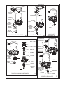
FIGURE 7 - MAINTENANCE KIT CONTENTS (ILLUSTRATIONS A THROUGH E)
9
BW
GASKET
GASKET
EXHAUST COVER
EXHAUST
COVER
SCREWS
ADAPTER
ADAPTER
SCREWS
EXHAUST COVER
KIT F
ADAPTER
SILENCER
BODY
FILTER
SILENCER
SILENCER
COVER
EXHAUST
COVER
EXHAUST
COVER SCREWS
DESICCANT
CARTRIDGE
DESICCANT
CARTRIDGE
O-RING
OUTER
HOUSING
O-RING
G
SILENCER KIT
DESICCANT CARTRIDGE KIT
SMALL
O-RING
H
MEDIUM
O-RING
LARGE
O-RING
STANDARD
PURGE VALVE
ASSEMBLY
CHECK VALVE
WASHER
SCREWS
STANDARD PURGE VALVE
SMALL
O-RING
DISCHARGE
LINE
UNLOADER
PURGE VALVE
ASSEMBLY
ADAPTER
LARGE
O-RING
CHECK
VALVE
MAKEUP AIR LINE
ADAPTER
LETTER "U" STAMPED HERE
TO IDENTIFY DLU ASSEMBLY
DISCHARGE LINE UNLOADER PURGE VALVE
J
FIGURE 8 - MAINTENANCE KIT CONTENTS (ILLUSTRATIONS F THROUGH J)
10
MAKEUP LINE KIT
I
SMALL
O-RING
MEDIUM
O-RING
SCREW
LARGE
O-RING
SEALING
RING
DESICCANT
CARTRIDGE O-RING
HEATER &
THERMOSTAT
OUTER HOUSING
O-RING
HEATER & THERMOSTAT KIT
END COVER
L
WIRE HARNESS
ASSEMBLY
END COVER REPLACEMENT KIT
K
UNINSULATED
BUTT SPLICE
CONNECTOR
EYELET
W/HEAT SHRINK
INSULATOR
ADHESIVE LINED
HEAT SHRINK TUBING
HEATER ELECTRICAL SPLICING KIT
UNIVERSAL
MOUNTING PLATE
M
N
FIGURE 9 - MAINTENANCE KIT CONTENTS (ILLUSTRATIONS K THROUGH M)
DISASSEMBLY
Delivery Check Valve Removal
The following disassembly procedure is presented for
reference purposes and presupposes that a major rebuild
of the Bendix® AD-9® or AD-9® IPC air dryer is being
undertaken. Several replacement parts and maintenance
kits are available which do not require full disassembly. The
instructions provided with these parts and kits should be
followed in lieu of the instructions presented here. Refer
to Figures 7, 8 and 9 during disassembly.
The current style AD-9 ® air dryer end cover has a horizontal
delivery check valve while earlier styles contained a vertical
design. Identify the style of AD-9® air dryer end cover and
proceed to the appropriate step for removal. See Figure
7, illustration E.
Caution: While performing service on the AD-9® and
AD-9® IPC air dryers, it is not recommended that a
clamping device (vise, C-clamp, etc.) be used to hold
any die cast aluminum component, as damage may
result. To hold the end cover, install a pipe nipple in
the supply port and clamp the nipple into a vise.
1. Vertical Delivery Check Valve Removal – Using an
adjustable wrench or a 1-3/4" socket, remove the
delivery check valve assembly and o-ring. Remove
the o-ring from the check valve assembly.
Horizontal Delivery Check Valve Removal – Remove
the delivery check valve plug from the air dryer end
cover.
2. Remove the spring, check valve body, and o-ring.
11
Silencer Removal
If the air dryer purge valve has a silencer attached to it,
identify the style of silencer before attempting to remove
it. There are two different styles of silencers that have
been used with the Bendix® AD-9® air dryer. One design
is secured to the air dryer purge valve adapter with four
cap screws that are visible from the bottom. The other is
a snap-on design. See Figure 8, illustration G.
Screw Mounted Silencer
1. Remove the four screws that secure the exhaust cover,
silencer cover, filter and silencer body to the adapter.
2. Remove the three screws that secure the adapter to
the purge valve. Remove the adapter and gasket.
Snap-on Silencer
1. Firmly grip the silencer and pull it away from the air
dryer end cover.
2. Slide the adapter off of the exhaust cover.
3. Remove the three screws that secure the exhaust cover
to the purge valve housing assembly of the end cover.
Remove the exhaust cover and gasket.
Purge Valve Removal
1. Remove the three 1/4" screws that secure the purge
valve housing assembly to the end cover assembly. Pull
the purge valve housing assembly out of the end cover
assembly. Remove the three o-rings from the exterior
of the purge valve housing assembly. (The medium
o-ring is not included in DLU models.) The o-rings may
be lodged in the end cover bores, if so, they must be
removed. Refer to Figure 8, illustration J.
2. Purge Valve Disassembly:
Note: In some cases a flat (non-extended) exhaust
cover is used. If an extended type exhaust cover is in
use, (to accommodate the attachment of an exhaust
hose), the exhaust cover must be carefully peeled off of
the purge valve housing. Use a thin flat blade to pry
the exhaust cover off, taking care not to damage
the potting material (RTV sealant) under the cover.
Removal of the piston from the purge valve housing
assembly requires a tool to hold the head of the purge
piston while unscrewing the purge valve shoulder
bolt. Remove the piston from the purge valve housing
assembly using a twelve point 1/4" socket to hold the
head of the purge valve shoulder bolt. See Figure 7,
illustration D.
A. Secure the top of the purge piston assembly using
the two opposing cast indentations and a removal
tool. Remove the purge valve shoulder bolt from
the bottom of the purge valve housing assembly.
Remove the exhaust guide and purge valve from
the purge valve housing.
B. Remove the purge piston assembly and return
spring from the opposite end of the purge valve
housing assembly. Remove the quad ring from the
purge piston assembly.
SMALL
O-RING
MEDIUM
O-RING
HEATER &
THERMOSTAT
SCREW
LARGE
O-RING
Step A
SEALING
RING
PURGE VALVE
ASSEMBLY
HEATER
ELEMENT
HEATER &
THERMOSTAT
HEATER &
THERMOSTAT
PURGE
VALVE
ASSEMBLY
Step B
SEALING RING
RUBBER CUSHION
THERMOSTAT
SEALING RING
SEALING RING
HEATER
ELEMENT
RUBBER CUSHION
THERMOSTAT
PURGE VALVE HOUSING W/HEATER & THERMOSTAT
(SECTIONAL VIEW FROM BOTTOM)
PURGE VALVE
W/HEATER & THERMOSTAT INSTALLED
(SECTIONAL VIEW FROM BOTTOM)
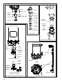
FIGURE 10 - HEATER & THERMOSTAT REMOVAL & INSTALLATION
12
SPECIAL ASSEMBLY,
MUST BE REPLACED BY
AD-9 SOFT SEAT
AIR DRYER ASSY.
SPECIAL ASSEMBLY,
MUST BE REPLACED BY
AD-9 SOFT SEAT
AIR DRYER ASSY.
MAKEUP AIR LINE
DELIVERY PORT
ADAPTER
(WITH 90° FITTING)
DELIVERY PORT
ADAPTER
(WITH 90° FITTING)
CHECK VALVE
(WITH 90° FITTING)
MAKEUP AIR LINE
FIGURE 11 - BENDIX® AD-9® DROP IN AIR DRYER
Heater and Thermostat Assembly Removal
1. Remove the two screws that secure the heater and
thermostat assembly to the purge valve assembly. See
Figure 9, illustration L for kit contents.
CAUTION
DO NOT PULL THE HEATER & THERMOSTAT
ASSEMBLY STRAIGHT OUT OF THE PURGE VALVE
BODY! READ STEP 2 COMPLETELY BEFORE
ATTEMPTING REMOVAL.
2. Study Figure 10 closely and note the "Y" shape of the
Heater & Thermostat assembly in its installed position
in the purge valve housing. As illustrated, remove the
heater & thermostat assembly by gently "rotating" the
connector to the left (Step A) until the thermostat clears
the purge valve housing, then slide the heater element
out, to the right and up (Step B).
End Cover Removal
1. Remove the remaining six 3/8" cap screws, locknuts
and twelve special washers that secure the end cover to
the housing air dryer housing. Separate the end cover
and desiccant cartridge from the housing. See Figure
9, illustration K.
2. Remove the end cover to outer housing o-ring.
3. Do not remove the safety valve from the end cover
unless it has been proven defective. If replacement
is required, apply thread sealant or Teflon ® tape on
the threads of the replacement valve and torque
to 120–400 in. lbs. See Figure 1 for safety valve
location.
4. Place a strap or chain wrench around the desiccant
cartridge so that it is approximately 2–3 inches
away from the end cover. Rotate the cartridge
counterclockwise until it completely separates from the
end cover.
Note: A substantial torque (up to 50 lb. ft.) may be
required to perform this disassembly.
5. Remove the desiccant cartridge o-ring from the end
cover.
Drop In Air Dryer Makeup Line Removal
1. Before beginning, note the approximate angle of
the fittings, check valve and the general routing of
the makeup line on the air dryer. It is important that
the same approximate routing be duplicated during
re-installation. See Figure 11.
2. Disconnect the makeup line from the 90 degree fitting
on the check valve.
3. Disconnect the makeup line from the 90 degree fitting
on the port adapter itself or the check valve. Remove
the adapter along with the attached 90 degree fitting.
CLEANING & INSPECTION
1. Using mineral spirits or an equivalent solvent, clean
and thoroughly dry all metal parts.
2. Inspect the interior and exterior of all metal parts
that will be reused for severe corrosion, pitting and
cracks. Superficial corrosion and/or pitting on the
exterior portion of the upper and lower body halves is
acceptable.
3. Inspect the bores of both the end cover and the purge
valve housing for deep scuffing or gouges.
13
4. Make certain that all purge valve housing and end cover
passages are open and free of obstructions.
5. Inspect the pipe threads in the end cover. Make certain
they are clean and free of thread sealant.
APPLY LUBRICANT
DELIVERY CHECK
VALVE BODY
CHECK
VALVE
SPRING
6. Inspect the purge valve housing bore and seats for
excessive wear and scuffing.
7. Inspect the purge valve piston seat for excessive wear.
8. Inspect all air line fittings for corrosion. Clean all old
thread sealant from the pipe threads.
9. All o-rings removed should be discarded and replaced
with new o-rings provided in appropriate kit(s).
Any component exhibiting a condition described in step 1
to 8 should be replaced.
SPRING
RETAINER
7/16" DEEP
SOCKET WITH A
3/8" DRIVE
BENCH VISE
FIGURE 12 - VERTICAL DELIVERY CHECK VALVE
ASSEMBLY
The following assembly procedure is presented for
reference purposes and presupposes that a major rebuild
of the Bendix® AD-9® or AD-9® IPC air dryer is being
undertaken. Several replacement parts and maintenance
kits are available which do not require full disassembly. The
instructions provided with these parts and kits should be
followed in lieu of the instructions presented here. Refer
to Figures 7, 8 and 9 during assembly.
self-tapping screws. Start all three screws by hand
then torque to 50–80 in. lbs.
Delivery Check Valve Assembly
The current style AD-9 ® air dryer end cover has a
horizontal delivery check valve while earlier styles
contained a vertical design. Identify the style of AD-9 ®
air dryer end cover and proceed to the appropriate step
for installation. See Figure 7, illustration E.
Purge Valve Housing Assembly
Vertical Delivery Check Valve –
1. Prior to assembly, coat all o-rings, o-ring grooves, and
bores with a generous amount of the lubricant included
in the maintenance kit. See Figure 7, illustration D.
1. Assemble the spring to the retainer and check valve.
Ensure the spring is fully seated on the retainer and
the check valve.
2. Lubricate the entire spherical surface of the check valve
and bore chamfer of the check valve housing with the
lubricant provided in the kit.
A. Install the quad-ring in its groove on the O.D. of the
purge piston. Place the return spring in the bore of
the purge valve housing. Insert the purge piston into
the I.D. of the return spring. Place the purge valve
guide onto the shoulder bolt followed by the purge
valve. Using a ratchet or wrench, screw the purge
valve, purge valve guide and shoulder bolt into the
purge housing until it bottoms. This will require a tool
to hold the top of the purge piston from rotating as the
shoulder bolt is screwed into the bottom of the purge
piston to complete the purge valve assembly. Torque
the shoulder bolt to 60–90 in. lbs.
B. Install the o-rings on the purge valve housing, placing
each in its appropriate location. Note the medium
o-ring is not used on Discharge Line Unloaded
(DLU) models. If the exhaust cover was removed
during disassembly, install it on the purge valve
assembly making certain the “bubble” portion is
positioned over the thermostat. Install the assembled
purge valve housing in the end cover. Make certain
to orient both parts such that the connector is
approximately 10 degrees clockwise from the supply
port, while making certain the purge valve housing is
fully seated against the end cover. Secure the purge
valve housing to the end cover using the three 1/4"
14
3. Place the retainer, spring and check valve subassembly into the check valve housing. Press the
retainer using a 7/16" deep socket with a 3/8" drive,
and a vise as shown in Figure 12.
4. Inspect the bore of the end cover. Make certain that the
end cover passage is open and free of obstructions.
5. Install the o-ring on the outer body of the delivery check
valve assembly. Ensure the o-ring is seated properly
and not twisted. Lubricate the o-ring.
6. Install the delivery check valve assembly into the end
cover. Torque to 200–250 in. lbs.
Horizontal Delivery Check Valve –
1. Lubricate the o-ring and the long check valve body with
the lubricant provided. Use only the lubricant contained
in the kit.
2. Install the o-ring on the long check valve body. Push
the o-ring down, over the 3 guide lands until it is in the
o-ring groove. Ensure the o-ring is seated properly
and not twisted.
3. Install the spring on the white check valve body so that
the small coils of the spring slip over the check valve
body.
2
6
4
5
3
1&9
8
7
FIGURE 13 - END COVER TO HOUSING TORQUE PATTERN
4. Install the assembled long check valve body, o-ring,
and spring in the end cover delivery check valve port
so that the o-ring rests on its seat in the end cover and
the spring is visible.
5. Install the delivery check valve plug that was removed
during the disassembly, into the air dryer end cover.
See Figure 5. Torque the plug to 130–170 inch pounds.
Drop In Air Dryer Makeup Line Assembly
1. Install the adapter and the attached 90 degree fitting in
the air dryer. Take care that the replacement adapter
and attached fitting is in the same approximate position
as the original. See Figure 11.
Air Dryer Assembly
1. Install the desiccant cartridge o-ring in its groove in
the end cover. Using a light coat of lubricant (included
in kit), lubricate the bottom of the desiccant cartridge
in the area that will contact the o-ring and end cover.
Screw the desiccant cartridge into the end cover until
contact is made between it and the o-ring. Using a strap
or chain wrench positioned 2–3 inches from the bottom
of the cartridge, turn the desiccant cartridge clockwise
180–225 degrees beyond the position where initial
contact was made between the cartridge and end cover
o-ring. Torque should not exceed 50 ft. lbs.
2. Install the end cover outer housing o-ring on the
shoulder in the end cover. Place the housing over the
desiccant cartridge and align the holes. Install the six
3/8" cap screws, locknuts and twelve special washers,
making certain they are in the proper position as marked
during disassembly. The two longer 3/8" cap screws will
be used to secure the air dryer to its mounting bracket.
Tighten the six cap screws and nuts in a star pattern
in a fashion similar to Figure 13; depending on lower
bracket location. Torque to 270–385 in. lbs.
Note: The two remaining bolt holes in the end cover and
two 3/8" cap screws must be the ones marked during
disassembly to assure proper orientation of the ports
and adequate length of the cap screws.
INSTALLATION
1. Install the assembled Bendix® AD-9® or AD-9® IPC air
dryer back onto the vehicle by slipping it into the upper
mounting bracket. Align the two unused holes in the end
cover with the bottom mounting bracket such that the
bottom bracket supports the air dryer. The air dryer end
cover should rest on the bracket. Using the remaining
two 3/8" cap screws, four special washers, and two
locknuts, secure the air dryer to the lower bracket.
Tighten, then torque the two remaining cap screws to
270–385 in. lbs. See Figure 14.
LOWER
BRACKET
2-1/8"
END
COVER
2. Install the check valve and fitting, taking care that the
replacement is in the same approximate position as the
original.
3. Install the makeup line and tighten the tubing nuts at
both ends while preventing the 90 degree fittings from
turning. Tighten the nuts sufficiently to prevent air
leakage, but do not over tighten.
EXTRA
LONG
BRACKET
CAP SCREW
FIGURE 14 - LOWER BRACKET INSTALLATION
2. See Figure 7, illustrations A and B, to determine the
mounting bracket type.
SPECIAL
WASHER
Illustration A Style - Attach the mounting strap to the
air dryer and secure it to the mounting saddle with
the 5 /16" X 4-1/2" hex cap screw and nut. Torque to
80–120 in. lbs.
Illustration B Style - Place the isolator between the
upper bracket and air dryer. Secure the air dryer to
the upper bracket with the mounting strap. Tighten the
adjusting nut to 50–60 in. lbs.
15
3. Reconnect the three air lines to the proper ports on the
end cover (identified during disassembly).
4. Reconnect the vehicle wiring harness to the air dryer
heater and thermostat assembly connector by plugging
it into the air dryer connector until its lock tab snaps in
place.
5. Before placing vehicle back into service, perform the
Operation and Leakage Tests stated earlier in this
manual.
RETROFITTING THE BENDIX® AD-9® AIR
DRYER
GENERAL
The following retrofit instructions are presented for
reference purposes only since Bendix aftermarket retrofit
and replacement air dryers are packaged with the most upto-date installation instructions. The instructions packaged
with the Bendix® AD-9® and AD-9® IPC air dryers should be
followed in lieu of those presented here.
The preceding portion of this manual deals with “in-service”
repair and/or replacement of the AD-9® and AD-9® IPC air
dryers. The portion of the manual that follows is concerned
with installing an AD-9® or AD-9® IPC air dryer on a vehicle
not previously equipped with one.
VEHICLE APPLICATION REQUIREMENTS
The basic application requirements presented here apply
to a standard air dryer installation. The majority of highway
vehicles in use today will meet these basic requirements
however, some may not. Examples of vehicles that may
not meet the requirements include, bulk trailer unloading
operations and other high air consumption/continuous flow
systems. While the AD-9® or AD-9® IPC air dryer can be
used on these vehicles, the standard installation procedure
presented in this manual may require modification to
assure proper operation and service life. Consult your local
authorized Bendix parts outlet or sales representative for
additional information.
1. Charge Cycle Time - The Bendix® AD-9® and AD-9® IPC
air dryers are designed to provide clean, dry air for
the brake system. When a vehicle’s air system is used
to operate non-brake air accessories, it is necessary
to determine that during normal, daily operation the
compressor should recover from governor “cut-in” to
governor “cut-out” (usually 100 psi to 120 psi) in 90
seconds or less at engine RPMs commensurate with
the vehicle vocation. If the recovery time consistently
exceeds this limit, it may be necessary to “bypass”
the air accessory responsible for the high air usage.
Consult your local authorized Bendix parts outlet or
sales representative for additional information.
CONTROL
(HIDDEN)
GOVERNOR
SUPPLY
UNLOADER
PORT
DELIVERY
COMPRESSOR
SAFETY VALVE
CON
10 AMP - 12V
5 AMP - 24V
SUP
FUSE
14 GA WIRE
TO IGNITION
& GROUND
FIGURE 11 - AD-9® AIR DRYER CHARGE CYCLE
16
DEL
RESERVOIR
#1
TO RESERVOIR
#2
2. Purge Cycle Time - During normal vehicle operation,
the air compressor must remain unloaded for a
minimum of 20 seconds for the standard air dryer
or 30 seconds for the extended purge model. These
minimum purge times are required to ensure complete
regeneration of the desiccant material. If the purge
time is occasionally shorter than the times specified,
no permanent ill effect should be expected; however, if
the purge time is consistently less than the minimum,
an accessory by-pass system must be installed.
3. Do not locate the AD-9 or AD-9 IPC air dryer near heat
producing components, such as the vehicle exhaust,
and make certain adequate clearance from moving
components (e.g. drive shaft, suspension, pitman arm,
etc.) is provided.
3. European Air Brake Systems - Brake systems that
incorporate compressors without integral unloading
mechanisms, and/or utilize a compressor discharge
line unloader valve, have special Bendix® AD-9® and
AD-9® IPC air dryer installation requirements. Consult
your local authorized Bendix parts outlet or sales
representative for additional information.
5. When choosing the mounting location for the AD-9
or AD-9 IPC air dryer, note the discharge line length
requirements stated under the heading Connecting the
Air Lines, elsewhere in this instruction sheet.
4. Holset “E or QE” Type Air Compressors - In order for the
AD-9 or AD-9 IPC air dryer to function properly when
installed with the Holset Type “E or QE” compressor,
several specialized Holset components are required.
Consult your local authorized Holset parts outlet or
sales representative for additional information.
5. Use of Standard or Extended Purge AD-9 or AD-9 IPC
Air Dryer - Use the following guidelines:
Bendix® AD-9® or
AD-9® IPC Air Dryer
Requirement
Total Vehicle
Reservoir Volume
Less than 9,000 cu. in.
Standard Air Dryer
9,000 - 12,500 cu. in.
Extended Purge Air Dryer
Greater than 12,500 cu. in.
Contact Bendix Rep. or Bendix
Engineering
VEHICLE PREPARATION
1. Park the vehicle on a level surface and prevent
movement by means other than the brakes.
2. Drain all reservoirs to 0 psi (0 kPa).
LOCATING THE BENDIX® AD-9® AIR DRYER ON
VEHICLE
1. The AD-9 or AD-9 IPC air dryer must be mounted
vertically (purge exhaust toward road surface) outside
the engine compartment in an area of air flow while the
vehicle is in motion. The air dryer must not be exposed
to direct wheel splash (located behind axle mud flap is
acceptable).
2. Locate the AD-9 or AD-9 IPC air dryer as close to the
first (supply) reservoir as possible.
4. Locate the AD-9 or AD-9 IPC air dryer on the vehicle
so that a minimum of 11 inches (28 cm) clearance
below the end cover is available to allow servicing.
Alternatively, provide access to the bracket bolts so
the unit may be removed for servicing.
Important Note: Under normal operating conditions,
the maximum inlet air temperature for the AD-9 and
AD-9 IPC air dryers is 160 degrees Fahrenheit.
MOUNTING THE BENDIX® AD-9® AND AD-9® IPC
AIR DRYER
1. To install the lower mounting bracket on the AD-9 or
AD-9 IPC air dryer, it will be necessary to remove and
discard two of the end cover bolts and locknuts. To
determine which end cover bolts to utilize to attach
the lower bracket, take into consideration the piping
connections required to install the air dryer and
use those that will best position the unit for ease of
installation. Locate the bracket such that it cradles
the end cover as shown in Figure 9. Utilizing the two
2-3/8" long cap screws, locknuts and special washers
provided with the AD-9 or AD-9 IPC air dryer retrofit
unit, attach the lower mounting bracket and torque to
270–385 in. lbs.
2. Assemble the mounting strap and upper mounting
bracket as illustrated in Figure 10, by utilizing the 5/16"
cap screw and sleeve nut.
3. Place the upper bracket assembly onto the shell of
the AD-9 or AD-9 IPC air dryer and orient it so that it
bears entirely on the cylindrical surface and does not
extend onto the domed top. The slot spacing between
the upper and lower bracket should be a minimum of
5.5 inches apart. Do not tighten strap onto the shell at
this time.
4. Mount the air dryer on the vehicle using 3/8" bolts
(grade 5 min.) and washers. Torque to 25 ft. lbs. (300
inch pounds.) After positioning and mounting the
upper bracket assembly according to the installation
requirements, torque the 5/16" nut to 80–120 in. lbs.
to tighten strap onto the shell.
17
CONNECTING THE AIR LINES
PURGE CONTROL LINE
1. Install a purge control air line having a minimum inside
diameter of 3/16 inches between the Bendix® AD-9®
or AD-9® IPC air dryer end cover control port and an
unused unloader port on the governor. The control line
must be plumbed direct to the governor and not in series
with automatic drain valves, lubrication systems, etc.
2. The control line should slope downward to the end
cover without forming potential water traps.
DISCHARGE LINE
General:
Refer to Appendix A, Table A for recommended discharge
line lengths and sizes for various vehicle applications and
vocations.
PURGE EXHAUST LINE
1. If it is necessary to direct AD-9 or AD-9 IPC air dryer
discharge contaminants away from vehicle components
it may be necessary to purchase a special exhaust
cover for the AD-9 or AD-9 IPC air dryer (Pc. No.
5003838). A one inch (25.4 mm) I.D. hose can be
clamped on the special air dryer exhaust cover.
WIRING THE HEATER/THERMOSTAT
1. Determine the vehicle’s electrical system voltage and
make certain that the AD-9 or AD-9 IPC air dryer that is
to be installed contains the same voltage heater. Use the
AD-9 or AD-9 IPC air dryer part number to confirm the
proper voltage. The AD-9 and AD-9 IPC air dryers are
available with either a 12 or 24 volt heater which uses
75 watts of power.
2. A two lead, 12 inch, wire harness with attached weather
resistant connector is supplied with all retrofit and
replacement AD-9 and or AD-9 IPC air dryers. Connect
one of the two leads of the wire harness to the engine
kill or ignition switch. The remaining lead of the wire
harness must be connected to a good vehicle ground
(not to the air dryer or its mounting bracket). A fuse
should be installed in the power carrying wire; install a
10 amp fuse for 12 volt heaters and a 5 amp fuse for
a 24 volt heater.
18
3. Use 14 GA wire if it is necessary to lengthen the wire
harness provided with the AD-9 or AD-9 IPC air dryer.
Make certain all wire splices are waterproofed.
4. Tie wrap or support all electrical wire leading to the
AD-9 or AD-9 IPC air dryer at 6–8 inch intervals.
Note: Wires should have sufficient slack and not be
completely taught.
TESTING THE BENDIX® AD-9® AND AD-9® IPC
AIR DRYER
Before placing the vehicle in service, perform the following
tests:
1. Close all reservoir drain cocks.
2. Build up system pressure to governor cut-out and note
that the air dryer purges with an audible escape of air.
3. “Fan” the service brakes to reduce system air pressure
to governor cut-in. Note that the system once again
builds to full pressure and is followed by a purge at the
air dryer exhaust.
4. It is recommended that the following items be tested for
leakage to assure that the AD-9 or AD-9 IPC air dryer
will not cycle excessively.
(A) Total air system leakage (See Bendix® Air Brake
Handbook, BW5057).
(B) Compressor unloader mechanism.
(C) Governor.
(D) Drain cock and safety valve in first (supply)
reservoir.
(E) All air connections leading to and from the first
(supply) reservoir.
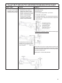
Bendix® AD-9® AND AD-9® IPC AIR DRYER TROUBLESHOOTING CHART
SYMPTOMS
CAUSE
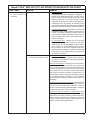
1. Dryer is constantly “cycling” A. Excessive system leakage.
or purging. Dryer purges
IMPORTANT: Note whether air
frequently (every 4 minutes
pressure loss is shown on dash
or less while vehicle is idling).
gauge(s). Pressure loss shown on
gauges is caused by service brake
system or component leakage.
Pressure loss NOT SHOWN
on gauges is caused by supply
system or component leakage.
REMEDY
A. If leakage IS SHOWN on gauges, test for excessive service
brake system leakage.
Allowable leakage:
Pre-121 vehicles, single vehicles - 2 psi / minute.
Tractor trailer - 3 psi / minute.
121 vehicles, single vehicle - 1 psi / minute per service reservoir.
Tractor trailer - 3 psi / minute per service reservoir. Repair and
retest as required.
If leakage is NOT SHOWN on gauges test for excessive supply
system leakage.
Remove drain cock or valve in supply reservoir (wet tank) and
install air gauge. Build system pressure, allow air dryer to purge
and observe air gauge in supply reservoir. Pressure drop should
not exceed 1 psi per minute.
Perform tests 1 to 6 in the order presented.
19
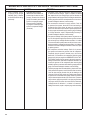
Bendix® AD-9® AND AD-9® IPC AIR DRYER TROUBLESHOOTING CHART
SYMPTOMS
CAUSE
1. Dryer is constantly “cycling” A. Excessive system leakage.
or purging. Dryer purges
IMPORTANT: Note whether air
frequently (every 4 minutes
pressure loss is shown on dash
or less while vehicle is idling)
gauge(s). Pressure loss shown on
(continued).
gauges is caused by service brake
system or component leakage.
Pressure loss NOT SHOWN
on gauges is caused by supply
system or component leakage.
(continued)
REMEDY
1. Test fittings, hoses, lines and connections. Apply soap solution
to detect excessive leakage. Tighten or replace as needed
then repeat the air dryer charge-purge cycle and observe the
gauge installed in the supply reservoir. If leakage is within limits,
remove gauge from reservoir and replace drain cock or valve. If
excessive leakage is detected, continue testing.
2. Test accessories connected to supply reservoir. Drain all
air pressure from system, disconnect all air lines leading to
accessories (fan clutch, wipers, air seats, etc.) and plug the
reservoir at disconnection point. Build air system pressure until
air dryer purges and observe supply reservoir gauge. If leakage
is no longer excessive, repair or replace leaking accessory. If
excessive leakage is detected, continue testing.
3. Test governor leakage. Build system pressure to governor cutout, turn off engine and apply soap solution to governor exhaust
port and around cap. Leakage should not exceed a 1 in. bubble
in 5 seconds. Reduce system pressure to 80 psi or less, and reapply soap solution. Leakage should not exceed a 1 in. bubble in
5 seconds. If excessive leakage is detected in either test, repair
or replace governor.
4. Test compressor unloader leakage. Drain all air pressure
from system and remove the governor from the compressor.
Temporarily plug the governor unloader port or air line that
mated with, or connected to, the compressor. Build air system
pressure until air dryer purges then IMMEDIATELY SHUT OFF
THE ENGINE. Observe the air gauge in the supply reservoir. If
leakage is within limits, replace the compressor unloaders. Reconnect the governor to the compressor (after removing plug
installed in governor) and retest while observing supply reservoir
gauge. If excessive leakage is detected, continue testing.
5. Test air dryer purge valve and outlet (delivery) check valve. Drain
all air pressure from system, remove the control line connection
at the air dryer and plug the end of the air line leading to the
governor (not the air dryer control port). Build system pressure
to governor cut-out and observe air gauge. If little or no pressure
drop is observed replace the air dryer check valve. If pressure
drop continues, apply soap solution to air dryer purge exhaust
and purge control port (where the control line was removed).
Leakage should not exceed a 1 in. bubble in 5 seconds. If
leakage is excessive, repair or replace purge valve assembly.
20
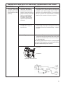
Bendix® AD-9® AND AD-9® IPC AIR DRYER TROUBLESHOOTING CHART
SYMPTOMS
CAUSE
REMEDY
1. Dryer is constantly “cycling” A. Excessive system leakage.
or purging. Dryer purges
IMPORTANT: Note whether air
frequently (every 4 minutes
pressure loss is shown on dash
or less while vehicle is idling)
gauge(s). Pressure loss shown on
(continued).
gauges is caused by service brake
system or component leakage.
Pressure loss NOT SHOWN
on gauges is caused by supply
system or component leakage.
(continued)
6. With gauge installed at RES port of governor, pressure should
not drop below ”Cut-In” pressure at the onset of the compressor
“Unloaded” cycle. If pressure drops, check for “kinks” or
restrictions in line connected to RES port. Line connected to
RES port on governor must be same diameter, or preferably
larger than, lines connected to UNL port(s) on governor.
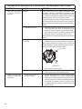
B. Leaking purge valve housing
assembly and/or o-rings in air
dryer end cover.
B. With the supply port open to atmosphere, apply 120 psi at the
control port. Apply a soap solution to the supply port and exhaust
port (purge valve seat area). Permissible leakage - 1" bubble in
5 seconds.
C. Holset® “E” type compressor.
C. Test the Holset® E Compressor unloader system with feedback
line and check valve for proper operation. Make certain Holset
ECON is not in use with the drop-in version of the air dryer, if
so, remove and retest.
When installing a Bendix Drop-In air dryer in a system equipped
with a Holset E or QE compressor, remove the Holset ECON valve
along with its feedback and governor control line.
Check Valve
Feedback Line
Typical Drop-In Air Dryer End Cover
21
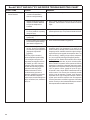
Bendix® AD-9® AND AD-9® IPC AIR DRYER TROUBLESHOOTING CHART
SYMPTOMS
CAUSE
2. Water and/or Oil in Supply or A. Desiccant requires replacement
Service Reservoir.
- excessive contaminants in
desiccant cartridge assembly.
REMEDY
A. Replace desiccant cartridge.
B. Improper discharge line length or
improper line material. Maximum
air dryer inlet temperature is
exceeded.
B. Refer to section entitled Connecting the Air Lines as well as
Appendix A, Table A columns 1 & 2 then check line size and
length.
C. Air system charged from outside
air source (outside air not passing
through air dryer)
C. If system must have outside air fill provision, outside air should
pass through the air dryer. This practice should be minimized.
D. Air dryer not purging (see
Symptom #5).
D. See Symptom #5.
E. Purge (air exhaust) time insufficient E. Check causes and remedies for Symptom #1.
due to excessive system leakage
(see causes for Symptom #1).
F. Excessive air usage, duty cycle
F. See Appendix A, Table A, column 1, for recommended
too high - Air dryer not compatible
compressor sizes. If the compressor is “too small” for the
with vehicle air system requirement
vehicle vocation (for example, where a vehicle’s vocation has
(Improper air dryer/vehicle
changed or service conditions exceed the original vehicle or
application).
engine OE spec’s) then upgrade the compressor. Note: The
costs incurred (e.g. installing a larger capacity compressor,
NOTE: Duty Cycle is the ratio of
etc.) are not covered under original compressor warranty.
time the compressor spends building
air to total engine running time. Air
compressors are designed to build air
(run “loaded”) up to 25% of the time.
Higher duty cycles cause conditions
that affect air brake charging system
performance which may require
additional maintenance. Factors
that add to the duty cycle are: air
suspension, additional air accessories,
use of an undersized compressor,
frequent stops, excessive leakage from
fittings, connections, lines, chambers or
valves, etc.
22
Charge Cycle Time - Bendix® AD-9® and AD-9® IPC air dryers
are designed to provide clean, dry air for the brake system.
When a vehicle’s air system is used to operate non-brake air
accessories it is necessary to determine that; during normal,
daily operation the compressor should recover from governor
“cut-in” to governor “cut-out” (usually 100 psi to 120 psi) in
90 seconds or less at engine RPM’s commensurate with the
vehicle vocation. If the recovery time consistently exceeds
this limit, it may be necessary to “bypass” the air accessory
responsible for the high air usage. An example of where a
by-pass system would be required is when the compressor
is used to pressurize a tank trailer for purposes of off-loading
product. Consult your local authorized Bendix parts outlet or
sales representative for additional information.
Bendix® AD-9® AND AD-9® IPC AIR DRYER TROUBLESHOOTING CHART
SYMPTOMS
CAUSE
2. Water and/or Oil in Supply (Continued)
or Service Reservoir
(continued).
REMEDY
Purge Cycle Time - During normal vehicle operation, the
air compressor must remain unloaded for a minimum of 20
seconds for the standard Bendix® AD-9® and AD-9® IPC air
dryer or 30 seconds for the extended purge model. These
minimum purge times are required to ensure complete
regeneration of the desiccant material. If the purge time is
consistently less than the minimum, an accessory by-pass
system must be installed. Consult your local authorized Bendix
parts outlet or sales representative for additional information.
European Air Brake Systems - Brake systems that incorporate
compressors without integral unloading mechanisms and/
or utilize a compressor discharge line unloader valve have
special air dryer installation requirements. Consult your local
authorized Bendix parts outlet or sales representative for
additional information.
Air Compressor Size - Although the AD-9 and AD-9
IPC air dryers can be used in conjunction with larger
compressors, it was designed primarily for units rated for
up to 17 CFM. It is recommended that when using the
AD-9 or AD-9 IPC air dryer with a compressor which has a
rated displacement exceeding 17 CFM that an authorized
Bendix parts outlet or Bendix marketing representative
be contacted for assistance.
G. Restricted discharge line. See Appendix A, Table A, column 1
G. Air compressor discharge and/or
air dryer inlet temperature too high.
& 2 for recommended sizes. If discharge line is restricted or
more than 1/16” carbon build up is found, replace the discharge
line. Replace as necessary.
Discharge Line Freeze-Up. The discharge line must maintain a
constant slope down from the compressor to the air dryer inlet
fitting to avoid low points where ice may form and block the flow.
If, instead, ice blockages occur at the air dryer inlet, insulation
may be added here, or if the inlet fitting is a typical 90 degree
fitting, it may be changed to a straight or 45 degree fitting. For
more information on how to help prevent discharge line freezeups, see Bendix Bulletins TCH-008-021 and TCH-008-022.
Shorter discharge line lengths or insulation may be required in
cold climates.
Insufficient coolant flow through compressor. Inspect coolant line.
Replace as necessary (I.D. is 1/2” min.). Inspect the coolant lines
for kinks and restrictions and fittings for restrictions. Replace as
necessary. Verify coolant lines go from engine block to compressor
and back to the water pump. Repair as necessary.
Restricted air inlet (not enough air to compressor). Check
compressor air inlet line for restrictions, brittleness, soft or sagging
hose conditions, etc. Repair as necessary. Inlet line size is 3/4 ID.
Maximum restriction requirement for compressors is 25 inches
of water. Check the engine air filter and service if necessary (if
possible, check the air filter usage indicator).
23
Bendix® AD-9® AND AD-9® IPC AIR DRYER TROUBLESHOOTING CHART
SYMPTOMS
CAUSE
2. Water and/or Oil in Supply (Continued)
or Service Reservoir
(continued).
REMEDY
Poorly filtered inlet air (poor air quality to compressor). Check
for leaking, damaged or malfunctioning compressor air inlet
components (e.g. induction line, fittings, gaskets, filter bodies,
etc.). Repair inlet components as needed. Note: Dirt ingestion will
damage compressor and is not covered under warranty.
If you found excessive oil present in the service reservoir and you
did not find any issues above, the compressor may be passing oil.
Replace compressor. If still under warranty, follow normal warranty
process.
H. Compressor malfunction.
H. If excessive oil is present in the service reservoir and no other
issues (from above) were found, the compressor may be
passing oil. Test the compressor using the Bendix® BASIC™
cup method as described in the Bendix compressor service
manual and referred to in Appendix A, Table A, column 5.
Replace compressor. If still under warranty, follow normal warranty
process.
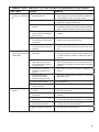
I.
Air by-passes desiccant cartridge I.
assembly.
If the vehicle uses a Holset ® compressor, inspect the
feedback check valve for proper installation and operation.
When replacing the desiccant cartridge, make sure desiccant
cartridge assembly is properly installed and sealing rings are in
place on mounting surface of desiccant cartridge.
Check Valve
Feed Back Line
Typical Drop-In Air Dryer End Cover
J. Desiccant requires replacement.
3. Oil present at air dryer purge A. Air brake charging system is
exhaust or cartridge during
functioning normally.
maintenance.
24
J. Replace desiccant cartridge assembly. Refer to Appendix A,
Table A columns 3 & 4 for recommended intervals.
A. Air dryers remove water and oil from the air brake charging
system. A small amount of oil is normal. Check that regular
maintenance is being performed and that the amount of oil in
the air tanks (reservoirs) is within the acceptable range shown
on the BASIC cup (see also column 5 of Appendix A, Table
A). Replace the air dryer cartridge as needed and return the
vehicle to service.
Bendix® AD-9® AND AD-9® IPC AIR DRYER TROUBLESHOOTING CHART
SYMPTOMS
CAUSE
REMEDY
4. Safety valve on air dryer A. Restriction between air dryer and
“popping off” or exhausting
supply (first) reservoir.
air.
A. Check to determine if air is reaching supply reservoir. Inspect
for kinked tubing or hose. Check for undrilled or restricted hose
or tubing fittings and repair or replace as needed.
B. Air dryer safety valve malfunction.
B. Verify relief pressure is at vehicle or component manufacturer
specifications. Replace if malfunctioning.
C. Desiccant cartridge maintenance
required.
C. Refer to Appendix A ,Table A and column 3. Check compressor
for excessive oil passing and/or correct compressor installation.
Repair or replace as necessary. Replace desiccant cartridge.
D. Malfunctioning discharge check
valve in end cover of the Benidix®
AD-IP® air dryer.
D. Test to determine if air is passing through check valve. Repair
or replace.
E. Excessive pressure pulsations
from compressor. (Typical single
cylinder type).
E. Increase volume in discharge line by increasing length or
diameter. Add a ping tank (small reservoir).
F. Governor malfunction. Missing
or restricted governor control line
installation.
F. Test governor operation and/or inspect the control line leading
from the governor UNL (unloader) port to the air dryer control
port.
5. Constant exhaust of air at air A. Air dryer purge valve leaking
dryer purge valve exhaust.
excessively.
(Charge mode.)
A. W i t h c o m p r e s s o r l o a d e d , a p p l y s o a p s o l u t i o n
on purge valve exhaust, to test for excessive leakage. Refer
to Technical Bulletin TCH-008-040. Repair purge valve as
necessary.
B. Compressor fails to unload (stop
compressing air) and air dryer
purge exhaust makes “sputtering”
or “popping” sound.
B. Confirm failure to unload by increasing & decreasing engine
RPM and noting change in the rate of leakage and intensity
of accompanying leakage sound. Repair/replace compressor
unloaders.
C. Purge control line connected
to reservoir or exhaust port of
governor.
C. Purge control line must be connected to unloader port of
governor.
D. Purge valve frozen open malfunctioning heater and
thermostat, wiring, blown fuse.
D. Test heater and thermostat as described in Preventive
Maintenance Section.
E. Excessive system leakage.
E. See Symptom #1.
F. Purge valve stays open - supply air F. Repair purge valve and housing.
leaks to control side.
6. Can not build system air A. Inlet and outlet air connections
pressure.
reversed.
A. Connect compressor discharge to air dryer supply port.
Reconnect lines properly.
B. Check valve between air dryer and B. Test check valve for proper operation. Repair or replace as
first reservoir.
necessary.
C. Kinked or blocked (plugged)
discharge line.
C. Check to determine if air passes through discharge line. Check
for kinks, bends, excessive carbon deposits, or ice blockage.
D. Excessive bends in discharge line
(water collects and freezes)
D. Discharge line should be constantly sloping from compressor
to air dryer with as few bends as possible.
E. Refer to Symptom 4, Causes E &
F.
E. Refer to Symptom #4, Remedies E & F.
25
Bendix® AD-9® AND AD-9® IPC AIR DRYER TROUBLESHOOTING CHART
SYMPTOMS
CAUSE
7. Air dryer does not purge or A. Missing, broken, kinked, frozen,
exhaust air.
plugged or disconnected purge
control line.
REMEDY
A. Inspect control line from governor UNL (unloader) port to control
port of air dryer. Test to determine if air flows through purge
control line when compressor unloaded. Check for undrilled
fittings. (See Symptom #4, Remedy C.)
B. Faulty air dryer purge valve.
B. After determining air reaches purge valve (Remedy A above),
repair purge valve.
C. See Causes, B, E, G for Symptom
#4.
C. Refer to Remedies B, E, G for Symptom #4.
A. See Causes and Remedies for Symptoms 1, 2, 3, 4 and 5.
8. Desiccant material being A. This symptom is almost always
accompanied by one or more of
expelled from air dryer purge
Symptoms 1, 2, 3, 4 and 5. See
valve exhaust (may look like
related causes for these symptoms
whitish liquid or paste or
above.
small beads.)
- OR -
B. Air dryer not securely mounted.
(Excessive vibration.)
Unsatisfactory desiccant life.
C. Malfunctioning or saturated
desiccant cartridge.
B. Vibration should be held to minimum. Add bracket supports or
change air dryer mounting location if necessary.
C. Replace desiccant cartridge assembly.
D. Compressor passing excessive oil. D. Check for proper compressor installation; if symptoms persist,
replace compressor.
E. Desiccant cartridge not assembled
properly to end cover. (Loose
attachment)
9. “Pinging” noise excessive A. Defective check valve assembly in
during compressor loaded
air dryer end cover.
cycle.
A. Refer to Remedy C, Symptom #1.
B. Leaking Turbo Cut-off valve.
B. Repair or replace purge valve assembly.
C. Leaking purge valve control piston
o-ring.
C. Repair or replace purge valve assembly.
10. Constant seepage of air at A. Defective check valve assembly in
air dryer purge valve exhaust
air dryer end cover.
(non-charging mode.)
B. Leaking Turbo Cut-off valve.
C. Leaking purge valve control piston
o-ring.
11. The air dryer purge piston A. Compressor fails to “unload”.
cycles rapidly in the
compressor unloaded (noncompressing) mode.
26
E. C h e c k t h e t o r q u e o n t h e d e s i c c a n t c a r t r i d g e
to end cover attachment. Refer to assembly section of this
data sheet.
A. Refer to Remedy C, Symptom #1.
B. Repair or replace purge valve assembly
C. Repair or replace purge valve assembly.
A. Faulty governor installation; no air line from governor to
compressor or line is kinked or restricted. Install or repair air
line.
Table A: Maintenance Schedule and Usage Guidelines
Regularly scheduled maintenance is the single most important factor in maintaining the air brake charging system.
Column 1
Vehicle Used for:
Typical
Compressors
No. of
Spec'd
Axles
Column 2
Discharge
Line
I.D.
Length
1/2 in.
6 ft.
Column 3
Recommended
Air Dryer
Cartridge
Replacement1
Column 4
Recommended
Reservoir
Drain
Schedule2
Low Air Use
5
or
less
e.g. Line haul single trailer
with air suspension, RV,
school bus.
5
or
less
High Air Use
e.g. Double/triple trailer,
open highway coach, (most)
pick-up & delivery, yard or
terminal jockey, off-highway,
construction, loggers, concrete
mixer, dump truck, fire truck.
8
or
less
Compressor with up to 25% duty cycle
e.g. City transit bus, refuse,
bulk unloaders, low boys,
urban region coach, central tire
inflation.
12
or
less
Bendix® Tu-Flo® 750 air compressor
Compressor with up to 25% duty cycle
Bendix® BA-921® air compressor
Compressor with up to 25% duty cycle
For oil carry-over
control4 suggested
upgrades:
5/8 in.
1/2 in.
9 ft.
9 ft.
Every 3
Years
For oil carry-over
control4 suggested
upgrades:
5/8 in.
1/2 in.
5/8 in.
Recommended
Every
Month Max of
every 90
days
12 ft.
Every 2
Years
15 ft.
Every
Month
5/8 in.
12 ft.
For oil carry-over
control4 suggested
upgrades:
3/4 in.
Bendix®
BASIC™ test
acceptable
range:
3 oil units
per month.
See
appendix
A.
For the
BASIC
Test Kit:
Order
Bendix
P/N
5013711
12 ft.
For oil carry-over
control4 suggested
upgrades:
Bendix® BA-922®, or DuraFlo 596™ air compressor
e.g. Line haul single trailer
w/o air suspension, air over
hydraulic brakes.
Bendix® Tu-Flo® 550 air compressor
Compressor with less than 15% duty cycle
Column 5
Acceptable
Reservoir
Oil Contents3
at Regular
Drain Interval
BASIC™ test
acceptable
range:
5 oil units
per month.
See
appendix
A.
Every
Year
15 ft.
Footnotes:
1 With increased air demand the air dryer cartridge needs to be replaced more often.
2 Use the drain valves to slowly drain all reservoirs to zero psi.
3 Allow the oil/water mixture to fully settle before measuring oil quantity.
4 To counter above normal temperatures at the air dryer inlet, (and resultant oil-vapor passing
upstream in the air system) replace the discharge line with one of a larger diameter and/
or longer length. This helps reduce the air's temperature. If sufficient cooling occurs,
the oil-vapor condenses and can be removed by the air dryer. Discharge line upgrades
are not covered under warranty. Note: To help prevent discharge line freeze-ups, shorter
discharge line lengths or insulation may be required in cold climates. (See Bendix Bulletins
TCH-008-021 and TCH-008-022, included in Appendix B, for more information.)
5 For certain vehicles/applications, where turbo-charged inlet air is used, a smaller size
compressor may be permissible.
Note: Compressor and/or air dryer
upgrades are recommended in
cases where duty cycle is greater
than the normal range (for the
examples above).
For Bendix® Tu-Flo® 550 and 750
compressors, unloader service is
recommended every 250,000 miles.
27
Appendix B
Additional Troubleshooting Information
The troubleshooting procedure presented on the following pages has been excerpted from a troubleshooting card entitled:
Troubleshooting Charging and Air Supply Systems. The complete card can be obtained from authorized Bendix parts outlets
under literature number BW1779. It is presented here because of the air dryers connection to the supply air system and
for convenience. The procedure is not all inclusive, but rather represents the most commonly encountered complaints.
STANDARD SINGLE CHECK VALVE
(USED W/INTEGRAL PURGE AIR
DRYERS)
GOVERNOR
LOW PRESSURE
INDICATOR
DASH
GAUGE
CONVENTIONAL
SUPPLY SYSTEM
& INTEGRAL PURGE
AIR DRYER
REAR
SAFETY
VALVE
TWO CYLINDER.
COMPRESSOR
SUPPLY
AIR DRYER
FRONT
STANDARD SINGLE
CHECK VALVE
SAFETY
VALVE
GOVERNOR
HOLSET TYPE
"E & QE"
COMPRESSOR
WITH ECON
VALVE
AIR
DRYER
LOW
PRESSURE
INDICATOR
FRONT
SPECIAL
SINGLE CHECK
("CHOKE" IN INLET)
STANDARD SINGLE
CHECK VALVE
SAFETY
VALVE
GOVERNOR
AIR DRYER
DRAIN COCK
LOW PRESSURE
INDICATOR
REAR
DASH
GAUGE
SUPPLY
HOLSET
“E OR QE”
COMPRESSOR
SPECIAL
SINGLE CHECK
("CHOKE" IN INLET)
28
REAR
SUPPLY
HOLSET
“E OR QE”
COMPRESSOR
HOLSET
ECON VALVE
HOLSET TYPE
"E & QE"
COMPRESSOR
W/O ECON
VALVE
DASH
GAUGE
SINGLE CHECK PROTECTION VALVE
(USED W/SYSTEM
PURGE AIR DRYERS)
FRONT
SINGLE CHECK VALVE (USED
W/INTEGRAL PURGE AIR DRYERS)
BW1627 © 2011 Bendix Commercial Vehicle Systems LLC • All Rights Reserved • 4/2011