1
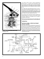
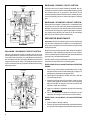
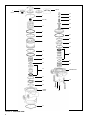
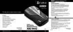
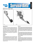
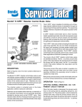
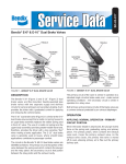
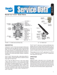
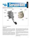
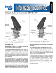
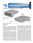
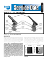
SD-03-826
®
Bendix® E-12™ & E-15™ Dual Brake Valve
TREADLE
MOUNTING
PLATE
UPPER
BODY
ASSEMBLY
PRIMARY
SUPPLY
( SUP-1
)
11
PRIMARY
DELIVERY
( DEL-1
)
21
PRIMARY
SUPPLY
( SUP-2
)
12
SECONDARY
DELIVERY
( DEL-2
)
22
LOWER
BODY
ASSEMBLY
PRIMARY
DELIVERY
( DEL-1
)
21
SECONDARY
DELIVERY
( DEL-2
)
22
EXHAUST
FIGURE 1 - E-12™ AND E-15™ DUAL BRAKE VALVES
DESCRIPTION
E-12™ DUAL
BRAKE VALVE
↑
TREADLE TRAVEL
E-15™ DUAL
BRAKE VALVE
PRIMARY DELIVERY
(PSI)
The E-12™ and E-15™ brake valves are similar in design with
the exception of the rubber spring (9) and spring retainer (7)
located in the upper body. The rubber spring which is used
in the E-12™ brake valve alters the performance of the valve
such that the primary circuit delivers full reservoir pressure
to the spring brakes with less treadle travel than that of the
E-15™ brake valve. See Figure 2 for delivery pressure versus
treadle travel diagram. The greater treadle travel of the E-15™
brake valve yields a more gradual delivery of air to the spring
brakes resulting in a less sensitive “feel” to the driver when a
brake application is made. This characteristic makes the
E-15™ brake valve more adaptable to transit vehicle applications where smooth brake applications contribute to
passenger comfort.
The E-12™ and E-15™ valves are designed such that the
treadle does not sit in an upright position until the air system is built up to full reservoir pressure. The supply pressure
moves the primary piston upward transmitting a mechanical
force to the spring retainer and plunger of the treadle
assembly, causing the treadle to move upright.
PRIMARY DELIVERY
(PSI)
The E-12™ and E-15™ dual brake valves are floor mounted,
treadle operated type brake valves with two separate supply
and delivery circuits for service and secondary braking. The
separation of circuits provides the driver with a graduated
control for applying and releasing the vehicle brakes.
↑
TREADLE TRAVEL
FIGURE 2 - TREADLE TRAVEL VERSUS DELIVERY
PRESSURE
1
The circuits in the E-12™/E-15™ valves are identified as
follows: The no. 1 or primary circuit is that portion of the
valve between the primary piston (2) and the secondary
piston (18); the no. 2 or secondary circuit portion consists
of the area between the secondary piston and the exhaust
cavity.
26
30
32
The supply, delivery and exhaust ports of the E-12™/E-15™
brake valves are identified by designations cast into the valve
body adjacent to their associated port. (See Figure 1). The
primary supply and delivery ports are located in the upper
body portion while the secondary supply and delivery ports
are located in the lower body portion of the valve.
1
The primary circuit of the valve is similar in operation to a
standard single-circuit air brake valve and under normal
operating conditions the secondary circuit is similar in
operation to a relay valve.
31
27
28
29
7
6
8
2
3
4
23
21
22 4
5
20 UPPER BODY
9
15
14
13
12
11
Both the primary and secondary circuits of the brake valve
use a common exhaust protected by an exhaust diaphragm.
OPERATION
18
10
19
17
LOWER BODY
10
12
11
13
14
15
25
24
FIGURE 3 - E-12™ DUAL BRAKE VALVE CROSS
SECTIONAL VIEW
APPLYING: NORMAL OPERATION-PRIMARY
CIRCUIT PORTION
When the brake treadle (26) is depressed, the plunger (27)
exerts a force on the spring retainer (7), graduation spring
(8) and primary piston (2). The primary piston, which contains the exhaust valve seat closes the primary circuit
exhaust valve. As the exhaust valve closes the inlet valve for
the primary circuit moves off of its seat allowing the air from
the supply port of the primary circuit to flow out the delivery
port of the same circuit.
MV-3™
MODULE
TP-5™ TRACTOR
PROTECTION
TRAILER
CONTROL
VALVE
SLACK
ADJUSTER
SPRING
BRAKES
SLACK
ADJUSTER
BRAKE
CHAMBER
DUAL BRAKE
VALVE
DOUBLE
CHECK
VALVE
QUICK
RELEASE
VALVE
AIR DRYER
BP-R1™
BOBTAIL
PROPORTIONING
VALVE
SUPPLY
RESERVOIR
COMPRESSOR
#1 SERVICE
RESERVOIR
FIGURE 4 - TYPICAL PIPING SCHEMATIC
2
#2 SERVICE
RESERVOIR
PLUNGER
FORCE
7
PLUNGER
FORCE
2
2
8
SUP-1
SUP-1
DEL-1
DEL-1
18
DEL-2
SUP-2
DEL-2
SUP-2
EXHAUST
EXHAUST
FIGURE 5 - APPLYING - NORMAL OPERATION
FIGURE 6 - APPLYING - FAILURE IN THE PRIMARY
CIRCUIT
APPLYING: NORMAL OPERATIONSECONDARY CIRCUIT PORTION
BALANCED: PRIMARY CIRCUIT PORTION
The relay piston moves down with the primary piston and
closes the secondary circuit exhaust. When the inlet valve
in the primary portion of the valve is moved off its seat, air
passes through the bleed passage in the lower portion of
the upper body and enters the relay piston cavity. The air
moves the relay piston (18) downward and opens the secondary inlet valve, allowing the air from the secondary supply
to flow out the delivery port of the same circuit.
When the primary delivery pressure acting upon the primary
piston (2), equals the resultant mechanical force of the brake
treadle application, the primary piston will close preventing
further air flow from the supply to the delivery port of the
brake valve. The exhaust valve remains closed preventing
the escape of air through the exhaust port.
PLUNGER
FORCE
2
7
APPLYING: LOSS OF AIR IN THE PRIMARY
CIRCUIT
If air is lost in the primary circuit, the valve will function as
follows: As the brake pedal is depressed and no air pressure is present in the primary circuit, the primary piston (2)
will mechanically move the relay piston closing the secondary exhaust and opening the inlet valve of the same circuit
allowing air flow from the secondary supply to its associated delivery port.
APPLYING: LOSS OF AIR IN THE SECONDARY
CIRCUIT
8
SUP-1
DEL-1
18
DEL-2
SUP-2
If the air is lost in the secondary circuit, the primary circuit
will function as described above under Normal Operation:
Primary circuit portion.
EXHAUST
FIGURE 7 - APPLYING - FAILURE IN THE SECONDARY
CIRCUIT
3
PLUNGER
FORCE
RELEASING: PRIMARY CIRCUIT PORTION
When the force on the brake treadle is released, the mechanical force is removed from the graduation spring (8) and
the primary piston (2). Air pressure in the delivery circuit
moves the primary piston exhaustive valve, allowing air pressure in the primary piston to exhaust through the exhaust
port.
2
SUP-1
RELEASING: SECONDARY CIRCUIT PORTION
DEL-1
SUP-2
DEL-2
When the brake treadle is released, air is exhausted from
the primary circuit side of the relay piston through the bleed
passage. Air pressure in the delivery side of the secondary
circuit moves the relay piston upward, opening the secondary exhaust valve allowing air pressure in the secondary
delivery line to exhaust out the exhaust port.
PREVENTIVE MAINTENANCE
Important: Review the warranty policy before performing
any intrusive maintenance procedures. An extended warranty may be voided if intrusive maintenance is performed
during this period.
EXHAUST
FIGURE 8 - BALANCED POSITION
BALANCED: SECONDARY CIRCUIT PORTION
When the air pressure on the secondary side of the relay
piston approaches the pressure being delivered on the primary side of the relay piston, the relay piston moves closing
the secondary inlet valve preventing further air flow from the
supply line through the valve. The exhaust remains closed
as the secondary delivery pressure balances the primary
delivery pressure.
Because no two vehicles operate under identical conditions,
maintenance and maintenance intervals will vary. Experience is a valuable guide in determining the best maintenance
interval for any one particular operation.
Visually check for physical damage to the brake valve such
as broken air lines and broken or missing parts.
EVERY 3 MONTHS, 25,000 MILES OR 900 OPERATING
HOURS:
1. Remove any accumulated contaminates such as dirt
and gravel from the heel of the treadle (26), plunger (27)
plunger boot (28) and mounting plate (29).
PLUNGER
FORCE
2
2. Use a light oil, lubricate the treadle roller (30), roller pin
(31) and hinge pin (32).
SUP-1
3. Inspect the plunger boot (28) for cracks, holes or deterioration and replace if necessary. Also check mounting
plate and treadle for integrity, wear and corrosion and
replace or repair as necessary.
8
DEL-1
4. Apply 2 to 4 drops of oil between plunger and mounting
plate - do not over oil!
5. Check for excessive leakage as described in the
Operation & Leakage Checks section of this manual.
DEL-2
SUP-2
EVERY YEAR, 100,000 MILES, OR 3,600 OPERATING
HOURS:
1. Perform steps 1 through 4 above.
EXHAUST
FIGURE 9 - RELEASED MODE
4
2. Perform the operation and leakage checks described in
the Operation & Leakage Checks section of this manual.
OPERATION & LEAKAGE CHECKS
GENERAL
A change in vehicle braking characteristics or a low pressure warning may indicate a malfunction in one or the other
brake circuit, and although the vehicle air brake system
may continue to function, the vehicle should not be operated until the necessary repairs have been made and both
braking circuits, including the pneumatic and mechanical
devices are operating normally. If the brake valve does
not function as described above or leakage is excessive,
it is recommended that it be replaced with a new or remanufactured unit available at Bendix outlets. Always check the
vehicle brake system for proper operation after performing
brake work and before returning the vehicle to service.
OPERATING CHECK
Check the delivery pressure of both No. 1 and No. 2 circuits
using test gauges known to be accurate.
Note: The treadle or pedal will not be in a “normal” released
position until the air brake system is pressurized. The pedal
or treadle will rise to its normal release position as the brake
system is pressurized from 0 psi.
Depress the treadle to several positions between the fully
released and fully applied positions and check the delivered
pressure on the test gauges to see that it varies equally and
proportionately with the movement of the brake pedal.
After a full application is released, the reading on the test
gauges should fall off to zero promptly. It should be noted
that the No. 1 circuit delivery pressure will be about 4 psi
greater than the No. 2 circuit delivery pressure with both
supply reservoirs at the same pressure. This in normal for
this valve.
LEAKAGE CHECK
Make and hold a pressure application of 20 psi.
Coat the exhaust port and body of the brake valve with a
soap solution.
Leakage permitted is a 1" bubble in 3 seconds in both the
applied and released positions.
WARNING! PLEASE READ AND FOLLOW
THESE INSTRUCTIONS TO AVOID
PERSONAL INJURY OR DEATH:
When working on or around a vehicle, the following
general precautions should be observed at all times.
1. Park the vehicle on a level surface, apply the
parking brakes, and always block the wheels.
Always wear safety glasses.
2. Stop the engine and remove ignition key when
working under or around the vehicle. When
working in the engine compartment, the engine
should be shut off and the ignition key should be
removed. Where circumstances require that the
engine be in operation, EXTREME CAUTION should
be used to prevent personal injury resulting from
contact with moving, rotating, leaking, heated or
electrically charged components.
3. Do not attempt to install, remove, disassemble or
assemble a component until you have read and
thoroughly understand the recommended
procedures. Use only the proper tools and observe
all precautions pertaining to use of those tools.
4. If the work is being performed on the vehicle’s air
brake system, or any auxiliary pressurized air
systems, make certain to drain the air pressure from
all reservoirs before beginning ANY work on the
vehicle. If the vehicle is equipped with an AD-IS™
air dryer system or a dryer reservoir module, be
sure to drain the purge reservoir.
5. Following
the
vehicle
manufacturer’s
recommended procedures, deactivate the electrical
system in a manner that safely removes all
electrical power from the vehicle.
6. Never exceed manufacturer’s recommended
pressures.
7. Never connect or disconnect a hose or line
containing pressure; it may whip. Never remove a
component or plug unless you are certain all
system pressure has been depleted.
8. Use only genuine Bendix ® replacement parts,
components and kits. Replacement hardware,
tubing, hose, fittings, etc. must be of equivalent
size, type and strength as original equipment and
be designed specifically for such applications and
systems.
9. Components with stripped threads or damaged
parts should be replaced rather than repaired. Do
not attempt repairs requiring machining or welding
unless specifically stated and approved by the
vehicle and component manufacturer.
10. Prior to returning the vehicle to service, make certain all components and systems are restored to
their proper operating condition.
VEHICLE PREPARATION
1. Park the vehicle on a level surface and block the wheels
and/or hold the vehicle by means other than the air
brakes.
2. Drain the air pressure from all vehicle reservoirs.
VALVE REMOVAL
1. Identify and mark or label all air lines and their respective connections on the brake valve to facilitate ease of
installation. Disconnect all air lines.
2. Mark the relationship of the valve body to the mounting
plate then remove the valve from its mounting on the
vehicle.
5
6
7 (E-15)
7
(E-12)
23
1
21
9 (E-12)
22
20
8
18
3
19
4
10
2
11
12
4
13
5
14
15
15
14
13
LOWER BODY
12
16
11
10
UPPER
BODY
17
FIGURE 10 - EXPLODED VIEW
6
25
24
DISASSEMBLY
The following disassembly and assembly procedure is presented for reference purposes and presupposes that a major
rebuild of the brake valve is being undertaken. Several replacement parts and maintenance kits are available which
do not require full disassembly. The instructions provided
with these parts and kits should be followed in lieu of the
instructions presented here.
Caution: The brake valve may be lightly clamped in a
bench vise during disassembly, however, over clamping
will result in damage to the valve and result in leakage and/
or malfunction. If a vise is to be used, position the valve so
that the jaws bear on the delivery and supply ports on
opposing sides of the valve’s upper body.
1. Remove all air line fittings and plugs.
2. Mark the relationship of the upper and lower body (a
scribed line can be used) then remove the four cap
screws (16) that secure the lower body to the upper
body. Separate the two body halves and remove and
discard the o-ring (17).
3. Pull the secondary piston (18) out of the upper body and
remove and discard the o-rings (19 & 20) from it.
4. Remove and discard the special beveled retaining ring
(10) from the lower body while manually holding and
compressing the valve seat (11) in place.
5. Slowly release the valve seat (11), allowing it to rise out
of the body. Remove the valve seat (11) then remove and
discard the o-ring (12).
6. Remove and discard the valve assembly (13) along with
its o-ring (15) from the lower body. Remove the valve
assembly return spring (14).
7. Carefully remove and discard the exhaust diaphragm
retainer (24) and exhaust diaphragm (25) from the lower
body.
Note: Some E-12™ & E-15™ brake valves have threaded
exhaust ports in lieu items 24 & 25.
8. Using finger force, push the piston (2) into the body until
the piston retaining ring (1) is fully visible. Remove the
piston retaining ring (1), taking care not to damage the
piston bore in the body.
9. Gently tap the body on a soft surface to remove the
piston (2). Remove and discard the o-rings (3 & 5) and
both wear rings (4) from the piston (2).
10. Place the piston on a flat surface and using finger force,
depress and hold the spring retainer (7), then remove
and discard the retaining ring (6) from the piston (2).
11. Gently release the spring retainer (7), allowing it to rise
out of the piston. Remove the spring retainer (7) and
graduating spring (8) from the piston (2).
12. Remove and discard the rubber spring (9) from the
interior of the piston (2).
Note: The rubber spring (9) is installed in the E-12™
brake valve only.
13. Remove and discard the special beveled retaining ring
(10) from the piston (2) while manually holding and
compressing the valve seat (11) in place.
14. Slowly release the valve seat (11), allowing it to rise out
of the piston (2). Remove the valve seat (11), then
remove and discard the o-ring (12).
15. Remove and discard the valve assembly (13) along with
its o-ring (15) from the piston (2). Remove the valve
assembly return spring (14).
CLEANING & INSPECTION
1. Using mineral spirits or an equivalent solvent, clean and
thoroughly dry all metal parts.
2. Inspect the interior and exterior of all metal parts that
will be reused for severe corrosion, pitting and cracks.
Superficial corrosion and or pitting on the exterior portion of the upper and lower body halves is acceptable.
3. Inspect the bores of both body halves for deep scuffing
or gouges.
4. If the primary piston (2) is to be reused make certain
that vents “A & B” are open and free of obstructions.
5. Make certain vent “C” is open in the upper body of the
valve.
6. Inspect the pipe threads in both body halves. Make
certain they are clean and free of thread sealant.
7. Inspect the treadle or pedal assembly and mounting plate
which attaches to the basic valve. Make certain that
the treadle or pedal roller turns freely and is lightly
lubricated.
Note: Some treadle/pedal assemblies, not furnished by
Bendix, do not employ a roller in which case make certain the mechanism in use moves across the plunger
smoothly without binding or sticking. Inspect the plunger
for excessive scuffing and wear. Check the plunger bore
in the mounting plate for excessive wear as exhibited by
“egg shaping.” Inspect the mounting plate for severe
corrosion paying particular attention to the area around
the pedal or treadle fulcrum pin bores.
8. When applicable (in use), check the rubber boot installed
between the plunger and mounting plate for deterioration or cracking. Replace if necessary.
9. Inspect all air line fittings and plugs for corrosion. Clean
all old thread sealant from the pipe threads.
Any valve or treadle assembly component exhibiting a condition described in inspection steps 1 to 9 should be discarded
and replaced before proceeding.
7
1. Using the lubricant provided (Bendix Pc. No. 291126),
lightly coat all o-rings, o-ring bores and grooves. Lightly
lubricate the primary piston (2) bore into which the graduating spring (8) is installed.
While manually depressing and holding the plunger and
spring on the piston, slide the plunger and spring
retainer (23) into place so that it secures both the plunger
and spring to the piston. Make certain the retainer flanges
are securely around piston lip and plunger groove.
2. Place the primary piston (2) on a flat surface and install
the rubber spring (9) and metal graduating spring (8).
12. Install the o-rings (19 & 20) on the secondary piston
(18).
Note: The rubber spring (9) is used in the E-12™ brake
valve only. If a rubber spring was not removed in disassembly step 11, discard this component - do not
install it.
13. Install the exhaust diaphragm (25) on the lower body
and secure it using diaphragm retainer (24).
3. Install the proper graduating spring retainer (7) on top of
the graduating spring (8) making certain that the side
with the high circular protrusion is away from the spring.
14. Install the valve spring (14) in the lower body, then install
the valve assembly (13) in the spring.
ASSEMBLY
4. Manually depress and hold the spring retainer (7) in the
piston (2), then install the retaining ring (6) making certain it is completely seated in its groove in the piston
(2).
5. Install the o-rings (15) on both valve assemblies (13).
6. Install the valve spring (14) in the piston (2), then install
the valve assembly (13) in the spring.
Note: Some E-12™ & E-15™ brake valves have threaded
exhaust ports in lieu items 24 & 25.
15. Install the o-ring (12) into the o-ring groove of piston (2),
then install the valve seat (11) on the valve assembly
(13). Gently depress and hold the valve seat in the lower
body while installing the special beveled retaining ring
(10).
Important: The beveled retaining ring (10) must be installed with its flat side against the valve seat (11) and
its beveled side visible.
Make certain the beveled retaining ring (10) is completely
seated in its groove in the lower body.
7. Install the o-ring (12) into the o-ring groove of piston (2),
then install the valve seat (11) on the valve assembly
(13). Gently depress and hold the valve seat in the piston (2) while installing the special beveled retaining ring
(10).
16. Install the assembled secondary piston (18) in the upper body making certain that the o-rings (19 & 20) are
not damaged in the process.
Important: The beveled retaining ring (10) must be installed with its flat side against the valve seat (11) and
its beveled side visible. Make certain the beveled retaining ring (10) is completely seated in its groove in the
piston (2).
17. Install the o-ring (17) on the upper body. Join the assembled upper and lower body halves noting the
relationship marked in Disassembly step 2. Secure the
body halves together using the four 1/4" cap screws (16)
and torque to 30 to 60 pound inches.
8. Install the o-rings (3 & 5) on the primary piston (2), then
install the wear rings (4) in the o-ring grooves next to the
o-rings. Make certain that one flange of the angular wear
ring (4) is in the o-ring groove, while the opposite flange
extends away from the end of the piston (2) and toward
the center. The wear ring flange must not cover or overlap either o-ring.
18. If the brake valve is firewall mounted, install the pedal
mounting plate on the basic brake valve noting the relationship marked during Disassembly step 2. Secure the
mounting plate to the valve using the three 5/16" cap
screws and torque to 80 to 120 pound inches.
9. Carefully insert the assembled primary piston (2), valve
end first, into the upper valve body until the piston
retaining ring groove in the body is visible. Make certain
the o-rings (3 & 5) and wear rings (4) are not damaged in
the process. Do not force the piston. If substantial
resistance is encountered, check for proper installation
of the wear rings.
10. Install the piston retaining ring (1) in its groove in the
upper body, making certain it is fully seated in the groove.
19. Install all air line fittings and plugs making certain
thread sealant material does not enter the valve.
VALVE INSTALLATION
1. Install the assembled brake valve on the vehicle.
2. Reconnect all air lines to the valve using the identification made during Valve Removal step 1.
3. After installing the brake valve assembly, perform the
Operation & Leakage Checks before placing the vehicle
in service.
11. Install the plunger (21) in its return spring (22). Install
the spring and plunger on the secondary piston (18).
8
BW1622 © 2004 Bendix Commercial Vehicle Systems LLC. All rights reserved. 3/2004 Printed in U.S.A.