1
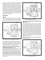
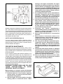
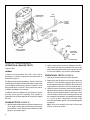
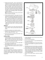
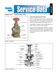
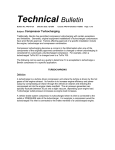
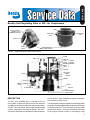
SD-01-3408
®
Bendix® Inlet Regulating Valve or IRV™ for Compressors
VENT
OUTLET FLANGE
(MATES TO
COMPRESSOR INLET)
MOUNTING
HOLE
MOUNTING
HOLE
OUTLET
SAFETY
VALVE
TURBOCHARGER
SUPPLY PORT 3/4” NPT
FIGURE 1 - COMPRESSOR INLET REGULATING VALVE
BODY
O-RING
O-RING OR
VALVE &
U-CUP
PISTON
PISTON
HOUSING ASSEMBLY
O-RING
VALVE
O-RING
OUTLET
VALVE SEAT
O-RING
SPRING
VALVE
SAFETY SPRING
VALVE
EXHAUST PLUG
SPACER
O-RING
CAP NUT
TURBOCHARGER
SUPPLY PORT
FIGURE 2 - INLET REGULATING VALVE
DESCRIPTION
The IRV™ inlet regulating valve is intended for use on
multi-cylinder compressors which receive their induction
air supply from the pressure side of the engine turbocharger.
The IRV™ valve may not be used in conjunction with single
cylinder compressors including the Bendix® BX-2150™
compressor. Generally mounted directly at the compressor
air inlet, the IRV™ valve is designed to regulate compressor
inlet pressure to 10 psi or less.
The cast aluminum body incorporates an outlet flange which
is capable of mating with all Bendix compressor inlet flanges
except that of the Tu-Flo® 300 compressor. A 3/4 inch female
pipe thread in the IRV™ valve cap nut facilitates connection
to the engine induction system or turbocharger. High
1
temperature o-rings, seals, seats, and lubricant are used
throughout the IRV™ valve to provide compatibility with
incoming turbocharger air temperatures up to 250°F. The
unitized valve and piston assembly consists of the piston
housing, two o-rings and control piston with its permanently
affixed valve plate. The cavity below the piston is vented to
atmosphere. The ring spacer holds the piston housing in
place and rests on the supply cap nut along with the valve
spring. The steel cap nut contains the supply port and retains
an o-ring which serves as the valve seat. A hex socket plug
with a through drilled vent along with a spring and steel ball
valve comprise the safety valve.
PISTON
VALVE
PLATE
OUTLET
TO
COMPRESSOR
SEAT
SPRING
OPERATION
TURBOCHARGER
SUPPLY
GENERAL
The IRV™ valve maintains a low pressure at the compressor
inlet (10 psi or less) regardless of turbocharger supply air
pressure. The air flow through the IRV™ valve is throttled by
COMPRESSOR LOADED HIGH TURBOCHARGER
PRESSURE (Figure 4)
PISTON
VALVE
PLATE
SPRING
SEAT
OUTLET
TO
COMPRESSOR
FIGURE 4 - COMPRESSOR LOADEDHIGH TURBOCHARGER PRESSURE
TURBOCHARGER
SUPPLY
FIGURE 3 - COMPRESSOR EITHER LOADED OR
UNLOADED WITH LOW TURBOCHARGER PRESSURE
Air at turbocharger supply pressure is continually supplied
to the chamber above the IRV™ valve piston. At pressures
above 5 psi the force on the piston is sufficient to partially
close the valve. With the compressor loaded (compressing
air) the resulting pressure drop across the valve lowers the
delivery pressure to the compressor. This lower pressure is
effective over the upper surface of the valve plate, tending to
open the valve. The pressure drop across the valve increases
with increased compressor flow (higher compressor RPM).
The position of the valve is thus affected by both turbo
supply pressure and compressor air demand. High turbo
supply pressure coupled with low compressor air demand
will tend to close the valve.
COMPRESSOR UNLOADED HIGH TURBOCHARGER
PRESSURE (Figure 5)
the valve which varies in position from fully open to closed.
Valve position and, therefore, the degree of throttling is
controlled by both turbocharger supply pressure and
compressor air flow demand. The operation of the IRV™ valve
is described for each of four functional conditions.
COMPRESSOR EITHER LOADED OR UNLOADED LOW
TURBOCHARGER PRESSURE (Figure 3)
For both loaded and unloaded compressor operation at low
turbocharger pressure (Less than 5 psi) the IRV™ valve
remains fully open. Air is supplied to the compressor at
turbo supply pressure. The position of the piston/valve plate
assembly is determined by the pressure forces acting on
the top of the piston, on the upper and lower valve plate
surfaces, and by the spring force. At low supply pressure
the thrust of the pressure forces is insufficient to overcome
the spring force.
2
PISTON
VALVE
PLATE
SEAT
OUTLET
TO
COMPRESSOR
SPRING
TURBOCHARGER
SUPPLY
FIGURE 5 - COMPRESSOR UNLOADEDHIGH TURBOCHARGER PRESSURE
OUTLET
TO
COMPRESSOR
3.
4.
TURBOCHARGER
SUPPLY
FIGURE 6 - SAFETY VALVE OPERATION
With the compressor unloaded air demand ceases and the
IRV™ valve closes as turbo supply pressure exceeds 5 psi.
The valve will close at a pressure between 5 and 10 psi and
remain closed at higher pressures, allowing only a minute
flow to compensate for compressor piston ring blow-by in
the unloaded mode. At the compressor inlet, pressure is
maintained at less than 10 psi.
5.
6.
7.
SAFETY VALVE OPERATION (Figure 6)
If for any reason pressure at the compressor inlet is
excessive, the safety valve located in the IRV™ valve outlet
flange will open. Pressure in excess of 18 psi will allow air
to be exhausted to atmosphere.
8.
PREVENTIVE MAINTENANCE
Important: Review the Bendix Warranty Policy before
performing any intrusive maintenance procedures. A warranty
may be voided if intrusive maintenance is performed during
the warranty period.
No two vehicles operate under identical conditions, as a
result, maintenance intervals may vary. Experience is a
valuable guide in determining the best maintenance interval
for air brake system components. At a minimum, the IRV™
valve should be inspected every 6 months or 1500 operating
hours, whichever comes first, for proper operation. Should
the IRV™ valve not meet the elements of the operational
tests noted in this document, further investigation and service
of the valve may be required.
WARNING! PLEASE READ AND FOLLOW
THESE INSTRUCTIONS TO AVOID
PERSONAL INJURY OR DEATH:
When working on or around a vehicle, the following
general precautions should be observed at all times.
1. Park the vehicle on a level surface, apply the
parking brakes, and always block the wheels.
Always wear safety glasses.
2. Stop the engine and remove ignition key when
working under or around the vehicle. When
9.
10.
working in the engine compartment, the engine
should be shut off and the ignition key should be
removed. Where circumstances require that the
engine be in operation, EXTREME CAUTION should
be used to prevent personal injury resulting from
contact with moving, rotating, leaking, heated or
electrically charged components.
Do not attempt to install, remove, disassemble or
assemble a component until you have read and
thoroughly understand the recommended
procedures. Use only the proper tools and observe
all precautions pertaining to use of those tools.
If the work is being performed on the vehicle’s air
brake system, or any auxiliary pressurized air
systems, make certain to drain the air pressure from
all reservoirs before beginning ANY work on the
vehicle. If the vehicle is equipped with an AD-IS™
air dryer system or a dryer reservoir module, be
sure to drain the purge reservoir.
Following
the
vehicle
manufacturer’s
recommended procedures, deactivate the electrical
system in a manner that safely removes all
electrical power from the vehicle.
Never exceed manufacturer’s recommended
pressures.
Never connect or disconnect a hose or line
containing pressure; it may whip. Never remove a
component or plug unless you are certain all
system pressure has been depleted.
Use only genuine Bendix ® replacement parts,
components and kits. Replacement hardware,
tubing, hose, fittings, etc. must be of equivalent
size, type and strength as original equipment and
be designed specifically for such applications and
systems.
Components with stripped threads or damaged
parts should be replaced rather than repaired. Do
not attempt repairs requiring machining or welding
unless specifically stated and approved by the
vehicle and component manufacturer.
Prior to returning the vehicle to service, make
certain all components and systems are restored
to their proper operating condition.
1/8” NPT
CONNECTION
COMPRESSOR
INLET
MOUNTING
HOLE(2)
FIGURE 7 - COMPRESSOR INLET ADAPTER PART NO.
236701
3
COMPRESSOR
INLET CAVITY
TEST
GAUGE A
AIR LINE
QUICK
COUPLER
ADAPTER
(236701)
INLET GASKETS
(243430)
TYPICAL
MULTI-CYLINDER
COMPRESSOR
IRV
TEST
GAUGE B
PRESSURE
REGULATING
VALVE
TO SHOP AIR
FIGURE 8 - IRV™ VALVE TEST APPARATUS
OPERATION & LEAKAGE TESTS
(Figures 7 & 8)
GENERAL
In order to test the operation of the IRV™ valve it will be
necessary to install the equipment and apparatus as
illustrated in Figure 8.
The Bendix compressor inlet adapter in Figures 7 and 8 can
be obtained at the nearest Bendix parts outlet. In most cases
the inlet adapter will be required, however, if the IRV™ valve
being tested has a 1/8 inch NPT access port in the area of
its flange, the adapter is not needed.
In addition to the inlet adapter two test gauges of known
accuracy and a pressure regulating valve capable of
graduation in the 5-30 psi range will be required to complete
the tests.
LEAKAGE TESTS (FIGURE 8)
1. With the engine off and vehicle air system pressure above
15 psi, apply 15 psi shop air pressure at the turbo supply
port of the IRV™ valve. When pressure stabilizes on test
gauge ‘A’, proceed to Step 2.
4
2. Using a soap solution check for leakage at the IRV™
valve vent in the body, around the two inch cap nut and
at the exhaust plug of the safety valve. Leakage in excess
of a one inch bubble in one second is unacceptable.
OPERATIONAL TESTS (FIGURE 8)
1. Drain the air pressure from the vehicle reservoirs.
2. Apply 25 psi shop air pressure to the turbo supply port
of the IRV™ valve, start the engine and allow it to run at
an idle (approximately 600-700 RPM). When vehicle air
system pressure rises above 25 psi, proceed to Step 3.
3. Using the pressure regulating valve and test gauge B,
adjust the shop air pressure being delivered to the IRV™
valve in 5 psi increments between 5 and 25 psi. Pause
15-20 seconds at each pressure setting and note that
the compressor inlet pressure, as indicated by test gauge
‘A’, is 12 psi or less. If the pressure exceeds 12 psi
more than momentarily, the IRV™ valve should be repaired
or replaced.
Note: The tests described in this step must be made
with the compressor loaded.
4. Adjust shop air to the IRV™ valve to 5 psi and allow the
compressor to build the vehicle air system pressure to
governor cut-out and note that the compressor unloads.
With the compressor unloaded increase the shop air
pressure to the IRV™ valve in 5 psi increments up to 25
psi. Pause 15-20 seconds at each pressure setting and
note that the compressor inlet pressure as indicated by
test gauge ‘A’ is 12 psi or less. If the pressure exceeds
12 psi more than momentarily, the IRV™ valve should be
repaired or replaced.
Note: The tests described in this step must be made
with the compressor unloaded.
5. Test the function of the IRV™ valve safety. Turn off the
engine and simultaneously apply shop air pressure to
the IRV™ valve turbo supply port and to the compressor
inlet (through the inlet adapter 236701). Beginning at 5
psi, slowly raise the pressure at both locations
simultaneously until an exhaust of air is heard at the
IRV™ valve’s safety valve. Note the pressure on gauge
‘A’ when the exhaust is heard. If exhaust occurs below
18 psi or above 25 psi, the IRV™ valve must be repaired
or replaced.
BODY
VALVE
O-RING
O-RING
SPRING
EXHAUST
PLUG
VALVE &
PISTON
ASSEMBLY
SPRING
SPACER
REMOVAL
1. Park the vehicle on a level surface and block the wheels
and/or hold the vehicle by means other than the air
brakes.
O-RING
VALVE SEAT
(O-RING)
2. Drain the air pressure from all vehicle reservoirs.
3. Disconnect the turbocharged air line at the 3/4 inch
NPT turbo supply port of the IRV™ valve.
4. Remove the two cap screws that secure the IRV valve,
then remove the valve itself.
CAP NUT
™
INSTALLATION
FIGURE 9 - INLET REGULATING VALVE
1. Install a new gasket on the mounting flange of the IRV™
valve and using two cap screws secure the IRV™ valve.
Note: If 5/16 inch cap screws are used to secure the
IRV™ valve to the compressor inlet, torque the cap screws
to between 125 and 150 pound inches.
1. Using an adjustable or two inch wrench remove the cap
nut from the body.
2. Reconnect the turbocharged air line to the 3/4 inch NPT
turbo supply port of the IRV™ valve.
4. Taking care not to damage the roll crimp of the cap nut,
remove the small diameter o-ring which serves as the
valve seat.
3. Before placing the vehicle in service, close all reservoir
drain cocks and build air system pressure to governor
cut-out.
DISASSEMBLY (FIGURE 9)
The following disassembly instructions are presented for
reference purposes. Actual disassembly should not be
undertaken without having the necessary maintenance kit
and instructions available. Refer to Figure 9 throughout
disassembly.
2. Remove the spring and spacer.
3. Remove the large diameter o-ring located beneath the
hex head of the cap nut.
5. Gently tap the open end of the valve body on a nonmetallic
surface in order to remove the valve and piston assembly.
6. Remove the large and small diameter o-rings from the
exterior of the valve and piston assembly. NOTE: No
further disassembly of the valve and piston assembly
should be attempted. The detail parts of this assembly
are NON-SERVICEABLE.
7. Using a 3/16 inch Allen wrench, remove the exhaust
plug.
8. Remove the valve spring and valve.
5
CLEANING & INSPECTION
ASSEMBLY
1. Using mineral spirits, clean and thoroughly dry all metal
parts with the EXCEPTION of the VALVE AND PISTON
ASSEMBLY. The valve and piston assembly contain
o-rings, therefore, wipe the exterior of the exposed areas
avoiding the bore in which the piston slides since a
special high temperature lubricant is used on that
surface.
The appropriate lubricant is packaged in Bendix maintenance
kits and should be used as directed in the kit instruction
sheet. Refer to Figure 9 throughout assembly.
2. Using a thin wire make certain that the vent holes in the
IRV™ valve body and valve and piston assembly are open.
3. Check all metal parts for severe corrosion, pitting and
cracks. Pay particular attention to the valve springs and
valve surfaces. Superficial corrosion and shallow pitting
on the exterior of the cap nut and body is acceptable.
1. Lubricate the interior bore of the body and the o-ring
grooves of the valve and piston assembly.
2. Lubricate and install the large and small diameter o-rings
on the valve and piston assembly.
3. Carefully insert the valve and piston assembly into the
body, making certain that it is completely seated and
the valve plate remains visible.
4. Carefully work the small diameter o-ring, which serves
as the valve seat, into the cap nut groove. When properly
installed, this o-ring is evenly retained by the rolled over
crimped edges of the cap nut groove. IMPORTANT: Do
not Lubricate this o-ring or the cap nut groove in
which it is installed.
5. Lubricate the cap nut groove for the large diameter
o-ring. Lubricate, then install the large diameter o-ring
on the cap nut.
6. Install the spacer then the spring in the valve body.
7. Install the cap nut in the body and torque it to between
58 and 72 pound feet.
8. Install the safety valve and valve spring in the IRV™ valve
body. Using a 3/16 inch Allen wrench, install the exhaust
plug.
9. Perform the operation and leakage tests before placing
the valve in service.
6
BW1552 © 2004 Bendix Commercial Vehicle Systems LLC All rights reserved. 3/2004 Printed in U.S.A.