1
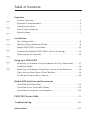
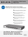
OmniView® KVM-Switch
PRO2 PS/2
Control
PRO2 PS/2 Switch with On-Screen Display
Control up to 16 computers from one PS/2 console!
EN
Switch with On-Screen Display - Control
up to 16 computers from one PS/2 console
FR
Switch avec affichage à l’écran Contrôlez jusqu’à 16 ordinateurs à partir
d’une console PS/2!
DE
Masterswitch mit Bildschirmmenü Zur Kontrolle von bis zu 16 Computern
mit nur einer PS/2-Konsole !
NL
Switch met On-Screen Display - Tot 16
computers beheren met slechts één
PS/2-console !
ES
Conmutador con OSD (menús en la
pantalla) - Controla hasta 16 ordenadores
desde una sola consola PS/2!
IT
Switch con On-Screen Display Per gestire fino a 16 computer
da una console PS/2!
User Manual • Manuel de l’utilisateur
Benutzerhandbuch • Handleiding
Manual del usuario • Manuale utente
F1DA104Pea
F1DA108Pea
F1DA116Pea
Table of Contents
1
2
3
4
5
6
7
8
9
10
Overview
Feature Overview . . . . . . . . . . . . . . . . . . . . . . . . . . . . . . . . . . . . . 2
Equipment Requirements . . . . . . . . . . . . . . . . . . . . . . . . . . . . . . . 3
Operating Systems . . . . . . . . . . . . . . . . . . . . . . . . . . . . . . . . . . . 4
Unit Display Diagrams . . . . . . . . . . . . . . . . . . . . . . . . . . . . . . . . . 5
Specifications . . . . . . . . . . . . . . . . . . . . . . . . . . . . . . . . . . . . . . . 7
Installation
Pre-Configuration . . . . . . . . . . . . . . . . . . . . . . . . . . . . . . . . . . . . 8
Step-by-Step Installation Guide . . . . . . . . . . . . . . . . . . . . . . . . . . 9
Single PRO2 PS/2 Installation . . . . . . . . . . . . . . . . . . . . . . . . . . 10
Connecting Multiple PRO2 PS/2s (Daisy-Chaining) . . . . . . . . . . 12
Powering up the Systems. . . . . . . . . . . . . . . . . . . . . . . . . . . . . . 16
Using your PRO2 PS/2
Selecting a Computer Using Keyboard Hot Key Commands . . . . 17
AutoScan Mode . . . . . . . . . . . . . . . . . . . . . . . . . . . . . . . . . . . . . 18
Selecting a Computer Using Direct-Access Port Selectors . . . . . 18
Bank Up and Bank Down Scroll Buttons . . . . . . . . . . . . . . . . . . . 18
On-Screen Display Menu Control . . . . . . . . . . . . . . . . . . . . . . . . 20
Belkin KVM Switches and Accessories
OmniView KVM Switches . . . . . . . . . . . . . . . . . . . . . . . . . . . . . . 23
OmniView All-In-One KVM Cables . . . . . . . . . . . . . . . . . . . . . . . 25
OmniView Accessories and Adapters
. . . . . . . . . . . . . . . . . . . . 26
PRO2 PS/2 Series FAQs . . . . . . . . . . . . . . . . . . . . . . . . . . . . . . . . 27
Troubleshooting . . . . . . . . . . . . . . . . . . . . . . . . . . . . . . . . . . . . . 30
Information . . . . . . . . . . . . . . . . . . . . . . . . . . . . . . . . . . . . . . . . . 34
Overview
1
Offering intuitive port indicators, direct-access port selectors, high video
resolution support, and flash upgradeable firmware.
5
The PRO2 PS/2 also comes with an unparalleled Belkin Three-Year
Warranty.
6
This manual will provide details about your new PRO2 PS/2, from
installation and operation to troubleshooting—in the unlikely event of a
problem.
7
For quick and easy installation, please refer to the Quick Installation
Guide included in your PRO2 PS/2 packaging.
Package Contents
• OmniView PRO2 PS/2 Series KVM Switch
• Adjustable Rack-mount Brackets with Screws
• USB Flash Cable
• User Manual
• Quick Installation Guide
• 12-Volt DC, 1-Amp Power Supply
• Registration Card
1
2
3
4
8
9
10
section
Congratulations on your
purchase of this Belkin
OmniView PRO2 PS/2
Series KVM Switch
(the PRO2 PS/2). Our diverse
line of KVM solutions exemplifies the Belkin commitment to delivering
high-quality, durable products at a reasonable price. Designed to give
you control over multiple computers and servers from one console, Belkin
PRO2 PS/2s come in a variety of capacities suitable for all configurations,
large or small.
Overview
section
1
2
3
4
5
6
7
8
9
10
The PRO2 PS/2s allow you to control up to a maximum of 256 PS/2
computers with one keyboard, monitor, and mouse. They support PS/2
input devices (keyboard and mouse) as well as VGA, SVGA, XGA, and
XGA-2 video.
Feature Overview
Hot Keys:
Hot key functionality allows you to select a desired port using
designated key commands. By using a simple hot key sequence
on your keyboard, selecting one computer from as many as 256
computers is instantaneous. For a listing of complete hot key
instructions and commands, see pages 17-19
AutoScan:
The AutoScan feature allows you to set your PRO2 PS/2 to scan and
monitor the activities of all operating computers connected to the
switch—one by one. The time interval allotted for each computer can
be defined or adjusted through the On-Screen Display (OSD) menu.
For complete instructions on AutoScan usage, please refer to page 18.
Video Resolution:
Through a 400MHz bandwidth, the PRO2 PS/2s support video
resolutions of up to 2048x1536@85Hz. To preserve signal integrity at
these higher resolutions, your PRO2 PS/2 requires 75-Ohm coaxial
VGA cabling
Flash Upgrade:
Flash upgradeable firmware allows you to install the latest firmware
for your PRO2 PS/2. This enables your PRO2 PS/2 to maintain
consistent compatibility with the latest devices and computers.
Firmware upgrades are free for the life of your PRO2 PS/2. Refer to
the enclosed flash upgrade instruction document or visit us at belkin.
com for complete upgrade information and support.
On-Screen Display (OSD):
The OSD feature simplifies server management by allowing you to
assign individual names to each connected server throughout the
system. It provides a visual means of switching between computers
and setting the time interval for the AutoScan function.
2
Overview
Direct-access port selectors, located conveniently on the front panel of
the PRO2 PS/2, allow for simple, manual port-selection. Each button
controls a port.
2
3
LED Display:
An LED display on the face of the PRO2 PS/2 serves as a status monitor.
An LED next to each direct-access port selector illuminates to indicate
that the console currently controls the corresponding computer. As a port
selector is pushed, the LED next to it will light up. A flashing port LED
indicates that there is no computer connected to that port.
Seven-Segment LED Display:
When daisy-chaining multiple PRO2 PS/2s together, the seven-segment
LED display serves as a quick indicator of the selected BANK.
Equipment Requirements Cables:
To connect to the PRO2 PS/2, each PS/2 computer requires one VGA
cable, one PS/2 keyboard cable, and one PS/2 mouse cable. Keyboard
and mouse cables must have PS/2 male-to-PS/2 male connectors.
Video resolution support of up to 2048x1536@85Hz requires use of a
75-Ohm coaxial VGA cable to preserve signal integrity. VGA cables must
have HDDB15 female-to-HDDB15 male connectors.
Belkin highly recommends that you use OmniView All-In-One PRO Series
Plus Cables. These cables offer the highest quality possible to ensure
optimal data transmission. All-In-One Cables are molded together for
a clean and organized setup; are double-shielded to reduce EMI/RFI
interference; have strain-relief construction for added durability; come
with a ferrite bead for noise immunity; and include PC99 color-coded
connectors for easy identification and connection. The PRO Series Plus
Cables include an industry-standard, 14-pin, coaxial VGA cable and
nickel-plated connectors for high-resolution applications.
3
4
5
6
7
8
9
10
section
1
Front-Panel Push Button:
Overview
section
1
2
3
4
5
6
The following cables are recommended for your PRO2 PS/2:
OmniView All-In-One PRO Series Plus
F3X1105b-XX (PS/2 Style)
(-XX denotes length in feet)
Operating Systems
OmniView PRO2 PS/2 Series KVM Switches are for use on CPUs
using:
Platforms:
7
•
•
•
•
8
• Supports 101-/102-/104-key keyboards
9
Mice:
10
Windows ® 95/98/2000/Me/NT ® /XP
DOS
Turbolinux ® and all Linux ® distributions
Novell ® NetWare ® 4.x/5.x
Keyboards:
• Microsoft ® system-compatible PS/2 mice having 2, 3, 4, or 5 buttons
• Microsoft system-compatible PS/2 wireless or optical mice
Monitor:
• VGA
• SVGA
• MultiSync ®
4
Overview
BANK DIP switch
(may be located on
the back in some
models)
FLASH DIP switch
(may be located on
the back in some
models)
2
3
4
�
�
�
�
�
�
��
����
��
5
�
�
�
�
� ��� �
6
7
8
9
10
5
section
1
Side View of the PRO2 PS/2:
Overview
section
1
2
3
Front View of the PRO2 PS/2:
F1DA108Pea
Autoscan button
LED for selected
port identification
7-segment LED
for selected BANK
identification
4
5
6
7
8
Direct-access
port selectors
Manual BANK
scroll buttons
9
10
Back View of the PRO2 PS/2:
F1DA108Pea
Console VGA
Computer VGA port
Console PS/2 mouse/keyboard ports
Flash Upgrade port
Computer PS/2
mouse/keyboard ports
Master Input/Slave Output
Slave Input
6
DC power jack
Overview
Part No.: F1DA104Pea, F1DA108Pea & F1DA116Pea
Power: 12-Volt DC, 1-Amp power adapter with center-pin positive
polarity Daisy-Chain: Maximum of 16 KVM Switches
Computer Connections Supported:
4 (F1DA104Pea)
8 (F1DA108Pea)
16 (F1DA116Pea)
Keyboard Emulation: PS/2
Mouse Emulation: PS/2
Monitors Supported: VGA, SVGA, MultiSync, and LCD (optional adapter
may be required)
Max. Resolution: 2048x1536@85Hz
Bandwidth: 400MHz
Keyboard Input: 6-pin miniDIN (PS/2)
Mouse Input: 6-pin miniDIN (PS/2)
VGA Port: 15-pin HDDB type
Port LED Indicators:
4 (F1DA104Pea)
8 (F1DA108Pea)
16 (F1DA116Pea)
Enclosure: Metal enclosure with high-impact plastic faceplate
Dimensions:
(F1DA104Pea) 11 x 1.75 x 6 inch (279mm x 44.5mm x 150mm)
(F1DA108Pea)17.25 x 1.75 x 7.5 inch (438mm x 44.5mm x
190mm)
(F1DA116Pea) 17.25 x 3.5 x 7.5 inch (438mm x 89mm x 190mm)
Weight:
(F1DA104Pea) 5.3 lbs. (2414.5 grams)
(F1DA108Pea) 9.2 lbs. (4181.5 grams)
(F1DA116Pea) 12 lbs. (5472.5 grams)
Operating Temp.: 32º to 104º F (0~40º C)
Storage Temp.: -4º to 140º F (20~60º C)
Humidity: 0-80% RH, non-condensing
Warranty: 3 years
Note: Specifications are subject to change without notice.
7
2
3
4
5
6
7
8
9
10
section
1
Specifications
Installation
section
1
2
3
4
5
6
7
8
9
10
Pre-Configuration
Where to Place the PRO2 PS/2:
The enclosure of the PRO2 PS/2 is designed for standalone or rackmount configuration. The 8- and 16-port PRO2 PS/2s are natively
rack-mountable in standard 19-inch server racks. Rack-mount
hardware is included with these switches for a study rack installation.
An optional rack-mount kit (F1D005) is available for use with the 4Port PRO2 PS/2.
Consider the following when deciding where to place the PRO2
PS/2:
• whether or not you intend to use the direct-access port selectors;
• the lengths of the cables attached to your keyboard, monitor,
and mouse;
• the location of your CPUs in relation to your console;
• and the lengths of the cables you use to connect your computers
to the PRO2 PS/2.
Cable Distance Requirements:
VGA signals transmit best up to 25 feet. Beyond that length, the
probability of video degradation increases. For this reason, we
recommend that the length of the cables between the PRO2 PS/2 and
the connected computers does not exceed 25 feet.
Note: If you need your console to reside further than 25 feet from
the PRO2 PS/2, we recommend using the Belkin CAT5 Extender
(F1D084vea2) with a standard CAT5 UPT cable. By using this device,
you may increase the distance between your PRO2 PS/2 and your
keyboard, mouse, and monitor by as much as 300 feet without risking
signal degradation.
Cautions and Warnings:
Avoid placing cables near fluorescent lights, air conditioning
equipment, or machines that create electrical noise (e.g., vacuum
cleaners).
8
Installation
Cautions and Warnings:
Before attempting to connect anything to the PRO2 PS/2 or your
computer(s), please ensure that everything is powered off. Plugging
and unplugging cables while computer(s) are powered on may cause
irreversible damage to the computer(s) and/or the PRO2 PS/2(s). Belkin
Components is not responsible for damage caused in this way.
Installing the PRO2 PS/2 into a Server Rack:
2
3
4
Bracket Installation (F1DA108Pea and F1DA116Pea only)
5
Eight- or 16-Port PRO2 PS/2s include adjustable mounting brackets ideal
for
6
installation in 19-inch racks. The mounting brackets feature three
adjustment positions to allow the faceplate of the PRO2 PS/2 to mount
flush to your rack-mounted servers, or to the rack. Please follow these
simple steps to achieve the desired adjustment. The 4-Port PRO2 PS/2
requires an optional mounting kit (F1D005).
7
8
9
10
1. Remove the adjustable brackets from the box. (The adjustable
brackets allow you to set the PRO2 PS/2’s face flush with the ends of
the rails or to extend the PRO2 PS/2 past the front of the rails).
2. Determine how far you would like the PRO2 PS/2 to protrude from the
rack.Select a bracket-hole scheme.
3. Attach the bracket to the side of your PRO2 PS/2 using the Phillips
screws provided. (Refer to diagram above).
4. Mount the PRO2 PS/2 to the rack rail assembly.
Note: If this PRO2 PS/2 will be daisy-chained to another PRO2 PS/2, set
the BANK address prior to installing on a rack. Refer to the section in this
user manual labeled “Connecting Multiple PRO2 PS/2s (Daisy-Chaining)”.
9
section
1
Step-by-Step Installation Guide
Installation
section
1
2
3
4
5
6
7
8
9
10
Your PRO2 PS/2 is now mounted securely into the bracket and you
are ready to connect cables to the back of the unit.
Single PRO2 PS/2 Installation
This section provides complete instructions for the hardware setup of
a single PRO2 PS/2. (F1DA104Pea, F1DA108Pea, and F1DA116Pea)
PS/2 Installation: Keyboard, Video, and Mouse Connections
Connect the Console:
1. Connect the monitor to
the PRO2 PS/2. Attach
your monitor cable to the
HDDB15 female port on
the back of the PRO2 PS/2
labeled “Console VGA”.
2. Connect the PS/2 keyboard
cable to the keyboard port
on the back of the PRO2
PS/2 in the “Console”
section.
3. Connect the PS/2 mouse
cable to the mouse port on
the back of the PRO2 PS/2
in the “Console” section.
���
���
�� �
�� �
����
�����
�����
����
� � ��
�
���
���
��
��
� ��
����
�
�
�
�
�
�
�
�
�
������
�
�
�
�
�
�
�
�
�
������
��
�
���
�����
�
���
�
�
���
����
�����
�����
��
��
�����
�����
��
��
��
��
��� ��
��� ��
��� ��
�����
��� ��
��� ��
��
��
��
��
��
��
��� ��
��� ��
��� ��
�����
��� ��
��� ��
��
��
��
��
��
��
�����
�
�
�
�
�
�
�
�
�
�
�
�
�
�
Attach the power supply to the DC power jack labeled “DC 12V, 1A”
located on the rear of the PRO2 PS/2. Once the power is connected to
a power source, the LED for port 01 will begin flashing. Sequentially
push the direct-access port selectors for ports 01 through 08 (04 for
F1DA104Pea and 16 for F1DA116Pea). The corresponding LED should
flash as each button is pressed, indicating that the port is ready for
connecting your servers (computer connection).
10
Installation
1. Using an OmniView KVM Cable (Belkin part# F3X1105b-XX, plug in the
male VGA connector to the VGA port on the computer. Connect the
other end (the female connector) of the VGA cable to the back of the
PRO2 PS/2 labeled “VGA 01”.
2. Connect the PS/2 keyboard and PS/2 mouse connectors of the cable
to the keyboard and mouse ports on the computer. Connect the other
ends of the cables to the keyboard and mouse ports located directly
underneath VGA 01 on the PRO2 PS/2 (Belkin part # F3X1105b-XX).
���
�����
�����
��
��
��
��� ��
��� ��
��� ��
�����
��� ��
��� ��
��
��
��
��
��
��
2
3
4
5
6
7
3. Repeat steps 1 and
2 for each additional
PS/2 computer you
wish to connect.
8
9
10
11
section
1
Connect the Computer:
Installation
section
1
2
3
4
5
6
7
8
9
Connecting Multiple PRO2 PS/2s (Daisy-Chaining)
You can daisy-chain up to 16 PRO2 PS/2s together, giving a server
administrator control over a maximum of 256 computers. When daisychained together, each unit is referred to as a “BANK” and assigned
an address. The Console keyboard, mouse, and monitor connects to
BANK 00 and is referred to as the “Master” switch. BANKs 01 through
15 are referred to as “Slave” switches.
Note: A daisy-chain cable (F1D108-CBL) is required to daisy-chain
each PRO2 PS/2 and is available through your Belkin reseller or online
at belkin.com.
All PRO2 PS/2s feature a “BANK DIP” switch. The BANK DIP switch is
used for proper identification and use of PRO2 PS/2s in a single-unit
or daisy-chain configuration.
• For a single-unit configuration, set the BANK DIP switch on the
PRO2 PS/2 to the “Master” (BANK address 00) setting. This is the
factory default setting.
• For multi-unit configuration, the BANK DIP switch on the Master
unit must be set to “BANK address 00”. Slave units must be set to a
unique BANK address (from 01 through 15). Refer to the chart below
for BANK DIP switch settings.
10
12
Installation
DIP SWITCH#
BANK ADDRESS
2
ON
BANK 00 MASTER (default)
ON
ON
BANK 01 SLAVE
3
OFF
ON
ON
BANK 02 SLAVE
OFF
OFF
ON
ON
BANK 03 SLAVE
ON
ON
ON
OFF
ON
BANK 04 SLAVE
ON
OFF
ON
OFF
ON
BANK 05 SLAVE
OFF
ON
BANK 06 SLAVE
OFF
ON
BANK 07 SLAVE
ON
OFF
BANK 08 SLAVE
ON
ON
OFF
BANK 09 SLAVE
OFF
ON
OFF
BANK 10 SLAVE
OFF
ON
OFF
BANK 11 SLAVE
ON
OFF
OFF
BANK 12 SLAVE
OFF
ON
OFF
OFF
BANK 13 SLAVE
ON
OFF
OFF
OFF
BANK 14 SLAVE
OFF
OFF
OFF
OFF
BANK 15 SLAVE
1
2
3
4
5
6
ON
ON
ON
ON
ON
ON
ON
OFF
ON
ON
ON
ON
ON
ON
ON
ON
ON
ON
ON
OFF
ON
ON
OFF
OFF
ON
ON
ON
ON
ON
ON
OFF
ON
ON
ON
ON
ON
OFF
ON
ON
ON
ON
ON
ON
ON
ON
ON
Note: “On” is the down position.
Example:
Four 8-Port PRO2 PS/2s (F1DA108Pea) are daisy-chained together for
controlling up to 32 computers. The DIP switch on the Master unit is
set to “BANK 00” (factory default) and the Slave units are each set to a
unique BANK (between 01 and 15).
13
4
5
6
7
8
9
10
section
1
BANK DIP Switch Configuration Chart
Installation
section
1
Before You Begin:
2
1. Make sure that all computers are powered off and that each PRO2
PS/2 has been assigned a unique BANK address.
3
2. Place Master and Slave switches in the desired location. Make sure
all are turned off and unplugged from the power source.
4
3. Connect the Console monitor, keyboard, and mouse to the Console
ports of the Master switch or Bank 00, as described previously in
this installation guide.
5
Connecting the Master Switch to the First Slave Switch:
6
4. Using the daisy-chain cable (F1D108-CBL), connect one end of the
cable to the “Master Input/Slave Output” port on the Master switch
(BANK 00).
7
5. Connect the other end of the daisy-chain cable to the “Master
Input/Slave Output” port of the first Slave switch (BANK 01).
8
Adding Additional Slave Units:
9
10
6. Using the daisy-chain cable (F1D108-CBL), connect one end of the
cable to the available daisy-chain port labeled “Slave Input” on the
Slave switch (for example, BANK 01).
7. Connect the other end of the daisy-chain cable to the “Master
Input/Slave Output” port of the Slave switch that you are adding
(for example, BANK 02).
8. Repeat steps 6 and 7 for additional PRO2 PS/2s you wish to daisychain together.
14
Installation
Slave Input
Master Input /Slave Output
���
�����
�����
��
��
��
��� ��
��� ��
��� ��
�����
��� ��
��� ��
��
��
��
��
��
��
Master unit
cable 1
(BANK 00)
2
3
Slave Input
Master Input /Slave Output
���
�����
�����
��
��
��
��� ��
��� ��
��� ��
�����
��� ��
��� ��
��
��
��
��
��
��
Slave unit
cable 2
(BANK 01)
5
Slave Input
Master Input /Slave Output
���
�����
�����
��
��
��
��� ��
��
Slave unit
cable 3
��� ��
��� ��
�����
��� ��
��� ��
��
��
��
��
��
(BANK 02)
Slave Input
Master Input /Slave Output
���
�����
�����
��
��
��
Slave unit
��� ��
��� ��
��� ��
�����
��� ��
��� ��
��
��
��
��
��
��
(BANK 03)
Connecting the Computers:
9.
4
Connect all computers to the Master and Slave switches. Refer to
“Single PRO2 PS/2 Installation” on page 10 for instruction on how to
connect the Console and the computers to the PRO2 PS/2.
10. Connect the power supply to the Master switch. Power up the Master
switch. You should see the Master switch light up and display the
digits “00”, indicating its BANK address.
11. Power up the Slave switches sequentially, beginning with Bank 01, by
connecting each unit’s power supply. Each switch should display its
corresponding BANK address number as it is powered up.
Note: If the PRO2 PS/2s do not enumerate correctly, reset the Master
switch (BANK 00) by simultaneously pressing the “BANK +” and “BANK
–” buttons. You can also reset the Master switch to detect newly added
Slave switches. If the switches still do not enumerate correctly, check
that all switches have the correct BANK address assigned to them and
that all daisy-chain cables are connected properly.
12. Verify that the Master unit has detected all Slave switches by scrolling
through the BANKS using the BANK up and BANK down buttons. If all
Slave switches are detected properly, the LED display on the Master
switch will register and display the attached Slave switch’s BANK
address.
15
6
7
8
9
10
section
1
Example of Daisy-Chain Configuration:
Using your PRO2 PS/2
section
1
2
3
4
5
6
7
8
9
10
Powering up the Systems
Once all cables have been connected, power up the computers that
are attached to the PRO2 PS/2. All computers can be powered on
simultaneously. The PRO2 PS/2 emulates both a mouse and keyboard
on each port and allows your computer to boot normally.
The computer connected to port “1” will be displayed on the monitor.
Check to see that the keyboard, monitor, and mouse are working
normally. Proceed to do this with all occupied ports to verify that all
computers are connected and responding correctly. If you encounter
an error, check your cable connections for that computer and reboot.
If the problem persists, please refer to the Troubleshooting section in
this manual.
Using Your PRO2 PS/2:
Now that you have connected your Console and computers to your
PRO2 PS/2, it is ready for use. Select connected computers by
either the direct-access port selectors, located on the front panel of
the PRO2 PS/2, using the On-Screen Display, or by using hot key
commands through the Console keyboard. It takes approximately 12 seconds for the video signal to refresh after switching computers.
Re-synchronization of the mouse and keyboard signals also occurs.
This is normal operation and ensures that proper synchronization is
established between the Console and the connected computers.
16
Using your PRO2 PS/2
Switch to the next or previous port with simple keyboard key sequences
using the “Scroll Lock” key and either the up or down arrow keys. To
send commands to the PRO2 PS/2, the “Scroll Lock” key must be
pressed twice within two seconds. The PRO2 PS/2 will beep, confirming
that it is in hot key mode. Next, press the up or down arrow keys, and the
PRO2 PS/2 will switch to either the prior port or the next port.
�
�
Switch to next�
�� arrow
� active port—Down
�
�
Switch to next
�� arrow
��active port—Up
With a single-switch configuration (no daisy-chained switches), you can
switch directly to any port by entering the two-digit number of the port
you wish to access. For example, if you press “Scroll Lock”, “Scroll
Lock”, “02”, the PRO2 PS/2 will switch to the computer on port 2 located
on BANK 00.
2
3
4
5
6
7
8
�
�
9
��
��
10
Switch to BANK 00, Port 2—(02)
Note: You will have approximately five seconds to complete each hot key
sequence.
With daisy-chain switch configuration, you can switch between BANKs
by pressing “Scroll Lock”, “Scroll Lock”, “Page Up”, to switch to the
previous BANK. Press “Scroll Lock”, “Scroll Lock”, “Page Down”, to
switch to the next BANK.
�
�
�����
�
�
�����
��
��
�����
���
����
��
��
�����
������ ���
��
��
Switch to previous BANK—Page Up
����
����
Switch to next BANK— Page Down
17
section
1
Selecting a Computer Using Keyboard Hot Key Commands:
Using your PRO2 PS/2
section
1
2
3
4
5
6
7
8
9
10
With a daisy-chain switch configuration, you can switch directly to
any port on any BANK by pressing “Scroll Lock”, “Scroll Lock”, BANK
address, and port number. For example, if you press “Scroll Lock”,
“Scroll Lock”, “03”, “05”, the computer on BANK 03, Port 5 will
become active.
� �
�
AutoScan Mode:
Pressing the AutoScan button on the PRO2 PS/2 will activate the
AutoScan function. In AutoScan mode, the PRO2 PS/2 remains on
one port for a pre-set number of seconds, before switching to the
next computer. This time interval can be adjusted via the On-Screen
Display menu.
Note: There is no mouse or keyboard control in AutoScan mode. This
is necessary to prevent data and synchronization errors. If the user
is using the mouse or keyboard when the PRO2 PS/2 is switching
between ports, data flow may become interrupted and could result in
erratic mouse movement and/or wrong-character input when using the
keyboard.
Press any button on the front panel or any key on the keyboard to
disable AutoScan.
Selecting a Computer Using Direct-Access Port Selectors:
You can directly select which computer you wish to control by
pressing the direct-access port selector next to the corresponding
port. The LED will illuminate to indicate the port is currently selected.
If you are installing multiple PRO2 PS/2s that are daisy-chained, use
the BANK scroll keys located on the front panel of the Master switch
to access other computers that are connected to the Slave switches.
BANK Up and BANK Down Scroll Buttons:
Pressing the BANK + and BANK – scroll buttons on the Master switch
will allow you to switch between the daisy-chained PRO2 PS/2s.
Pressing both buttons simultaneously will reset the PRO2 PS/2.
The BANK + button will take you to the next BANK. For example,
when you are at the Master switch (BANK 00) and want to check
computers on BANK 02, pressing the BANK + button will take you to
BANK 02. As a default, thefirst active computer will be displayed on
the Console monitor. Use the direct-access port selectors to go to the
desired computer on BANK 02.
18
Using your PRO2 PS/2
Keyboard Hot Key Commands:
1
2
3
Conveniently command the PRO2 PS/2 to switch ports through simple
keyboard key sequences. To send commands to the PRO2 PS/2, the
“Scroll Lock” key must be pressed twice within two seconds. You
will hear a beep for confirmation. Below is a complete list of hot key
commands:
4
Note: you will have approximately five seconds to complete each hot key
6
sequence.
SL
SL
Up Arrow
Switch to PREVIOUS ACTIVE port
SL
SL
Down Arrow
Switch to NEXT ACTIVE port
SL
SL
Page Up
Switch to PREVIOUS BANK
(By default, selects first active port
on the BANK)
SL
SL
Page Down
Switch to NEXT BANK
(By default, selects first active port
on the BANK)
SL
SL
Y
Directly switches to PORT Y on BANK 00
(Single-Switch Configuration)
Y=01 to 16
SL
Directly switches to PORT Y on BANK X
SL
X
Y
(Daisy-Chain Configuration)
(X=00 to 15) (Y=01 to 04 for F1DA104T)
(X=00 to 15) (Y=01 to 08 for F1DA108T)
(X=00 to 15) (Y=01 to 16 for F1DA116T)
SL
SL
Delete
Reset On-Screen Display menu
SL
SL
S
Disable sound in AutoScan mode
SL
SL
Space Bar
Activate On-Screen Display
SL
SL
A
Enable AutoScan mode
(Refer to AutoScan button)
19
5
7
8
9
10
section
The “BANK –” button will take you to the previous BANK. For example,
when you are at BANK 02 and want to check computers in BANK 01.
Pressing the “BANK –” button will take you to BANK 01. As default, the
first active computer will be displayed on the Console monitor. Use the
direct-access port selectors to go to the desired computer on BANK 01.
Using your PRO2 PS/2
section
1
2
3
4
On-Screen Display Menu Control:
To access the On-Screen Display (OSD) menu, press “Scroll Lock”,
“Scroll Lock”, and the space bar. Immediately, the OSD overlay screen
will appear. The superimposed menu screen is generated by the PRO2
PS/2, and does not affect your computers or software function in any
way.
The main OSD menu is shown below. It displays the current selected
BANK. If you have only one PRO2 PS/2, it will display “BANK 00”.
5
6
7
8
9
10
A “✹“ symbol indicates that the computer is powered.
If a computer is connected and is powered up, but the OSD menu
does not display a ✹ symbol, you will have to reset the PRO2 PS/2
to re-detect the powered computer. This is done by simultaneously
pressing the “BANK +” and “BANK –” buttons on the front panel.
(
): SELECT: Navigate to different computers in the same BANK.
(PGUP/DN): BANK: Select previous BANK by pressing the “Page Up”
key and next BANK by pressing the “Page Down” key.
(Insert): RENAME: Name each computer (up to 15 characters).
(ENTER): SAVE: Save the content input.
(TAB): SETUP: Open “Setup” menu.
(ESC): EXIT: Exit the On-Screen Display.
20
Using your PRO2 PS/2
Specifies the amount of time the PRO2 PS/2 remains on a port before
switching to the next port while in AutoScan mode. You may select
different time intervals—7, 15, 30, or 60 seconds. Use the OSD to set the
AutoScan time interval.
OSD Display Time:
Specifies the amount of time the OSD menu is displayed. Also specifies
the amount of time the “Port Identification” tag displays on-screen after
making a port selection. You may choose 7, 15, 30, or 60 seconds. For
both settings, you may use the arrow keys to navigate. After you have
selected the desired time intervals, push “Enter” key to save the entry.
Press the “ESC” key to go back to the original OSD menu screen.
Press the “ESC” key again to exit the On-Screen Display completely.
Once you have selected a computer on the menu, press “Enter” to switch
to that port.
Note: If there are Slave units connected, and the AutoScan time and OSD
display time settings are set on the Master unit, the settings will also
apply to all slave units.
Updating Firmware:
To update your firmware, download the appropriate firmware file and
utility from belkin.com. The utility automatically guides you through the
process of updating the firmware on your PRO2 PS/2.
Cautions and Warnings:
We strongly recommend that you update your firmware only if you are
currently experiencing mouse and keyboard problems with your PRO2
PS/2, as reconfiguring software may lead to unexpected operational
problems. Please contact Belkin Tech Support if you need assistance.
To update the firmware, you will need the following items:
1. A separate computer running Windows 95, 98, or Me. This computer
must not be connected to the CPU ports on the PRO2 PS/2.
2. An available parallel port on the computer.
3. A flash cable that connects between the PRO2 PS/2 and the computer.
4. Firmware update files available at belkin.com.
21
2
3
4
5
6
7
8
9
10
section
1
AutoScan Time:
Using your PRO2 PS/2
section
1
Connecting Computers:
2
1. Connect a keyboard, monitor, and mouse to the computer you
prepared for firmware update. It must run Windows 95, 98, or Me.
3
2. Connect the power adapter to the PRO2 PS/2. Be sure that all
connected computers are powered off at this moment.
4
5
6
7
8
9
10
3. Connect the flash cable.
Setting the PRO2 PS/2 into Flash Mode:
The PRO2 PS/2 has four Flash DIP switches:
DIP Switch
Firmware
1
2
3
4
ON
OFF
OFF
OFF
Main
OFF
ON
OFF
OFF
OSD
ON
ON
OFF
OFF
Keyboard 1
OFF
OFF
ON
OFF
ON
OFF
ON
OFF
(F1DA116Pea Only)
Keyboard 2
OFF
ON
ON
OFF
(F1DA116Pea Only)
Mouse 2
Mouse 1
The DIP switch should be set to the specified settings when you are
attempting to update a particular firmware. For example, set DIP
switch 1 to “ON” to flash update the main firmware of the switch.
Note: F1DA116P requires that you flash update two firmwares for the
mouse and keyboard, separately.
1. Once the above steps have been completed, run the Flash software
executable. Make sure that the appropriate Flash DIP switch is set
to the “on” position. Only one firmware can be flashed at one time.
2. After the Flash update has been completed unplug the power
supply from the PRO2 PS/2.
3. Set all DIP switches to the Off position.
4. You are now ready to use your PRO2 PS/2 or continue flashing a
different component if necessary.
22
Belkin KVM switches and accessories
OmniView E Series. This series of desktop OmniView KVM Switches
allows you to control two or four PS/2 computers from one Console and
makes switching between computers more convenient. Designed for
compatibility with your PS/2 platform, it reduces desktop clutter and
provides a simple, reliable solution at a lower price point.
2
The E Series KVM Switch supports high-quality resolution of up to
2048x1536@85Hz through a 400MHz bandwidth when used with coaxial
VGA cabling. This means that Belkin OmniView products offer the highest
resolution without compromising the quality of the display. Power for
the KVM Switch draws off the keyboard, so that the Switch requires no
additional power supply and fewer cables. Standard E Series features
include: hot key functionality; keyboard and PS/2 emulations for error-free
boot up; and a Belkin Two-Year Warranty.
4
F1DB102P E Series 2-Port KVM Switch PS/2 Only
F1DB104P E Series 4-Port KVM Switch PS/2 Only
OmniView SOHO Series with Audio. This innovative design provides
built-in cable management and saves space, while adding a whole
new sculpted look to your desktop. The SOHO Series Switches allow
you to control two or four PS/2 computers from one Console. You’ll
enjoy the greatest interface flexibility with PS/2 and USB combination
Switches. They offer you expanded compatibility with either interface,
or both, along with the additional convenience of manual push-button
port selection on the face of the device. Switch between speakers and
microphones without having to unplug and re-plug them when switching
computers. The flash feature allows users to download firmware updates
and ensure compatibility with the latest computers and devices. The
enclosure design builds in cable management and the Switches are selfpowered, so they require no external power supply and work with fewer
cables. High-quality resolution of up to 2048x1536@85Hz is supported
through a 400MHz bandwidth by the OmniView SOHO Series with Audio
KVM Switch when used with coaxial VGA cabling, offering the highest
resolution without compromising the quality of the display. Other standard
features found on this unit include: hot key functionality; keyboard and
PS/2 emulations for error-free boot up; and a Belkin Three-Year Warranty.
23
3
5
6
7
8
9
10
section
1
OmniView KVM Switches
Belkin KVM switches and accessories
section
1
F1DS104P SOHO Series 4-Port KVM Switch with Audio PS/2 Only
2
F1DS102T SOHO Series 2-Port KVM Switch with Audio PS/2 & USB
3
OmniView PRO2 PS/2 Series. The OmniView PRO2 PS/2 Series KVM
Switches deliver reliability, performance, and centralized control
necessary for today’s enterprise environment. This series of KVM
Switches enables you to control multiple platform servers from a
single Console. Available in the desktop-style, 4-port, and the 19-inch
rack-mountable 8- and 16-port models, the OmniView PRO2 PS/2
Series KVM Switch expands easily for full control of as many as 256
CPUs through dedicated daisy-chain ports. Video resolutions of up
to 1600x1200@65Hz are supported through a 400MHz bandwidth.
On-Screen Display allows you to name and select attached servers
using an on-screen interface. Switch between ports by using hot key
commands or direct-access port selectors. The Omniview PRO2 PS/2
Series KVM Switches use standard cables for easy installation; include
a 12-Volt DC, 1-Amp power supply; and are backed by a Belkin FiveYear Warranty.
4
5
6
7
8
9
10
F1DS104T SOHO Series 4-Port KVM Switch with Audio PS/2 & USB
F1DA104T PRO2 PS/2 Series 4-Port KVM Switch PS/2 & USB
F1DA108T PRO2 PS/2 Series 8-Port KVM Switch PS/2 & USB
F1DA116T PRO2 PS/2 Series 16-Port KVM Switch PS/2 & USB
24
Belkin KVM switches and accessories
OmniView All-In-One KVM Cables provide you with the quality
connections necessary to set up your KVM solution. Each kit provides
the proper cables and connectors to complete the installation of a Belkin
OmniView KVM Switch.
OmniView All-In-One KVM Cables feature sturdy construction, with strainrelief construction and PVC overmolding to prevent data loss. Use of 20gauge wire delivers the high-performance cable that users have come to
identify with the Belkin name. A ferrite bead reduces electromagnetic and
radio frequency interference (EMI/RFI). PC99 color-coded connectors and
modified thumbscrews have been added for easier installation.
2
3
4
5
PRO Series Plus. The PRO Series Plus Cables are high-performance
cables built to exacting standards. They receive and transmit data
through nickel-plated connectors. The industry-standard 14-pin, coaxial
VGA cabling was designed to support image clarity for high-resolution
applications. The gray jacket bends into even the tightest crawl spaces
for an excellent fit. The PRO2 PS/2 Series Plus Cable is available in PS/2and USB-style cable kits.
6
F3X1105b-XX PS/2 (available in lengths of 6, 10, 15, and 25 feet)
9
F3X1962-XX USB (available in lengths of 6, 10, and 15 feet)
(-XX denotes length in feet)
7
8
10
25
section
1
OmniView All-In-One KVM Cables
PRO2 PS/2 series FAQs
section
1
Q: What operating systems does the PRO2 PS/2 support?
2
A: The PRO2 PS/2 will support any operating system that runs on a
PS/2 platform.
3
Q: What does flash upgradeable mean?
4
5
6
7
8
9
10
A: With flash upgrade capability, you can update your PRO2 PS/2
firmware at any time through a simple parallel connection. Internet
upgrade capability ensures that your PRO2 PS/2 is always the
most current version on the market with the latest features and
enhancements. See the section on firmware updates in this manual
(page 21) and when to use them.
Q: Does the PRO2 PS/2 support Microsoft IntelliMouse ® ?
A: The PRO2 PS/2 supports mice from Microsoft, Logitech ® ,
Kensington ® , etc., and Belkin. Please contact Belkin Technical
Support for compatibility issues you may experience.
Q: How does the PRO2 PS/2 allow the user to switch between ports?
A: The PRO2 PS/2 supports three methods of port selection. The
user can select computers using specially designated keyboard
hot keys, through On-Screen Display, or can independently access
the desired port by pushing the direct-access port selectors.
26
PRO2 PS/2 series FAQs
A: When using PS/2 connections, the PRO2 PS/2 can be up to 25 feet
away from your computer. If your computer needs to be more than 25
feet (7.5 meters) from the PRO2 PS/2, you can use the Belkin CAT5
Extender to extend your PS/2 keyboard, PS/2 mouse, and monitor up
to 300 feet away using a standard CAT5 UTP cable.
Q: What is the maximum video resolution that the PRO2 PS/2 supports?
A: The advanced video circuit in the PRO2 PS/2 supports a maximum
resolution of 2048x1536@85Hz.
Q: What video bandwidth does the PRO2 PS/2 support?
1
2
3
4
5
6
A: The PRO2 PS/2 supports 400MHz of video bandwidth.
7
Q: Do I have to install any software to use the PRO2 PS/2?
8
A: No, the PRO2 PS/2 does not require any drivers or software to be
installed in your computers. Simply connect all your computers to the
PC ports on the PRO2 PS/2, then attach one keyboard, monitor, and
mouse to the Console port and it is ready for use.
27
9
10
section
Q: How far can the computer be from the PRO2 PS/2?
PRO2 PS/2 series FAQs
section
1
Q: Does the PRO2 PS/2 require an AC adapter?
2
A: Yes, the PRO2 PS/2 requires a 12-Volt DC, 1-Amp power adapter
in order to function properly.
3
Q: Can I use the PRO2 PS/2 to switch video signals only?
4
5
6
7
A: Yes, you may use the PRO2 PS/2 to switch between video
signals only without having to connect the keyboard and mouse.
The keyboard and mouse should be connected directly to the
computer that the video signal is taken from to ensure that your
computer functions properly.
Q: How long is the warranty for the PRO2 PS/2?
A: The PRO2 PS/2 comes with a three-year limited warranty.
8
9
10
28
Troubleshooting
My computer does not boot when connected to the PRO2 PS/2 but
works fine when I connect the keyboard, video, and mouse directly
to the computer.
• Make sure that the keyboard and mouse cables are connected tightly
between the PRO2 PS/2 and the computer.
• Check that the keyboard and mouse cables are not crossed.
2
3
4
5
Video
I am getting ghosting, shadowing, or fuzzy images on my monitor.
• Check that all video cables are inserted properly.
• Check that the monitor you are using supports the resolution and
refresh-rate setting on your computer.
6
7
• Check that the graphics card you are using supports the resolution and
refresh-rate setting on your computer.
8
• Connect the monitor directly into the computer you are having trouble
with to see if the problem still appears.
9
I am getting a black screen on my monitor.
• Check that all video cables are inserted properly.
• If you are not using a power adapter, check that the keyboard cable is
connected and inserted properly between the computer and PRO2 PS/2
for the appropriate port.
• Connect your monitor directly to the computer to verify that your
monitor is functioning properly.
29
10
section
1
General
Troubleshooting
section
1
Keyboard
2
The computer does not detect a keyboard and I get a keyboard
error reported at boot up.
3
• Check that the keyboard cable between the PRO2 PS/2 and the
computer is completely connected. Tighten any loose connections.
4
• Try using a different keyboard.
5
• If you are using the keyboard software that was included with your
keyboard, uninstall it and then reinstall the standard Microsoft
keyboard driver.
6
7
• Try connecting the computer to a different port.
Mouse
The mouse is lost when I switch to a different port.
8
• Check that the mouse you are using is connected properly to the
Console of the PRO2 PS/2.
9
• If you are using a mouse driver that was included with your mouse,
uninstall it and install the standard Microsoft mouse driver.
10
• Disconnect and reconnect the mouse cable attached to the channel
with which you are experiencing problems to re-synchronize the
mouse connection.
• Make sure the mouse works when directly plugged into the
computer.
• If the computer is coming out of standby mode, allow up to one
minute to regain mouse function.
• De-activate power-management schemes on the PC with which you
are experiencing problems.
• Try a different mouse.
30
Troubleshooting
1
• Check the cables and make sure that they are inserted correctly.
2
The computer boots up, but the mouse does not work.
3
• Make sure the mouse is plugged in properly.
• Make sure the mouse works when directly plugged into the computer.
Rebooting may be necessary when trying this.
4
5
• Try a different mouse.
When I switch from one port to another, mouse movement is
completely erratic.
• Make sure you do not have more than one mouse driver installed. Make
sure that the driver is either for a standard PS/2 mouse or a Microsoft
computer-compatible PS/2 mouse.
• Make sure you do not have any mouse drivers loaded in your CONFIG.
SYS or AUTOEXEC.BAT files.
• Avoid moving the mouse or pressing the mouse button when switching
ports on the PRO2 PS/2.
• You can reset the mouse and resume proper mouse movement simply
by unplugging the mouse from the front of the PRO2 PS/2 for about 2-3
seconds, and then plugging it in again.
31
6
7
8
9
10
section
The mouse is not detected at boot-up.
Warranty, FCC, CE, ICES Statement
FCC Statement
section
1
2
3
4
5
6
7
8
9
10
DECLARATION OF CONFORMITY WITH FCC RULES FOR
ELECTROMAGNETIC COMPATIBILITY
We, Belkin Components, of 501 West Walnut Street, Compton CA
90220, declare under our sole responsibility that the products:
F1DA104P, F1DA108P, F1DA116P
to which this declaration relates: Comply with Part 15 of the FCC
Rules. Operation is subject to the following two conditions: (1) this
device may not cause harmful interference, and (2) this device must
accept any interference received, including interference that may
cause undesired operation.
CE Declaration of Conformity
We, Belkin Components, declare under our sole responsibility that
the F1DA104P, F1DA108P, and F1DA116P to which this declaration
relates, are in conformity with Emissions Standard EN55022 and with
Immunity Standard EN55024, LVP EN61000-3-2, and EN61000-3-3.
ICES
This Class B digital apparatus complies with Canadian ICES-003. Cet
appareil numérique de la classe B est conforme ‡ la norme NMB-003
du Canada.
Belkin Components Limited Three-Year Product Warranty
Belkin Components warrants this product against defects in materials
and workmanship for its warranty period. If a defect is discovered,
Belkin will, at its option, repair or replace the product at no charge
provided it is returned during the warranty period, with transportation
charges prepaid, to the authorized Belkin dealer from whom you
purchased the product. Proof of purchase may be required. This
warranty does not apply if the product has been damaged by
accident, abuse, misuse, or misapplication; if the product has been
modified without the written permission of Belkin; or if any Belkin
serial number has been removed or defaced.
THE WARRANTY AND REMEDIES SET FORTH ABOVE ARE
EXCLUSIVE IN LIEU OF ALL OTHERS, WHETHER ORAL OR WRITTEN,
EXPRESSED OR IMPLIED. BELKIN SPECIFICALLY DISCLAIMS ANY
AND ALL IMPLIED WARRANTIES, INCLUDING, WITHOUT LIMITATION,
WARRANTIES OF MERCHANTABILITY AND FITNESS FOR A
PARTICULAR PURPOSE.
No Belkin dealer, agent, or employee is authorized to make any
modification, extension, or addition to this warranty.
32
Warranty, FCC, CE, ICES Statement
Some states do not allow the exclusion or limitation of incidental or
consequential damages or exclusions of implied warranties, so the above
limitations of exclusions may not apply to you. This warranty gives you
specific legal rights, and you may also have other rights that vary from
state to state.
1
2
3
4
5
6
7
8
9
10
33
section
BELKIN IS NOT RESPONSIBLE FOR SPECIAL, INCIDENTAL, OR
CONSEQUENTIAL DAMAGES RESULTING FROM ANY BREACH OF
WARRANTY, OR UNDER ANY OTHER LEGAL THEORY, INCLUDING BUT
NOT LIMITED TO, LOST PROFITS, DOWNTIME, GOODWILL, DAMAGE TO
OR REPROGRAMMING, OR REPRODUCING ANY PROGRAM OR DATA
STORED IN OR USED WITH BELKIN PRODUCTS.
OmniView® KVM-Switch
PRO2 PS/2
Belkin Ltd.
Express Business Park, Shipton Way
Rushden, NN10 6GL, United Kingdom
+44 (0) 1933 35 2000
+44 (0) 1933 31 2000 fax
Belkin GmbH
Hanebergstrasse 2
80637 Munich, Germany
+49 (0) 89 143405 0
+49 (0) 89 143405 100 fax
Belkin B.V.
Boeing Avenue 333
1119 PH Schiphol-Rijk, The Netherlands
+31 (0) 20 654 7300
+31 (0) 20 654 7349 fax
Belkin SAS
130 rue de Silly
92100 Boulogne-Billancourt, France
+33 (0) 1 34 58 14 00
+33 (0) 1 39 46 62 89 fax
Belkin Tech Support
Europe: 00 800 223 55 460
© 2005 Belkin Corporation. All rights reserved. All trade names are registered trademarks of
respective manufacturers listed. Mac OS and Mac are trademarks of Apple Computer, Inc.,
registered in the U.S. and other countries.
P75033ea