1
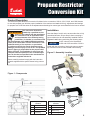
Propane Restrictor
Conversion Kit
Product Description
The Beckett Propane Restrictor Conversion Kit allows for the conversion of CG10, CG15, CG25, and CG50 burners
for use with propane gas. With the proper installation of the restrictor and attached O-ring, adjustments and settings
for propane use will be the same as the adjustments and settings for natural gas use as detailed in the burner manual.
This conversion kit shall be
installed by a qualified service
agency in accordance with the manufacturer’s instructions and all applicable codes
and requirements of the authority having
jurisdiction. (In Canada, in accordance with
the requirements of the CAN/CGA-B149 Installation
Code.) If the information in these instructions is not
followed exactly, a fire, explosion, or production
of carbon monoxide may result causing property
damage, personal injury or loss of life. The qualified
service agency is responsible for the proper installation of this kit. The installation is not proper and
complete until the operation of the converted appliance is checked, as specified in the manufacturer’s
instructions supplied with the kit.
WARNING
Installation
Note that Steps 1 and 2 on the reverse side refer to fully
assembled burners. Skip to Step 3 when converting a
burner without the air tube assembly installed. Refer to
Figures 1 and 2 when performing the following steps.
CG15 is shown in the illustrations.
CG25 and CG50 are similar. CG10 is
similar with the exception of having the gas gun assembly mounted into the air tube instead of the housing.
NOTICE
Figure 2 - Assembly Location
Please carefully read and comply with the instruction
manual supplied with the specific burner being converted.
Figure 1 - Components
Major Component Key for All
Illustrations
Major Component Key for All
Illustrations
A
Air Tube
E
External Gas Manifold
B
Jacking Screw
F
Propane Restrictor
C
Internal Gas Tube
G
Restrictor O-ring
D
Burner Housing
H
Gas Tube O-ring
1
Use authorized replacement parts
only. Restrictors are precision-machined parts and O-rings are rated for fuel contact. Do
not attempt to replicate or modify any parts. Refer to
Table 1.
The gun assembly is secured inside
NOTICE
the air tube by a spring-loaded jacking
screw. It is spring loaded in order to control the force it
can impose on the gun assembly. When installing the
jacking screw look inside the air tube to verify that the
pointed tip of the jacking screw pin is seated into the
small slot on the locating pad on top of the gun. There is
also an external verification of correct assembly: when
the screw is fully tightened, the e-clip on the top of the
center pin should come flush with the top of the screw.
Refer to Figure 3.
NOTICE
1. Remove the jacking screw (B) from the housing to
free the internal gas tube (C).
Figure 3 - Gas Gun Installation
Table 1 - Replacement Part Numbers
Burner Model
Restrictor
Part Number
Restrictor
Inside Diameter
O-Ring Part
Number
CG10.1
3246700U
0.401
3226409U
CG10.2
3246701U
0.432
3226409U
CG10.3, CG10.2S
3246702U
0.470
3226409U
CG10.1S
3246703U
0.418
3226409U
CG10.3S, CG10.6S
3246705U
0.510
3226409U
CG10.4S
3246706U
0.459
3226409U
CG10.5S
3246707U
0.482
3226409U
CG15.1S
3246709U
0.532
3226401U
CG15.2S
3246710U
0.576
3226401U
CG15.3S
3246711U
0.623
3226401U
CG15.4S
3246712U
0.677
3226401U
CG25.1S
3246713U
0.712
3226402U
6. Install the internal gas tube (C) back into the housing, refer to Figure 1. Fit the end of the tube into
the external gas manifold (E).
CG25.2S
3246714U
0.742
3226402U
CG25.3S
3246715U
0.796
3226402U
CG25.4S
3246716U
0.833
3226402U
7. Re-install the jacking screw (B). (Refer to the
above notice for installation details.)
CG25.5S
3246717U
0.889
3226402U
CG50.1S
3246718U
0.925
3226403U
8. Fill out and place the supplied Conversion Data
Plate adjacent to the rating plate.
CG50.2S
3246719U
0.980
3226403U
CG50.3S
3246720U
1.031
3226403U
9. Complete and attach the supplied Adjustment Data
CG50.4S
3246721U
1.103
3226403U
CG50.5S
3246722U
1.150
3226403U
2. Gently rock the internal gas tube (C) to loosen the
tube from the burner housing (D).
3. Inspect the O-rings and insure that they are properly lubricated. (A silicon O-ring lubricant is recommended, but automotive chassis or bearing grease
is an acceptable substitute.)
4. Referring to Figure 2, place the restrictor (F) with
pre-attached, pre-lubricated O-ring (G) into the
internal gas tube (C). Use your hand to press the
restrictor into the tube. The O-ring will hold the
restrictor in place.
5. Insure that the O-ring (H), attached to the outside
diameter of internal gas tube, is properly lubricated
and seated against the flange on the internal gas
tube.
With the gas restrictor installed, as
NOTICE
shown in Figures 1 & 2, all burner air
adjustments and gas manifold pressure adjustments for
propane will be approximately the same as the natural
gas adjustments shown in the burner manual, or printed
on the “Mfr’s Settings” label on the burner housing. For
a copy of the current burner manual go to http://www.
beckettcorp.com/protect/tech.asp. If furtherTechnical
assistance is required, call 800-645-2876, Monday thru
Friday, 8AM to 5PM EST.
Printed in USA: R.W. Beckett Corporation, P.O. Box 1289 ● Elyria, OH 44036
Canada: R.W. Beckett Canada, Ltd. ● Unit #3, 430 Laird Road ● Guelph, Ontario N1G 3X7
2
Form No. 61708 R01, 08/08