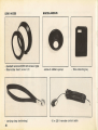
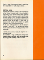
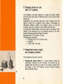
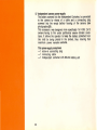
1
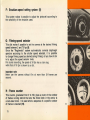
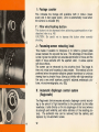
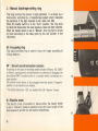
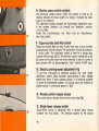
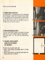
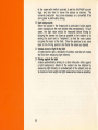
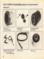
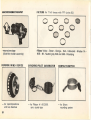
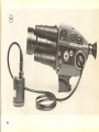
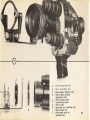
j
summary
B C 0 E F G H I -
A
I
I'
PRELIMINARY
Battery...
.. ..
Battery charging
DESCRIPTIONS:
. . .. . . .. . .
page
.
socket
8
'
'
Master switch.
..................................................
Three-position
power-supply
switch
Release button and cable-release
Emulsion-speed
Filming-speed
socket.
10
..........................
10
:.
' 11
..........................................
11
. . . . . . . . . . . . . . . . . . . . ..... . . . . . . . . . . . . . . . . . . . . . . . . . . .
11
selector.
Footage counter.
'
. .. .. .. ... ...•..... ... . ...... ..... ... .... .. ... ..
I' - Film wind locking button
K
-
Automatic
L
-
Manual diaphragm-setting
M
-
Focussing
J
3
Focussing-screen
8
:.....
setting system
Frame counter
8
12
retracting
diaphragm
knob
control
_. . . . . . . . . . . . . . . . . . . . . . . . .
system (Reglomatic
socket.
12
" .....
13
~. . . . . . . . . . . . . . . . . . . . . . . . . . . . . . . . . . . .
13
'
- Beaulieu
Patent).
12
..
ring
ring
M' - Sound synchronization
12
; . . . . . .. . . . .
13
page
N - Electric zoom. . . . . . . . . . . . . . . . . . . . . . . . . . . . . . . . . . . . . . . . . . . . . . . . . ...
13
o -
Electric zoom control contacts . . . . . . . . . . . . . . . . . . . . . . . . . . . . . . . . . . .
14
P - Tape-recorder start/stop socket. . . . . . . . . . . . . . . . . . . . . . . . . . . . . . . . . . . .
14
Electric zooming-speed adjustment ring. . . . . . . . . . . . . . . . . . . . . . . . . . . .
14
R - Remote control socket . . . . . . . . . . . . . . . . . . . . . . . . . . . . . . . . . . . . . . . . . . .
14
S - Single-frame release socket. . . . . . . . . . . . . . . . . . . . . . . . . . . . . . . . . .. . . .
14
T - Variable shutter control
15
Q -
lever
U - Macrocinematography control
5
~. . . . . . . . . . . . . . . . .
,
,................
15
V - Automatic maximum-aperture setting ring and telephoto lens
adjustment. . . . . . . . . . . . . . . . . . . . . . . . . . . . . . . . . . . . . . . . . . . . . . . . . . . . . .
15
W - Viewfinder......................................................
16
x -
16
Viewfinder eyepiece focussing ring
Y - Artificial light filter-slide slot. . . . . . . . . . . . . . . . . . . . . . . . . . . . . . . . . . . . . .
16
Z - Wrist-strap screw socket. . . . . . . . . . . . . . . . . . . . . . . . . . . . . . . . . . . . . . . . .
16
BEFORE FILMING
1.
2.
3.
4.
5.
6.
7.
8.
9.
10.
11.
Battery charge check
Loading the camera
;....
Holding the camera
.......................................
Adjusting the viewfinder eyepiece
:... .......
Setting filming speeds
Setting emulsion speed-values
Use of the automatic diaphragm
Manual use of the diaphragm
'.' . . . . . . . . . .
Framing and focussing
:..............
Use of the electric zoom
,...............
Unloading the camera
.......
SPECIAL
1.
2.
. 3.
'. 4.
6
page
17
17
17
19
19
21
21
22
23
23
24
USES.
Macrocinernatoqraphy
:
:.
Microcinematography
Single-frame filming
:...............
...
Use of the variable shutter . . . . . . . . . . . . . . . . . . . . . . . . . . . . . . . . . . . . . . . .
25
26
27
28
5. Use of remote control systems
a) Line control
b) Radio control
6. Filming in artificial light
7. Use of non-automatic lenses
8. Use of the photocell for high-contrast
LIST OF ACCESSORIES
"
scenes and subjects;
"
.
28
.
.
.
29
30
31
" 33, 34, 35, 36
USE OF THE ACCESSORIES
1.
2.
3.
4.
Battery charger for use on "the wall-socket mains (AC) .. . . . . . . . . . . . . . .
Charging device for use with 12 V batteries .... "
". ". . . . . . . . . . . . . .
Independent power-supply and charging container
:.:.
Macro-Stage
"............................................
5. Reverse wind device
Haw to. achieve superimposition
Haw to. achieve lap-dissolves
: Maintenance
: Electrical
specifications..
: A few useful hints
I,
7
37
40
40
45
". . . . . . . . . . . . .
;...........................
48
49
50
:"
"
:. .
..........................................
".....
52
53
53 "
To be sure of getting the best results from your Beaulieu camera,
it is recommended that you should be perfectly familiar with its
specifications and the possibilities of each of its component systems.
This is why we suggest that you should first get to know the camera
4008ZM2.
PRELIMINARY
A:
DESCRIPTIONS
Batteries
The camera is powered by a nickel cadmium battery
The superiority of nickel-cadmium
batteries lies chiefly in their delivering a
constant e.m.f. with little or no maintenance, and in an extraordinarily long service life.
Fully charged, they will power the camera
for:
- about 7 to 10 films at 18 fps between 10° and 50°C (500 and
122 °F)(1) ;
about two films at 18 fps at -10°C
(14 OF).
2
B: Battery charging socket
This socket is intended to accept the plug of the charger supplied
with the camera, or that of the special DC charging unit, when the
batteries periodically have to be charged (2).
C: Master Switch
This has three positions: "Auto", "Manuel", and "Test".
positions correspond to the following uses (3).
These three
"Auto" .
3
Position to be used if the camera is fitted with the basic Beaulieu
Reglomatic lens (automatic diaphragm).
In this case, leave the
switch in this position almost always.
8
"Manuel"
To be used when it is desired to uncouple the automatic
diaphragm control (Reglomatic).
Most useful when a scene has zones
of too sharply contrasted lighting which might have an unfavourable
influence on the cell's reactions and thus vitiate the exposure of the
subject to be filmed (carefully read the hints on page 31).
"Test"
This position
is used in checking
D : Three-position
This power
positions:
A
switch
battery
charge.
A ~
power supply switch
controls
the
use of the
camera:
it has three
Normal position
The switch plunger is free; at the moment of filming, it must be
depressed with the palm of the hand, thus establishing electric
contact. Then, on pressing the release button, the camera starts
filming (switch set to "Auto" or "Manuel").
To stop, first lift
the finger from the push-button release; then relax the pressure
exerted on the ·plunger: this breaks the electric circuit.
Note.- In no case must the camera's action be stopped by first
releasing the plunger, or the electric circuit will be' broken no
matter what the shutter's position.
On the contrary, by first
releasing the push-button
release, the camera stops with the
shutter closed, thus avoiding any risk of fogging.
The plunger
can then be released.
9
_
B _---~-----....,
c,...-
=--
_
_,.-,-_=-.."..-........,7
B
Safety-catch position
Useful during travel or when the camera is carried in the hand.
The plunger being in position (A), pull it out slightly (without
reaching the red dot) until the metal pin appears: press on the
broad end of the pin, thus locking the plunger in the "off" position. To release, press on the smaller end of the pin.
C
Continuous action position (exceptional)
For remote-control filming - by cable or radio - or for filming
oneself. Pull the plunger out until the red dot appears. Permanent electric contact is established. Lock the push-button
release, and control the camera's action either by radio or by
means of the cable switch.
Whim a tripod is used for filming in position (C) without a remotecontrol device, starting and stopping must be controlled with
the push-button release, either manually or with a .cable release.
E : Release button
(and cable-release
socket)
This has three positions: (7)
- "Free": the film does not move.
* "Depressed": this position puts the film in ·motion.
* "Depressed and turned gOO clockwise": this position
locks the release button and allows continuous filming.
The female thread in the center of the button receives the cable
release.
* Providing the power-supply switch (D) is in position (A) or (C).
10
F: Emulsion-speed
setting system (8)
This system makes it possible to adjust the photocell according to
the sensitivity of the emulsion used.
G: Filming-speed
selector
This dial makes it possible to set the camera at the desired filming
speed between 2 and 70 fps (9).
Since the "Reglomatic" system automatically corrects diaphragm
aperture according to the shutter speed selected, it is possible
to change filming speed as desired during filming: all you have to do
is to adjust the speed selector knob.
For sound recording, the speed of 24 fps has a click stop,
while that of 18 fps is shown by a dot.
Important nole
Never use the camera without film at more than 24 frames per
second.
9
10
H: Frame counter
This counter, graduated from 0 to 100, gives a count of the number
of frames running behind the lens; the milled knob in the center Is
a zero-reset knob. It is used when a sequence of a specific number
of frames is desired (10).
11
11
I : Footage counter
This indicates the footage still available, both in meters (lower
scale) and in feet (upper scale). Zero is automatically re-set when
the camera is unloaded (11).
I' : Film wind locking button
This button is to be depressedwhen achieving superimposition or lapdissolves (refer to p. 48)
CAUTION : Be careful not to depress this button when normally
shooting.
J : Focussing-screen
retracting
knob
This makes it possible to interpose or to retract a ground glass
screen between the eye and the lens. The advantage of the screen
is that it gives the operator an accurate appreciation of focus and the
depth or lOCUS available with the aperture used. It allows special
soft-focus effects.
The screen can be retracted by the actuating knob The image is
then only virtual and focussing is less precise. This method is to be
preferred when the operator attaches greater importance to luminous
viewing than to pinpoint focus (filming at infinity with high-sensitivity
film and a very small aperture, poorly-lit subjects, endoscopic pictures, microcinematography, etc. (12).
K: Automatic diaphragm
(Reglomatlc)
control system
The Reglomatic device ensures automatic diaphragm control according to the amount of light transmitted to the photocell by the reflex
viewfinder; it acts directly on the iris diaphragm of the lens (whence
its strength and reliability, and better definition of the resulting picture). The automatic lens can be removed from the camera, and
replaced by non-automatic lenses.
12
L: Manual diaphragm-setting
ring
This ring controls the amount of light admitted.
It is driven by a
micro-motor
controlled
by a transistorized
system which interprets
the variations in the light received by the reflex cell. (13).
When the master switch is in the "Auto" position, this ring turns
by itself and stops when the ideal exposure value has been reached.
When the master switch is set to "Manuel", this ring has to be set
by hand according
to the data given by the cell (pointer in the
viewfinder).
15 ••
M : Focussing ring
This hand-controlled
filming distance.
ring is used to focus
the image
according
to
M' : Sound synchronization socket:
According to the type of recording system chosen (Piloton, AS. 2000*
or Erlson), soundpicture
synchronization
is achieved by plugging into
this socket (14) a synchro-pilot
or a contact switch connected to a
tape recorder.
The reverse wind device is also plugged into this socket, if 'superimposition or lap-dissolves are desired.
* Val-d'Oise Electronic, 120, rue Gabriel-Peri,
16 •...••.•...••
......;
95 - Bezons - France
N : Electric zoom
This electric zoom (convertible to manual when the master switch
is set to "Manuel") makes it possible to vary the focal length of the
lens between 6 and 66 mm with perfect smoothness.
17
13
o : Electric
18
zoom control contacts
The left-hand
contact button (when the camera is held up for
viewing) shortens the focal length (i.e. brings it towards the wideangle, 6 mm position).
The right-hand contact operates the fopal-lenqth adjustment motor
in the reverse direction
(i.e. towards the "telephoto"
position
- 66 mm (15).
These
two
micro-switches
are
fitted
with
an instantaneous
start stop system.
P : Tape-recorder
start/stop socket
These two sockets (16) are used to start and stop a tape recorder
simultaneously with the camera. The connection is made by means of
a control cable. The right-hand socket is used for a classic tape
recorder (Philips type 220 S). The left-hand socket marked with a red
dot (once the socket cover has been removed) is used to control a
tape recorder with an electromagnetic
"stop" system (UHER type).
Q : Electric zooming-speed
19
adjustment ring
To go from wide-angle to telephoto
position, the focal length
adjustment
system takes between approximately
2 sees. (fastest
speed) and about 12 sees. (slowest speed). It is moreover possible
to obtain all intermediate speeds; the arrows show the direction of
greater speed (+) and slower speed (-) (17).
R : Remote control release socket
This socket takes a special remote-control-lead
S : Single-frame
plug (18).
release socket
Single-frame
filming is performed with a flexible cable
screwed into this socket.
The pressure applied to the
14
release
release
should
be as brief as possible
(19).
T : Variable shutter control lever
The variable shutter is a mechanical
device which independently
from the diaphragm,
modifies the film exposure time as desired.
It is thus possible to go from maximum aperture to complete blackout, permitting
fade-ins and fade-outs,
superimpositions
and lapdissolves. Shutter aperture variations are controlled by means of a
lever (20) whose use is depicted on page 28.
U : Macrocinematography
21
control
The "macro': control makes it possible to film subjects at very close
ranges from 0 mm (1/25", transparent subjects or transparencies)
to 1,50 m (just under 5 ft.).
This control
also allows soft-focus
fades (21).
22
V: Automatic maximum-aperture
setting ring and telephoto
lens adjustment
This button
position
aperture
position
matically
15
has a two position switch:
(22)
1 iJi.9ht pressure): the diaphragm
of 1,8;
2 (heavy pressure): the focal-length
sets the lens to "telephoto".
opens
to
Its widest
varying system auto23~
••••••
Lt· .••••••••
~
~
W: Viewfinder
24
The Beaulieu has the largest viewfinder screen, The pointer in the
viewfinder makes it possible to check exposure. In order to film
under good conditions, it must remain within the notch to the
right.
At the bottom of the viewing window, another notch check on film
running (23).
When the film-running indicator ceases to flicker, this means that the
film cartridge loaded has been completely exposed; it should then
be replaced by a fresh cartridge.
X: Viewfinder
25
•
~ ~~~~
focussing ring
The viewfinder can be adjusted to the operator's eyesight by means
of the eyepiece focussing ring. Once this adjustment has been
made, the ring can be locked by means of the locking screw (24).
Y: Artificial
®
eyepiece
light filter-slide
slot
The slot in the pistol grip takes a flat key for filming in artificial
light (25) .See paragraph artificial light, page 29 .
Z: Wrist-strap
Z
screw socket
This is used to fit the wrist strap to the camera's pistol grip. (Z)
16
BEFORE FILMING
1 Battery-Charge check
0
Set the master-switch to "Test".
Press the three-position power
switch in and look at the pointer in the viewfinder. For an accurate
check, wait for 20 seconds. The pointer should settle above the
index notch (should it not do so charge the battery; see page 37).
Then return the master switch to its original position. This check
should be carried out periodically (26).
:zo
Loading the camera
Open the camera side door and slip in the film cartridge with its
notches towards the front: Close the door. The reference of the
type of emulsion loaded should be visible through the window.
Press the release button for two seconds to check that the film
is running through properly: .the running indicator should move
vertically in the lower notch of the viewfinder. If not, repeat the
loading operation (27).
Important
A \Wratten filter allowing dayllqht use of indoor color films is built
into the camera. According to the type of film loaded, this filter
will be either [interposed or retracted thanks to the notches on the
film cartridges. If artificial lighting is to be used (lamps, floodlights, etc.), see the paragraph on Filming in artificial light
26
27
•••••••••••
3 Holding the camera
0
When the camera is hand-held, the three-position power supply
switch is depressed by the heel of the hand. This means that the
camera is powered. In order to film, it is. therefore only necessary
to hold the pistol grip and to squeeze the release button (the master
swifch being in the "Auto" or "Manuel" position) (28).
17
~!!!!!::~!!
C
28
The pistol grip's shape is ideal, and perfectly functional for any hand,
providing the camera is held as shown in photograph 28. Grasp the
grip with the middle and ring fingers, placing them between the camera
body and the grip base, the little finger resting on the wrist-strap screw.
When filming with the camera
29
When filming at a focal length greater than 15 mm, the best way of
stabilizing the camera is to hold the upper part with the free hand. It
is recommended, when working without a tripod, to place the camera
itself on anything that may serve as a supporting base, or to weigh
the full weight of the body against some fixed structure (29).
When carrying the camera at arm's length
Screw the wrist-strap tight into its socket with a coin. Slip your wrist
through the strap loop as shown in photograph 30. The camera is thus
maintained by your middle finger. The base-plate projecting from the
grip acts as a hook-support,
and allows you· to carry the camera
without fatigue. (30)
lmportant
30
Let us again stress that never must the camera be stopped by
releasing the power switch first, for in this case the power circuit
is cut and the shutter may stop in any position, which may lead to
fogging
On the contrary, if the release button is freed first, the
camera will stop with shutter closed, thus obviating any risk of a
white frame The power switch should only be released later.
This power-supply switch also acts as a safety device. In the "rest"
position, the power supply circuit is interrupted.
18
4° Adjusting the vlewflnder
eyepiece
The zoom being in the wide-angle position (6 mm in the case of
the standard lens), and the focussing ring set to infinity open the
diaphragm to maximum aperture and put the ground glass screen
in place by means of the knob. Aim at an object over 150 ft distant
and rotate the eyepiece ring until the sublect is perfectly sharp on
the screen.
The viewfinder is now adjusted once and for all An operator who
usually wears glasses can, for more comfortable viewing, remove
them and focus with the naked eye in accordance with his own
eyesight (within tolerance limits of - 2 to + 2 diopters).
The
eyepiece focussing ring can be locked by means of the screw (31).
31
5° Setting filming speeds
Bring. the speed selected on the dial opposite the mark.
The 4008ZM 2 will automatically correct diaphragm apertures;
this means you can change filming speed as you wish while
filming.
Normal filming speed is 18 fps. If this speed is decreased, an
accelerated motion will appear on projection; this becomes very
great when filming is done at 2 fps. (ninefold acceleration) (32).
If this speed is increased to between 18 and 70 fps., slow-motion
effects making it possible to break down and analyze movements
are obtained (a pole-vaulter, for example).
The speed of two fps.
- allows filming under very poor lighting conditions (church interiors) without addition of artificial lighting, since the exposure
time at this speed is very long: 1/7 second;
- makes It possible to analyze very slow movements. Example:
a watch filmed at two fps will, on projecting the film, give a quite
extraordinary effect, the seconds hand completing a revolution
19
32
(I.e. one minute) in just over six seconds.
If projection
is
continued for one minute, the minutes hand will move through
nine minutes on the watch dial.
In order to'
at seeds
slower than ei ht f
the camera has to
be put" on a tripod, an ~an.l.!5Z.C..position
on the master switci"),
has to be used.:.
DO NOT FORGET: Never use t@ camera
24 frames/sec.
DURING
TABLE OF EXPOSURE TIMES
NORMAL FILMING AT VARIOUS
2
4
8
18
25
36
50
70
33
20
without
f.p.s.
f.p.s.
f.p.s.
f.p.s.
f.p.s.
f.p.s.
f.p.s.
f.p.s.
1/7
1/15
1/30
1/65
1/87
1/130
1/175
1/250
second
second
second
second
second
second
second
second
film at more than
SPEEDS
If filming with the shutter half open, divide exposure times by 2.
(E.g.: 18 f.p.s. = 1/130 second. For single-frame filming, see page 27).
6° Setting emulsion-speed
values
Green dot: set against this the sensitivity of the emulsion used (3~)
(black-and-white or color film).
Caution: For outdoor filming with "indoor" type film, the "daylight
speed" should be set opposite the green dot.
Example: For Kodachrome " type A film, set 25 ASA for outdoor
filming (daylight).
A correction of this calibration can be effected in the proportion
of plus or minus 1/2 or 1 diaphragm number.
- In order to overexpose, set a film speed tending towards the
white dots.
- The first white dot gives you an overexposure of 1/2 diaphragm
value (34):
- The second white dot gives an overexposure of 1 full diaphragm
value (34).
- In order to underexpose, set a film speed tending towards thered dots:
- The first red dot gives an underexposure of 1/2 diaphragm
value (35).
- The second red dot gives an underexposure of 1 full diaphragm
value (35).
-r
Use of the automatic
diaphragm
- Set the master switch to "Auto".
- Take the camera in hand and depress the power-supply switch.
According to the amount of light received, the galvanometer pointer
will move in the viewfinder, giving a check of automatic operation
21
34
35
P08ltlon of the pointer needle:
- Within the notch: exposure satisfactery.
- Above the notch: risk ot everexpesure ..
- Belew the notch: risk of underexposure,
Important
In all cases, the viewfinder needle should lie within the notch,
If it does net, two. possible reasons exist:
- either too .rnuch light: film with the shutter halt-ctosed, not forgetting to. divide by 2 the film sensitivity value set en the filmspeed dial;
- er net eneugh light: cheese a faster emulsion or, i"f the subject
permits, work at a sfower filming speed.
Fer remote-control filming, you must:
- set the camera en a tripod;
- lock the power supply switch In the continuous posltlcn "C" ;
- set the release button to. the "continuous" posltlon and use one
ot the remote-control devices;
,
-' if master switch is set to auto tor automatic, exposure control, the
ocular should be masked with a special viewfinder cap (available
as an accessory).
8 Manual use of the diaphragm
0
After setting the master-swltch to "Manuel", sight the subject to. be
filmed, and bring the pointer needle In the viewfinder opposite
the mark by rotating the diaphragm setting ring. The Beaulieu Is
ready to. film.
If lighting conditiens on the subject vary, rotate the ring to. keep the
needle within the notch.
In order to. disconnect the automatic action ot the Reglematic, just
set the master switch to "Manuel" and proceed as for non-automatic
22
"
lenses (see below). The Beaulieu's reflex cell, which lies behind
the lens, 9.ivesaccurate data no matter what the optical equipment: it
is thus possible,' with' 4008 ZM 2 cameras, to use any standard
"C"-mount cine lenses, most still miniature camera lenses, and all
filters.
Correction is automatic.
go Framing and focussing
The viewfinder eyepiece being once and for all adjusted to the operator's eyesight. the subject should be sharp on the screen, for the
image viewed is that which will be filmed. To achieve thts, all. that
need"be done is to rotate the lens focussing ring until the Image on
the screen is in perfect focus. It is necessary that this adjustment
be made atrnaxlmum aperture and with the focal-length adjustment
in the "telephoto" position with the 4008ZM 2. in order to obtain both
these positions simultaneously, just depress button V to maximum
depth.
Once this adjustment has been made, any focal lengths (set by electric or manual control) can be used without having to adjust the
focus.
10" Use of the electric zoom.
The focal length adjustment device (zoom) on the Beaulieu 4008ZM2
is electrically actuated. Passage from wide-angle position to telephoto posltlon, and vice versa, is simply effected by pressing on
switch 0 or switeh O' (36).
Switch 0 drives the lens towards the telephoto' position.
23
36
Switch 0' drives it towards the wide-angle position.
The time for extreme changes in focal lengths is from about 2 secs.
to about 12 secs.
The adjustment ring Q merely has to be set accordingly.
11 Unloading the camera
0
In Beaulieu cameras, the end of the film is shown by the cessation
of the flicker-indicator in the lower part of the viewfinder. Open
the side door and take out the cartridge. The word "exposed"
should appear on the film itself; this is a certain identification of an
exposed film, and avoids re-Ioading the camera with an alreadyexposed film.
CAUTION. - When removing a partly-exposed cartridge, 7 frames are
fogged and the footage counter automatically returns to 15 m/50 ft.
If it is imperative that cartridges should be changed the length
of unexposed film still available should be noted on the label in
such a position that it can be read through the side-door window
when the film comes to be loaded once more.
This figure will allow the operator to correct the footage counter's
indications and to be certain of the amount of film stili unexposed.
IMPORTANT.
- After filming, make quite certain the power-supply
switch is in position A (normal). Never leave this switch in position C
when not in use: you would run the risk of completely discharging
the battery. This switch should permanently be kept in positions A
or B both of which automatically interrupt the battery power
circuit.
24
SPECIAL
USES
1° Macroclnematography
Without the special "Macro" system, you can film as close as
three feet from .any object.
But, closer than this, the new Macrocinematographic system of the
4008ZM2avoids the use of special lenses and extension tubes.
It makes it possible to film from distances of. 0 mm (transparent
slides, phototransparencles, etc.\ up to 1,50 m (in other words,
from 0.inch to five feet).
Operations to be performed before "macro" focussing:
- Fit the camera on its tripod .
.- Make certain the ground glass screen is positioned.
- Free the "Macro" slide by pressing on its end (37), and bring it
into low position in order to reach the greatest magnification
ratios (38).
- Set the zoom to "low speed".
- Set the master switch to "Manuel", so as to be able to open the
diaphragm to full aperture, by hand.
Note. - The position of the distance ring has only a very slight effect
on macro focussing (preferably set it at infinity).
According to the subject to be filmed, focussing is performed by
using:
- either the electric zoom switches;
- or the "macro" knob itself (more particularly when seeking
smaller magnification ratios);
- or by moving the camera towards or away from the subject.
25
The "Macro" slide being In Its "low" position, nere are a few
"Macro" positions between o and 1,50 m
( 0 to 59 Inches).
Distance
from surface
of lens
to subject
o mm
4 mm
10 mm
30
60
100
120
mm
mm
mm
mm
Subject
dimensions
(mm)
position of
focalleng th
ring
position of
focusing
ring
Lighting
23.5 x 17.7
23,5x17.7
25 x 18.8
M*
M*
M*
to infinity
to infinity
to infinity
Transparency
Transparency
Transparency
or Normal
to
to
to
to
Normal
Normal
Normal
Normal
27 x
29 x
31.5 x
33 x
* M : "Macro-Maxi"
length ring
20.3
21.8
23.7
24.8
44mm
48 mm
49 mm
50 mm
infinity
infinity
infinity
infinity
position, located by red markings on the focal
IMPORTANT. - After filming "Macro" sequences, do not forget
to return the "Macro" slide to Its initial position.
Note. - It Is also possible to obtain soft-focus fade-Ins or fade-outs
by lowering or raising the "Macro" slide while 'filming.
2" Mlcroclnemotagraphy
For microcinematographic uses, Beaulieu has designed a special
set of connecting rings and extenslon tubes to be used according to
the magnification ratios desired. The camera, once Its normal lens
26
<,
1
has been removed, Is directly fitted to the microscope eyepiece by
means of these connecting rings and extension tubes. For preference, focussing ·is done on a virtual Image. For this type of
work. the built-in photocell proves a tremendous advantage for, as
in all other cases, all that has to be done Is to bring the viewfinder
needle opposite its mark by acting, on the one hand, on filming
speed and, on the other, on the microscope's light source.
3° Single-frame
filming
Frame-by-frame filming Is essential if one wishes to shoot animated
cartoon or puppet scenes, and also to record slow-development
phenomena. This type of filming cannot be .effected otherwise than
on a tripod, in "Manuel" position, using a flexible cable release
(power switch In the continuous position "O") (39).
'Under these conditions, frame-exposure
2 fps
1/7 sec.
4 fps
1/15 sec.
8 fps = 1/30 sec.
18 fps
1/65 sec.
=
=
=
times are a follows:
25 fps
1/87 sec.
36 fps
1/87 sec.
50 fps = 1/87 sec.
70 fps
1/87 sec.
=
=
=
(with the shutter half-open: divide the above exposure times by
two: example: 1/130 sec. at 18 fps).
Caution. - Never lock the flexible cable release In the "continuous"
position for single-frame filming.
Pressure time on the cable
release should be as short as poestble.,
27
39
4° Use of the variable
40
shutter
The variable shutter is controlled
by means of the lever located
on top of the camera body.
It works from rear to front to close
the shutter slot (40), and from front to rear to open it.
'It can be locked in the half-closed position (41) (i.e. allowing half the
normal light through). orin the fully closed position at the extreme
front end of the slot (42) (i.e. the shutter is completed closed). In
both cases, the lever is pulled upwards to lock the variable shutter.
Fades make it possible to finish a scene or a shot by gradually
darkening the pictures until complete darkness is reached, or, on the
contrary, to start a scene in complete darkness and gradually to
lighten until a normal lighting intensity is reached.
It is generally
preferable that fades should be filmed with the camera on a tripod,
so that no attention has to be paid to framing and the lever can be
very regularly actuated in the desired time, according to the effect
required (average time: 4 secs., or 72 frames under normal filming
conditions).
5° Use of remote control
41
This particular facility offered by the Beaulieu cinecamera will be
appreciated by all those making films calling for very discrete operation (wildlife scenes, children at play, etc.) or having a marked element of danger (wild animals, car races, scientific experiments, etc.).
There are two possible control methods: line, or radio transmitter.
LINE CONTROL
42
Any two-strand
line can do the job providing it is fitted with
switch and an appropriate jack plug.
.
a) Plug the lead connection into the jack "R" (43).
b) Lock the release button in the "continuous"
position.
c) Put power switch in position 3.
d) Control the camera's operation by means of the switch.
28
a
Maximum length of connecting lead: 200 meters (approx. 660 ft.).
In order to avoid any extraneous light, it is recommended that the
viewfinder eyepiece should be covered.
RADIO
CONTROL
Any type of single-channel receiving-transmitting radio-control systems can be used. (A single channel is enough.)
a) Plug the male receiver plug into the camera jack.
b) Lock the release in the "continuous" filming position.
c) Put power switch in position c.
d) Control the camera's operation from the transmitter station.
In this case also, it is recommended that the viewfinder eyepiece
should be kept covered. Maximum operating distance depends on
the power of the radio sets used. We strongly advise test runs
before attempting filming.
43
NOTE. - When under cable or radio control, the camera
may stop with its shutter open or closed; or again in an intermediate position. The Reglomatic system goes on operating but, if the
shutter is not completely shut when the camera is at a standstill, the
diaphragm will only assume a correct position after a certain time
once filming is resumed; this will lead to variable exposures in the
initial frames of the sequence.
IMPORTANT
6° Filming in artificial light
1. Slip the key into the slot in the camera pistol grip so as to cut
out the filter (44) ;
~
2. Set, opposite the green dot, the "artificial light" speed of film
used.
Example: Type A Kodachrome II film: set the speed of 40 ASA if you
wish to film indoors with "artificial light" type lighting. .
Note: When using "daylight" type artificial lighting, use as you would
outdoors:
29
44
a) The flIter retraction slide should be removed from its slot;
b) The "daylight" speed of the film should be set opposite the
green dot.
Example: A-type Kodachrome II film: set 25 ASA when you want to
film In "daylight" type artltlclal light.
45
46
7" Use of non-automatic lenses
1. Standard the 16 mm lenses "C" mount lenses
Over and above the lenses especially designed for the Super 8
format, the 4008 ZM 2 camera will accept any object lens designed for 16-mm work (C mount: extension 17.52 mm (11/16"),thread 25.4 mm (1") - max. thread length 3.8 mm (.15"). (45)
2. Stili-camera lenses
Most interchangeable 24 X 36 miniature camera lenses can be fitted
to the Beaulieu 4008 ZM 2 by means of intermediate adapter rings.
See your Beaulieu dealer about this point.
Fitting or removing the automatic lens
- Unscrew the release button
- Holding the camera vertically, lens down, unscrew the lens. (46)
Caution: do not hold it only by means of the Reglomatic device,
but grasp the lens as far back as possible.
- To replace the lens, screw it back into place under the same
conditions, then replace the release button. When replacing this
button, care should be taken not to damage the screw-thread.
- Screw in the lens, without exerting too much force.
Connections between the battery and. the camera film-speed-setting
system are made by means of three studs and contacts situated, on
the one hand, around the rear screw-thread of the lens and, on the
other, on the camera body itself. These contacts must be kept
absolutely clean at all times and, in particular, free from oxides.
The camera-lens screw-thread connections are standard: if the lens
Is screwed in properly, a correct inter-contact position should result.
30
f
To check proper contact, press on the power switch, and see
whether the automatic diaphragm is functioning as it should. Should
this not be the case, adjust the lens in its C-mount so that proper
contact is made.
Note: When using these non-automatic lenses, take into account
the advice given in the paragraph entitled "Manual use of Lenses",
page 22.
Caution: When you change lenses (as when camera maintenance is
involved, see page.52 l, never put any object into the film gate. A
very thin gelatin filter lies just behind it. Should it come to be
damaged, the camera would become unserviceable and would have
to be completely dismantled for repair.
8° Use of the photocell
for high-contrast scenes or subjects
II
The cell, on which the light rays coming through the lens impinge,
is activated by the integrated luminosity of the scene in the lens
field. In certain cases of very sharply contrasted scenes, the human
eye will interpret these contrasts of Itself; such is unfortunately not
the case with a cell, whence the need for precautions if certain
areas of the field are not to be over or underexposed, errors which
may seem impardonable to experienced amateurs. These corrections
must be applied with the Reglomatic system disconnected if the
camera is so fitted. Set the master switch to "Manuel" and adjust
the aperture by hand.
AI
Wide, luminous-sky
backgrounds
- Snow scenes
When the sky occupies an important part of the field covered by
the lens and the foreground remains In relative shadow, the
sky's brilliance will affect the cell's reactions to the point of
provoking general underexposure. In such a case, one should
take the precaution of aiming at a slightly lower point or at part
31
of the scene with medium contrast, to set the diaphragm accordingly, and only then to frame the picture as desired. The
converse precaution may prove necessary on a snowfield if the
sun's glare is particularly strong.
B/ Dark backgrounds
When the subject in the foreground is particularly bright against
a dark background, the main subject risks overexposure. In such
cases, the light value should be measured before filming by
bringing the camera as close as possible to the subject or by
setting the 'zoom lens to "telephoto", so that the main subject
occupies the major of the field. Once the aperture is set, come
back to the filming position and frame the scene as desired.
C/ Intense source of light In the field
A bright electric light, a brilliantly-lit window, must be left outside
the field when measuring light intensity.
0/ Filming agaInst the light
Unless systematically aiming at a dark silhouette effect agains1
a light background, details of the subject can be obtained by
measuring light intensity on a shaded part of the subject (lens set
to maximum focal length and light measured as close as possible).
32
I
\
)
I
LIST OF SUPER 8 ACCESSORIES adaptable to the Beaulieu 4008 ZM 2
POWER SUPPLY
- 250 mA, 7.2 V
accumulator battery
- standard 30 mA,
7.2 V charger
- independent charging
box container
- connecting cord for charging
from a 12-V car battery
(with crocodile clips)
- connecting
- contact
33
cord
plug
MACROCINEMATOGRAPHY
FI LTERS
for 11 x 6 lenses with
o o
PFF(series
8,5)
0
o o
0
o
o
- macrocine
(Slide/title
REVERSE
-
34
stage
holder assembly)
WIND
DEVICE
for superimpositions
and lap dissolves
- Filters Yellow - Green - Orange - Red - Ultraviolet
80 B - 85 - Neutral grey 0.30 and 0.60 ~ Polarizing
SVNCHRO-PILOT
-
GENERATOR
forPiloton
or AS 2000.
sync sound-type
CONTACT-SWITCH
-
for Erlson
recording system
- Wratten 1A _
PORTRAIT-LENSES
'for 11 x6
lenses with
~ABLERELEASES
PFF (series 8,5)
000
- 50 em (20·") straight
- 24 em (9 Yo")
"
- 30 em (12") curved
- Portrait lenses 1 d - 2 d - 4 d
EXTENSION
LENSES:
CASES
RINGS FOR PHOTO
.• • ••
• e
.,11
'
- Small-size hold-all type case,
grained leather
- Large luxury model hold-all
type case, smooth leather
35
".
.• LEICA (screw type).
LEICA (bayonet type)
• EDIXA.
ROBOT-ROYAL
• CONTAREX • PAXETTE • PRACTINA •
EXACTA • RETINA REFLEX'S.
BESSAMATIC
• LEICAFLEX • MINOLTA
• FOCA (screw type) • CANON PELLIX
• NIKON (with E2 ring).
NIKON (without E2
ring) • ICAREX • TELYT-LEITZ
LENS
HOODS
. standard lens hood (46.5 mm screw-in type
- filter-holder
hood (series 8,5)
- carrying
36
strap (wrist-strap)
MISCELLAN EOUS
. screw-in
rubber eyecup
- filter-retracting
·10 m (33 ft remotes control
cable
key
USE OF THE
ACCESSORIES
1° Battery charger for use on wall-socket mains
The battery is made up or 6 nicke -cadmium accumulator cells; they
are leakproof and soldered within a metal container which screws
directly into the camera housing's "battery" compartment. Capacity:
250 mAlhrs. This type of battery is a standard feature on all Beaulieu
cinecameras bearing serial numbers of 851.268or over. It can be
recharged from the wall socket by means of the charger unit
supplied with every camera.(47)
Procedure:
a) place the voltage control on 110 or 220 V according to supply.
b) place the power switch in position A or B.
c) connect the charger plug with the camera jack socket.
d) plug the charger into the wall socket (AC mains only).
IMPORTANT:
Be sure to carry out these operations In the right order, and more
especially to plug the charger Into the camera Jack first and only
therafter to connect to the mains.
.
The superiority of nickel- cadmium batteries essentially lies in the
fact that they deliver a constant voltage, call for little or no maintenance, and have a practically unlimited life. When fully Charged,
they will power the camera for:
-about 7 to 10 films at 18 fps between +100 and +50°C (500 122OF).
- about 2 films at 18 fps at - 10°C (14OF).
TABLE OF NORMAL CHARGING TIMES
After shooting
Charging· time required
2 films
4 hours
4 films
7 hours
6 films
9 hours
8 films
11 hours
10 films
14 hours
37
38
There is no danger of overcharging the battery in under 5 days.
After a-rest period of 1 or 2 months, charge for 20 hours.
EXCEPTIONAL
CHARGE
Immediately after the camera's purchase, or when the batteries have
not been charged for several months, it is very beneficial to
"retrain" them for normal use in the following manner: charge them
for 24 hours. Then let the camera run, empty, for about 10 minutes.
Then charge again for 12 hours. This method is preferable to using
a long consecutive charging period to put batteries left dormant and
inadequately charged back into shape. In serious cases, this
procedure can be repeated until the batteries are perfectly
"re-educated", without any risk of overcharging them.
The only reason for this procedure is to allow the batteries to
"recuperate 'a normal rhythm" if they have been long neglected.
Once this has been achieved. resume charging according to normal
charging times.
A few hints: To insure maximum battery life, charge them once a
month when not in use.
Do not hesitate to re-charge the battery after a filming session.
There Is no danger of overcharging.
Never leave batteries completely discharged, as this might finally put them out of action.
39
~ Charging device for use
with 12 V batteries
This accessory has been designed to charge the camera battery
from the mast usual types of batteries found in cars, trucks, boats,
aircraft, etc.
Consisting of two crocodile clips and a 10-ft charging cord, this
device is fitted with "a regulator which makes it unnecessary to
distinguish between positive and negative poles, so. that the
crocodile clips may be fitted to either battery terminal (49).
To charge the camera battery, the output lead is connected either
directly to the camera jack or to the special socket on the Independent Charging and Power-Supply Container.
Charging time on 12-V battery: 12 hours.
This accessory comprises:
- 1 charging cord, with crocodile clips,
-1
regulator,
-1 output lead, with plug.
3° Independent power supply
"and charging container
This accessory's function is twofold:
A Charging \he camera battery (or a spare battery) outside the
camera (48). Screwed into this container, the batteries can be
charged from the mains by means of the charger supplied with
the camera, or from 12-V batteries, using the special charging
device described above.
48
40
41
Bf Independent camera power-supply
The battery screwed into the Independent Container, is connected
to the camera by means of a cable and a connecting plug
screwed into the empty battery housing of the camera (see
photographs (SO) .
.
This accessory was designed more specifically for 4008 Z M 2
owners having to. film under particularly severe climatic condItions. It allows the operator to keep the battery protected from
the cold by being placed in his pocket, thus insuring that
maximum power remains available.
This
-1
- 1
-1
42
power"supply comprises:
screw-in connecting plug
connecting cable
Independent container with 250-mA battery unit
.t1r,::
'-,~
:11;;,
I
43
,
I \
~
':I~~IJ~". ~
,
~--------~51~--------------------------------~
A
c
B
A - Front mounting ring
B - Rear mounting ring
C
Macro-stage retaining ring
D - Macro-stage distance
adjustment slide
E - Slide locking screw
F - Decentering screw
G - Slide holder
H - Specimen box retaining ring
I - Macro-stage rest
J
Attachment point for
specimen-box
44
4° The macro-stage
(slide/title
holder assembly)
This accessory has been designed by BEAULIEU to facilitate macrocinematographic shooting at subject lens distances of between 3 and
12 cm (1.2 and 4.8 ins.) approximately. Its most common uses are
filming transparencies and slides, post-cards or insects. It can also
act as stabilizer when macro-filming without a tripod.
Fitting the macro-stage to the BEAULIEU
4008 ZM 2
- Unscrew the two mounting rings. (front and rear rings).
- Screw these two parts back together after inserting between them
the macro-stage retaining ring.
- Screw the complete assembly on to the camera (the focussing
ring preferably being set at infinity)(51)
Note: For macto-filming, the focussing ring should always be left
set at infinity.
How the macro-stage works
a) Distance-adjustment slide: the macro-staqe- being fitted to the
camera, the slide system makes it possible to move the subject
forwards or backwards so as to achieve the required magnification
ratio.
In order to set the distance, loosen the locking screw, slide the
subject back and forth until it is in the desired position, and tighten
the locking screw,
The field covered at 1.2 ins from the lens is 27 mm (1.06 in) x 20.3 mm
(0.8 in) and, at 4.8 ins, 33 mm (1.3 in) x 24.8 rnrn (0.98 in) (52)
52p45
~~-------
b) Decentering system: Horizontal decentering allows more accurate
framing of the transparency or slide to be filmed. To adjust, undo
the decentering screw and push the slide hotder to the left or to
the right; tighten the screw again when the desired framing has
been achieved. For vertical decentering, push the slide upwards
or downwards in the slide-holder grooves. (53)
53
Chief uses
a) Reproducing transparencies and slides: This is the "most common
use. Merely place the 24 x 36 mm, 24 x 24 mm, or 40 X 40 mm
slide into the macro-stage's slide holder. (54)
54
b) Filming insects, etc.:
When the object to be filmed (butterflies, moths, flies, or small
fish, etc.) is placed in the specimen-box, place the box between
its retaining ring and the slide holder (using the two retaining
screws). (55)
46
55
c)
To
-
Filming post - cards:
film a detail on a post-card:
Remove the slide holder by undoing the decentering
Slip the post-card into the slide-holder groove.
Tighten the decentering screw on the post-card. (56)
screw.
d) Macro-filming without a tripod:
The subject-distance
adjustment slide can also be used as a rest
for macrofilming
without the macro-stage
(for instance, a coin).
This resting point avoids having to use a tripod to stabilize the
camera (57)
57
47
50 Reverse wind device
58
This attachment (58) is intended to achieve superimposition and lapdissolves. It can be operated only after the film wind locking button
(I' on page 2) has been momentarily depressed.
It is to be screwed into the sync socket (M' on page 2).
It is basically made up of two concentric rings: a black knurled ring;
and black ring with bright notches.
The knurled ring is for tightening the device into the M' sound sync
socket, while the notched ring is intended to manually advance the
film in reverse. This ring is fitted with two click-stop positions:
a) engaged: when pulled away from the knurled ring
b) disengaged: when pushed against the knurled ring
Mounting
the reverse wind device:
- Set the shaft key so that it matches the slot of the sound sync shaft
- Screw in the device (clockwise)
- Engage the notched ring, and lock the device by turning the knur led ring. When not using the device, the notched ring should be
disengaged;
otherwise, battery life would be appreciably reduced.
59
Important:
Do not run more than 100 frames (e.g. 5 seconds at 18 f.p.s. ; 4 seconds at 25 f.p.s.) while depressing the film wind locking button.
Do not depress the film wind locking button when running the camera
at speeds inexcess of 25 f. p.s.
60
48
How to achieve a superimposition
To be sure of getting the best results from your Beaulieu camera,
it is recommended
that you should be perfectly familiar with its
specifications and the possibilities of each of its component systems.
This is why we suggest that you should first get to know the camera
4008ZM2.
PRELIMINARY
The purpose of the superimposition
scene to the next by superimposing
end of the preceding one. (61)
Ending a scene:
- simultaneously
DESCRIPTIONS
A: Batteries
The camera is powered by a nickel cadmium battery
The superiority of nickel-cadmium
batteries lies chiefly in their delivering
a
constant e.m.f. with little or no maintenance. and in an extraordinarily long service life.
Fully charged, they will power the camera
for:
about 7 to 10 films at 18 fps between 100 and 500C (500 and
122 °F)(1) ;
about two films at 18 fps at -10
°C (14 OF).
2
C: Master Switch
This has three positions: "Auto", "Manuel", and "Test".
positions correspond to the following uses (3).
3
-
-
B: Battery charging socket
This socket is intended to accept the plug of the charger supplied
with the camera, or that of the specialDe
charging unit, when the
batteries periodically have to be charged (2).
These three
-
(100 frame lengths, at maximum)
- lock the film wind by depressing the film wind
locking button I'
- without
interruption - set the variable shutter
lever T in half-closed position (60)
lock the lever T in half-closed position
complete the scene and stop shooting
Close the shutter by setting the lever T in the extreme forward
position and lock it
lock the three position power supply switch D in the safety catch
position (p. 10)
lock the release button E in continuous filming position (p. 10)
Engage the notched ring of the, reverse wind device
Rotate the notched ring clockwise. Finger pressure on the notched
ring must be just adequate to permit the film to run in reverse,
Rotate until fingers slip around the ring.
Free the release button E
Set the Switch D to desired position
Beginning
the next scene:
- Release the lever T, draw it back in half-closed position and lock it
- Start shooting
- Without interruption - release and draw back the lever T into the
extreme backward position after a lapse of time equal to that of
shooting the preceding scene with the lever in half-closed position
"Auto" .
Position to be used If the camera is fitted with the basic Beaulieu
Reglomatic
lens (automatic diaphragm).
In this case, leave the
switch in this position almost always.
8
effect:
is to get a transition from one
the beginning of a scene on the
49
61
62
How to achieve lap-dissolves:
Lap-dissolves are intended to blend two successive scenes by superimposing one over the other during a given lapse of time, the first
scene being gradually faded out while the next is gradually faded
in. (62) Lap-dissolves are achieved by the combined operation of the
variable shutter and reverse wind device.
Ending a scene:
(100 frame lengths, at maximum) (60)
Depress the film wind locking button I'
- Gradually push forward the variable shutter control lever T (fadeout) until it stops
Stop shooting
Lock the lever T in its extreme forward position
Lock the three position power supply switch Din the safety catch
position (p 10)
Engage the notched ring of the reverse wind device
Rotate the notched ring clockwise. Finger pressure on the notched
ring must be just adequate to permit the film to run in reverse.
Rotate until fingers slip around the ring.
Free the release buton E
Set the switch D to desired position
Beginning
the next scene:
Release the lever T, and maintain it in its extreme forward position
Start shooting
Gradually draw back the lever T to its extreme backward position
(fade-in), within a lapse of time equal to that of fading out when
completing the preceding scene.
.
50
IMPORTANT·
Be careful not to depress the film
when shooting normally.
wind
locking
button
Keep in mind to maintain the shutter in closed position
(lever T all the way forward) when running the film in reverse.
51
MAINTENANCE
Lens surfaces must be kept extremely Clean. Outside surfaces are
wiped with a fine, clean, lint-free cloth. This cloth should never be
moistened. After filming, screw in the front lens cap.
63
2" Film gate (19)
The gate should be cleaned frequently (every 3 or 4 films) with the
hand blower (63)
Caution
Never slip anything (hand blower, brush or cloth) through the gate,
as this would damage the gelatin filters. To remove any possible
specks of dust, blow carefully with the hand blower.
:r'
Reflex sys,tem
The mirror and focussing screen can be reached through the lens
mount opening. Unscrew the lens: the mirror becomes visible. If
there are dust specks on it, remove them with the hand blower.
4° Lubrication
This should always be left to us. After three years, it is advisable
to leave the camera in the care of a Beaulieu dealer, who will
overhaul it.
52
ELECTRICAL DATA
D.C. :
The camera's consumption Is obviously dependent on filming speed,
and lies between 200 and 500 milliamps. Normal power supply
voltage: 7.2 volts.
Rectified. A.C. :
Never use the camera on the mains, even with any transformer to
be found on the market, for the current must not merely be rectified,
but also carefully filtered.
53
A FEW USEFUL HINTS
Focussing
In order to achieve pinpoint focussing with the 'ground-glass screen,
it is essential to .bring the zoom lens to its ••telephoto" position
(e.g. for the standard lens : 66 mm) and to full aperture (f 1,8 for
the standardlens.). Focus the image with the focussing ring. Then
adjust the focal length to frame the picture exactly as desired: the
image will remain perfectly sharp.
Zoom
For focal lengths greater than 30 or 40 mm, the use of a tripod is
highly advisable, for otherwise the operator's slightest movements
are amplified and, on projection, the picture will oe unsteady. As
a general rule, use a tripod whenever possible: the film's steadiness
will lhvarlably.qaln by it.
Photocell
Only shoot when the needle is in the indicator notch. If the light
is too poor, use slow filming speeds (ASA compensation is built-in)
when the subject is not moving.
Some sequences may have to be filmed in zones' in which hghtcontrast is strong (beach or snow scenes', dark Shadows...). When
the film subject is in one ot these zones (full sunlight or deep
shadow), it is imperative that the cell should only react to the
actual lighting in this zone alone.
54
To achieve this, "zoom" to maximum focal length on the subject.
The cell will react accordingly.
Without taking the eye from the
viewfinder, set the switch to "Manuel" so as to lock the diaphragm.
Then return to the required framing: the central subject will be
properly exposed.
The Beaulieu's range of possibilities allows its owner to cope with
practically any filming conditions.
With a little practice, you will
soon be using them to the fullest advantage.
Filming speeds
Avoid running the camera empty at speeds in excess of ·24 f.p.s.
For complete sequences shot at 2 f.p.s. we advise setting the switch
to "Manuel" in order to avoid influencing cell-response as a result of
the extremely slow back-and-forth movement of the shutter.
Super 8 cartridges
Super 8- cartridges are moulded to very fine tolerances; their plastic
body is however sensitive to prolonged heat (sunshine; proximity of
a fire, etc.), which might cause slight distortion liable to interfere
with proper film feed.
Should the film be blocked during a take, remove the cartridge, then
put it back into its housing (N.B. the footage counter will return to
zero: see p. 12 paragraph I) and check film feed in the viewfinder.
If the film remains blocked, check the film's visible perforations.
If
a few perforations are damaged, the film can easily be wound on a
few frames by turning the hub clockwise by hand.
These few hints are intended to assist the 4008 ZM 2 owner's initial
steps in amateur cinematography. They cannot claim to replace existing literature on the subject, intended for more advanced amateurs.
55
~
,...
rCD
<;t
L!l
'"
c
'"
u:,
o
a:
UJ
(J
z
~
~
c
o
o,
L.....--.-.ID
~
c
o
C
~
'"
.c;
U
-e
cr .
. ",
<ll
..¢
'tt
-uc
cO'"
c
1-.ENGLlc::i~.
EDITION
1-1-72
Printed
In France
by
Imprimerie
FABRE -
PARIS