1
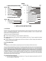
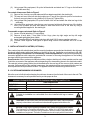
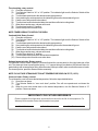
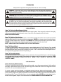
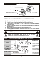
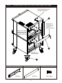
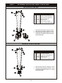
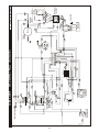
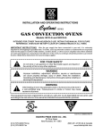
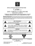
INSTALLATION AND OPERATING INSTRUCTIONS
FULL SIZE
ELECTRIC CONVECTION OVENS
Models: COB-E and COM-E
INTENDED FOR OTHER THAN HOUSEHOLD USE
RETAIN THIS MANUAL FOR FUTURE REFERENCE
OVEN MUST BE KEPT CLEAR OF COMBUSTIBLES AT ALL TIMES
!
FOR YOUR SAFETY: Do not store or use gasoline or other flammable vapors and
liquids in the vicinity of this or any other appliance.
!
!
WARNING: Improper installation, adjustment, alteration, service or maintenance
can cause property damage, injury or death. Read the Installation, Operating and
Maintenance Instructions thoroughly before installing or servicing this equipment.
!
!
WARNING: Initial heating of oven may generate smoke or fumes and must be
done in a well-ventilated area. Overexposure to smoke or fumes may cause
nausea or dizziness.
!
This equipment has been engineered to provide you with year round dependable service when used
according to the instructions in this manual and standard commercial kitchen practices.
Form # 8898450 7/07
Phone:
Fax:
Toll Free:
Website:
E-mail:
(864) 963-3471
(864) 963-5316
(800) 927-6887
www.bkideas.com
[email protected]
BKI Worldwide Headquarters
PO Box 80400
Simpsonville, SC 29680-0400 USA
1
INDEX
I. INSTALLATION INSTRUCTIONS
SECTION
A
B
C
D
E
F
G
H
ITEM
Receiving
Set-up/Mounting
Installation with Casters
Location & Minimum Clearances
Electrical Connections
Flue Connection Ventilation
Initial Cleaning
System Check - Rotary Controls
PAGE
2
2
3
3
4
4
4
5
II. OPERATING INSTRUCTIONS
SECTION ITEM
PAGE
A
General Instructions
5
B
Operation Sequence For Rotary Controls 5
1. Cook Only
5
6
2. Timed Cooking
SECTION ITEM
3. Cook & Hold
4. Steam Injection (Optional)
5. Oven Cool Down
C Cleaning
D
Servicing
1. Stacking Instructions
2. Leg Assembly Instructions
E
Wiring Diagrams
1. Single Phase 208V or 240V
Wiring Diagram (Dial Control)
2. Three Phase 208V or 240V
Wiring Diagram (Dial Control)
3. Single Phase 208V or 240V
Wiring Diagram (CH-100 Control)
4. Three Phase 208V or 240V
Wiring Diagram (CH-100 Control)
F
Parts List w/Exploded View
Warranty
PAGE
6
6
6
7
8
9
10
11
11
12
13
13
14
16
I. INSTALLATION INSTRUCTIONS
A. RECEIVING
Read the notice on the outside carton regarding damage in transit. Damage discovered after opening the
carton is “CONCEALED DAMAGE.” Carrier must be notified immediately to send an inspector and to
furnish forms for claims against the carrier.
When the oven arrives, it should consist of:
!
!
!
A crate or carton containing your new oven (two for a stacked unit).
A carton containing four 31” legs with mounting hardware (set of four 6” legs is supplied for stacked
installations).
A carton containing a Flue Adapter and a Draft Hood. Optional: for Direct Venting (Not available for
European Community Countries).
B. SET UP / MOUNTING:
NOTE:
This appliance must be installed by competent personnel in accordance with the rules in force.
Your oven will be packed sitting on its bottom. The skid may be left under the oven for convenience in further
handling. Unpack carefully, avoiding damage to the Stainless Steel front and/or trim. If concealed damage
is found, follow the instructions detailed in Section A (Receiving). Keep the area around the ovens free and
clear of combustible materials. Do not store any materials on top of or under any oven. The provision of
adequate air supply to your oven for ventilation is essential. As a minimum, observe the clearances detailed
in Section D (Location). Provide adequate ventilation and make up air in accordance with local codes.
Servicing your oven is done through the front control panel and right side access cover. Ensure that these
areas are kept unobstructed for easy access.
For a single unit: Refer to Figure 4
(1) Tilt Oven over to left-hand side and attach two 31” legs on the right-hand side with four 3/8-16”
bolts and washers. Tighten firmly.
2
(2)
Using proper lifting equipment, lift up the left-hand side and attach two 31” legs on the left-hand
side the same way.
For a stack of two ovens: Refer to Figure 3
(1) Remove flue from top oven and replace with flue-adaptor supplied in the stacking kit.
(2) Tilt lower unit over to the left side and position two 6" legs on the right side (one for front and one
for back), secure in place by using 4 bolts (3/8-16) per leg. Tighten firmly.
(3) Using proper lifting equipment, lift up the left side of the unit and attach the other two legs in the
same way.
(4) Using the lifting equipment, raise the top oven to proper height and slide onto top of the bottom
oven. Line up sides and front and fasten to each other at the rear of the units by using a
mounting bracket supplied in the stacking kit.
To assemble an open rack stand: Refer to Figure 2
(1) Loosen 12 bolts (attaching 31” legs) slightly.
(2) Remove 4 inner bolts, 1 from each of the 4 legs, place top right angle and top left angle
underneath and tighten these 4 bolts.
(3) Insert “Open Rack Shelf” and tighten into place with eight 3/8-16 screws, washers and nuts.
(4) Position “Rack Supports” and tighten in place using 4 each of flat washers and 5/16-18 Hex
Nuts.
C. INSTALLATION WITH CASTERS (OPTIONAL):
Four casters (two with wheel brakes) and the mounting hardware are packed and included in the shipment
if ordered. Install casters with wheel brakes on the front of the unit. Installation must conform to UL 197:
Electrical Supply Connections For Permanently Connected Appliances. It requires that permanently
connected appliances with casters be provided with a means for securing the appliance to the building
structure to limit the movement of the appliance.
Oven Restraint: When casters are installed on either a single or double unit, a fixed restraint must be used
to limit the movement of the appliance without depending on or transmitting stress to the electrical conduit.
The restraint (a heavy-gauge cable) should be attached to the rear legs of the oven on which casters are
mounted. If disconnection of the restraint is necessary, the restraint must be reconnected after the oven has
been repositioned in its permanent location. The appliance shall be installed using flexible conduit.
D. LOCATION AND MINIMUM CLEARANCES:
Move the oven to its final location keeping the minimum clearance from the back of the oven to the wall. This
clearance is necessary for safe operation and to provide proper air flow.
MINIMUM CLEARANCES FROM COMBUSTIBLE AND NONCOMBUSTIBLE CONSTRUCTION
Under Ventilation Hood
RIGHT WALL
1”
LEFT WALL
1”
3”
REAR WALL
!
Suitable for installation on combustible floor when installed with legs or casters
provided.
!
!
CAUTION: Do not set the oven with its back flat against the wall. It will not operate
properly unless there is at least three inches breathing space behind the oven
!
!
NOTICE: Local codes regarding installation vary greatly from one area to another.
The National Fire Protection Association, Inc., states in it’s NFPA 96 latest edition
that local codes are “authority having jurisdiction” when it comes to requirements for
installation of equipment. Therefore, installations should comply with all local codes.
!
3
E. ELECTRICAL CONNECTION:
Install according to the spacing requirements listed in the installation section of this manual. We strongly
recommend having a competent professional install this equipment. A licensed electrician should make the
electrical connections and connect power to the unit. Local codes should always be used when connecting
these units to electrical power. In the absence of local codes, use the latest version of the National Electrical
Code.
Note: For supply connections use No. 6 AWG wires suitable for at least 90°C.
The oven, when installed, must be electrically grounded in accordance with local codes and/or the latest
edition of the National Electrical Code ANSI/NFPA No. 70 in the USA (Canadian Electrical Code CSA
Standard C22.1, Part 1 in Canada).
In Europe, the appliance must be connected by an earthen cable to all other units in the complete
installation and, thence, to an independent earth connection in compliance with EN 60335-1 and/or local
codes.
Electrical power is to be supplied to the oven(s) by means of hard wiring, which is to be performed by a
qualified licensed electrician.
a) Adequate means must be provided to limit the movement of the appliance without depending on
or transmitting stress to the electrical conduit.
b) The location(s) where restraining means are to be attached to the appliance shall be specified.
c) The appliance shall be installed using flexible conduit.
COB-E, COM-E
Motor-50hz
Amps
Model
COB-E, COM-E
KW Voltage Phase
10.5
10.5
10.5
10.5
208
208
220-240
220-240
1
3
1
3
Line 1
Line 2
Line 3
N
48
30
44
26
48
30
44
26
28
24
-
Motor-60hz
RPM RPM RPM RPM
(Low) (High) (Low) (High)
725
725
725
725
1425
1425
1425
1425
850
850
850
850
1725
1725
1725
1725
Each oven requires separate electrical connections!
Normal factory connections are made for 208 V. A.C. or 208/240 V.A.C., 60 hz.
This unit is provided with a permanently lubricated electric motor. A wiring diagram may be found on the
back of the service panel on the right-hand side and also in this manual.
F. FLUE CONNECTION VENTILATION:
Installation under ventilation hood (standard):
Local inspectors and ventilation specialists should be consulted so that the design and the installation of the
hood conform to local/municipal codes. In the U.K., follow ventilation requirements as detailed in B.S. 5440.
NOTE: DO NOT PUT A DAMPER IN THE FLUE AND DO NOT CONNECT A BLOWER DIRECTLY TO
THE FLUE.
If the flue runs directly to the free air outside the building, use a wind deflector or a UL listed vent cap at the
end of the pipe. Termination of the vent must be at least two feet above the highest part of the roof within ten
feet. REF: AGA CATALOG NO. Xh0474.
G. INITIAL CLEANING :
Always clean equipment thoroughly before first use. Clean the protective oil from the metal parts and
interior of baking chamber with a solution of washing soda or the other grease dissolving material.
4
H. SYSTEM CHECK- ROTARY CONTROL (standard):
(1)
(2)
Open the oven door.
Turn Selector Switch to “HI.” The green indicator light near Selector Switch and oven light will
illuminate.
(3) Close the door. Oven lights will go off and fan will run. Make sure fan is rotating clockwise looking
from front.
(4) Press Oven Light switch. Oven light will go on and will go off as switch is released.
(5) Turn the thermostat knob. The amber indicator light near the thermostat will illuminate and the
heating elements will come on.
(6) Turn the timer knob past 10 minutes and back to 2 minutes. At the end of 2 minutes the buzzer
will sound. Reset by turning to “0.” All settings below 10 minutes require turning past 10 minutes
and then back to the time required.
(7) Open the oven doors. Oven lights will go on and elements and fan will go off.
(8) Turn Selector Switch to “Cool Down” position. The fan will run to cool down the oven.
(9) Turn Selector Switch to “0” position.
(10) Close the oven doors.
NOTE: WITH THE DOORS CLOSED, THE POWER SWITCH “ON” AND THE SELECTOR SWITCH IS IN
ANY POSITION OTHER THAN “0”, THE OVEN WILL START HEATING AS SOON AS THE SET
TEMPERATURE IS HIGHER THAN THE OVEN TEMPERATURE.
THERMOSTAT INDICATOR LIGHT GOES OUT WHEN OVEN REACHES SET TEMPERATURE AND
COMES ON WHEN OVEN IS HEATING UP.
IN THE EVENT OF POWER FAILURE, THE OVEN WILL NOT OPERATE.
!
PROGRAMMING MENUS: See Operating/Programming Instruction Booklet for
Programmable Oven Control with this option.
!
II. OPERATING INSTRUCTIONS
A. GENERAL INSTRUCTIONS:
(1)
(2)
(3)
(4)
This equipment has an Electronic Temperature Control.
Due to increased efficiency of this oven, the temperature of standard recipes may be reduced
50°F (30°C).
Always load each shelf evenly. Space pans away from each other and from sides and back of
oven to allow maximum air flow between them.
Large tempered glass windows and interior lights allow a close check on the product making it
unnecessary to frequently open the doors. Products cook faster in a convection oven as
compared to a conventional oven. Depending on the product and the type of pans used, time
saving may run from 20 percent to as high as 50 percent.
B. OPERATION SEQUENCE ROTARY CONTROL:
Cook only rotary control:
(1) Close the oven doors.
(2) Turn Selector Switch to “HI” or “LO” position. The indicator light near the Selector Switch will be
illuminated.
(3) Turn the thermostat knob to the desired cooking temperature.
(4) Upon reaching the set temperature, the indicator light near the thermostat will go out.
(5) Load the oven with product to be cooked.
(6) Remove the product from the oven when done.
5
Timed cooking rotary control:
(1) Close the oven doors.
(2) Turn Selector Switch to “HI” or “LO” position. The indicator light near the Selector Switch will be
illuminated.
(3) Turn the thermostat knob to the desired cooking temperature.
(4) Upon reaching the set temperature, the indicator light near the thermostat will go out.
(5) Load the oven with product to be cooked.
(6) Turn the timer knob to the desired bake time and timer will start counting down.
(7) When timer reaches zero, a buzzer will sound.
(8) Turn the timer knob to “O” position.
(9) Remove the product from the oven.
NOTE: TIMER DOES NOT CONTROL THE OVEN.
Cook and Hold Rotary Control:
(1) Close the oven doors.
(2) Turn Selector Switch to “HI” or “LO” position. The indicator light near the Selector Switch will be
illuminated.
(3) Turn the thermostat knob to the desired cooking temperature.
(4) Upon reaching the set temperature, the indicator light near the thermostat will go out.
(5) Load the oven with product to be cooked.
(6) Turn the timer knob to the desired bake time and timer will start counting down.
(7) When timer reaches zero, a buzzer will sound.
(8) Turn the Timer knob to “O” position.
(9) Turn the thermostat knob to the desired hold temperature.
(10) Remove the product from the oven when done.
Optional steam injection Rotary control:
The solenoid valve for steam injection is mounted behind the service panel on the right-hand side of the
unit. The electronic timer is preset at the factory. A ¼” copper tubing is provided on the Solenoid Valve for
water hookup with a compression fitting. After the water hookup is made, make sure that there are no leaks.
For steam injection, press the Steam switch momentarily.
NOTE: DO NOT USE STEAM INJECTION AT TEMPERATURES BELOW 275°F (135°C).
Oven cool down Rotary control:
To cool down the oven to a lower desired temperature, follow the steps detailed below.
(1) Open the oven doors.
(2) Turn Selector Switch to “oven cool down” position. Fan will now operate and cool down the
oven.
(3) When the oven has cooled down to the desired temperature, turn the Selector Switch to “O”
position. Close oven doors.
IMPORTANT FOR FUTURE REFERENCE
Please complete this information and retain this manual for the life of the equipment. For
Warranty Service and/or Parts, this information is required.
Model Number
Serial Number
6
Date Purchased
CLEANING
Always clean equipment thoroughly before first use. Clean unit daily.
!
WARNING: To avoid any injury, turn the power switch off at the fuse disconnect switch/circuit
breaker or unplug the unit from the power source and allow to cool completely before performing
any maintenance or cleaning.
!
!
WARNING: Unit is not waterproof. To avoid electrical shock or personal injury, DO NOT submerge
in water. DO NOT operate if it has been submerged in water. DO NOT clean the unit with a water jet.
DO NOT steam clean or use excessive water on the unit.
!
!
CAUTION: Use mild detergent or soap solution for best results. Abrasive cleaners could scratch
the finish of your unit, marring it’s appearance and making it susceptible to dirt accumulation. DO
NOT use abrasive cleaners or cleaners/sanitizers containing chlorine, iodine, ammonia or bromine
chemicals as these will deteriorate the stainless steel and glass material and shorten the life of the
unit. Use nylon scouring pads. DO NOT use steel wool.
!
OVEN INTERIOR:
Clean The Racks And Rack Support Guides:
Open the doors and remove all wire racks and rack support guides. Take them to the sink and thoroughly
clean in warm water with mild detergent or soap. Use a nylon scouring pad or stiff nylon brush.
DO NOT USE STEEL WOOL.
Clean The Stainless Steel Interior:
Baked on splatter, oil, grease or discoloration on the stainless steel inside of the oven may be removed with
stainless steel cleaner, or any other similar cleaning agent. NEVER use vinegar or any corrosive cleaner.
Use only cleaners approved for stainless steel. NEVER use cleaning solvents with a hydrocarbon base.
NEVER use a wire brush, steel or abrasive scouring pads, scraper, file or other steel tools.
NOTE: ALWAYS RUB THE STAINLESS STEEL ALONG THE GRAINS.
Clean The Blower Wheel:
To clean the blower wheel, remove and immerse in ammoniated water for 20 to 25 minutes. Then, scrub it
off with a small, stiff brush. The same procedure can be followed for wire racks and rack supports. To
remove the blower wheel, loosen the set screws (2) on the hub of the blower wheel and tighten the 3/8”
wheel puller bolt (supplied) in center of hub (See Fig. 1).
Clean The Porcelain Interior:
Porcelain enamel interiors are designed to be as maintenance free as possible. However, for best results,
the oven should be cleaned regularly. Enameled interiors can be easily cleaned with oven cleaners. KEEP
CLEANING FLUIDS AWAY FROM ELECTRICAL WIRES, LIGHT SOCKETS, SWITCHES AND
CONTROL PANEL.
OVEN EXTERIOR:
Clean The Exterior Stainless Steel:
To remove normal dirt or product residue from stainless steel, use ordinary soap and water (with or without
detergent) applied with a sponge or cloth. Dry thoroughly with a clean cloth. Never use vinegar or corrosive
cleaner. Do not use chorine based cleaners.
To remove grease and food splatter or condensed vapors that have baked on the equipment, apply
cleaners to a damp cloth or sponge and rub cleanser on the metal in the direction of the polished lines on the
metal. Rubbing cleanser as gently as possible in the direction of the polished lines will not mar the finish of
the stainless steel. To remove discoloration, use a non-abrasive cleaner. NEVER use a wire brush, steel or
abrasive scouring pads, scraper, file or other steel tools. NEVER RUB WITH A CIRCULAR MOTION.
7
Cleaning The Blower Wheel
Figure 1
Blower Wheel
Set Screws (2)
Motor
Wheel Puller Bolt 3/8”-Hex
D. SERVICING:
NOTE: THIS APPLIANCE MUST BE SERVICED BY AN AUTHORIZED SERVICE AGENT.
(1)
(2)
(3)
(4)
(5)
(6)
(7)
Power supply to the unit must be disconnected before any service is performed.
Most of the service on the unit can be performed from the front and/or control panel side.
For proper servicing, access to the control panel side of the unit will be required.
It will be necessary to have access to the back of the oven for service needs related to the
electric power supply.
A system wiring diagram is provided in this manual and on the back of the service panel on the
right side of the oven.
All servicing should be performed by a factory-authorized technician only.
For proper maintenance and repairs, call the factory toll free (800-972-6887) for an authorized
service agency in your area.
!
WARNING: RISK OF FIRE. When stacked two high maximum, use stacking kit
part # E3771A only.
!
!
CAUTION: This product, when stacked, has more than one power-supply
connection point. Disconnect all power supplies before servicing.
!
Figure 2
OPEN RACK STAND ASSEMBLY INSTRUCTIONS: COB-E & COM-E
770504
Lock Nut 1/4-20 (12)
Oven Base
Assembly Instructions
8507600
Washer, Flat 1/4" (12)
8205500
Screw, 1/4-20 X ½ (12)
21818222
Support, Lt Open Rack (2)
21816807
Support, Wire Rack (2)
2: Place open rack supports
between legs and secure
with ¼-20 UNC screw, flat
washer and locknut.
770504
Lock Nut 1/4-20 (12)
21818234
Undershelf, Gas Oven (1)
8205500
Screw, 1/4-20 X ½ (12)
1: Place undershelf between
legs & secure with ¼-20
UNC screw, flat washer &
locknut. The holes for
mounting the wire racks
should be toward the front
of the oven.
3: Slide open wire racks into
position using the holes in
the undershelf as a guide.
Open Style Support Leg
8
Figure 3
STACKING INSTRUCTIONS FOR: COB-E & COM-E CONVECTION OVENS
Remove flue from top oven
and replace with item 1
1
Attach part #
21818062 with
6 each 8-32
stainless screws
Remove flue from
bottom oven, and
re-install after top
oven is in place.
2
Material: 14 ga
201 Stainless
3
Item 1
Item 2
E3770A
Item 3
E3771A
9
3/8”-16 Bolt
Figure 4
LEG ASSEMBLY INSTRUCTIONS - MODEL: COB-E & COM-E
WITH PLATE CASTER
2
1
Item
1
2
3
4
5
6
7
7
6
4
3
45
1.
2.
3.
65
23
P/N
21796810
8633102
8227700
8509300
8435000
82447-00
8633101
Description
Weldment, Oven Leg
Caster, 5” Swivel W/Top Plate
Hex Hd 5/16-18 X ¾ Bolt #5 Zn
Washer, Flat SAE, 5/16
Hex-nut 5/16-18
Hex Hd. 3/8-16 X .750 #5
Caster, 5" Swivel W/Plate & Brake
Attach two item 2 to two item 1 using item 3, 4 and 5.
Attach two item 7 to two item 1 using item 3, 4 and 5.
Using proper lifting equipment attach item 1 to the
corresponding hole patterns located in the bottom
of the oven with item 6.
8
7
WITHOUT PLATE CASTER
2
1
Item
1
2
3
4
5
6
7
6
1.
2.
4
3
45
56
23
10
P/N
21796810
8633515
8227700
8509300
8435000
82447-00
Description
Weldment, Oven Leg
Foot Insert, Adjustable
Hex Hd 5/16-18 X 3/4 Bolt #5 Zn
Washer, Flat, SAE, 5/16
Hex-Nut 5/16-18
Hex Hd. 3/8-16 X .750 #5
Attach four item 2 to four item 1 using item 3, 4 and 5.
Using proper lifting equipment attach item 1 to the
corresponding hole patterns located in the bottom
of the oven with item 6.
11
29
NC
NO
Doors Close To
Activate Switch
C
30
27
1
18
2
19
T1 T3
Power
Timer
28
1
4
4
15
9
Buzzer
23
25
21
14
Cooling Fan
50
T-Stat Relay
T6 T7 T8 T9T10T11
Thermostat
T4 T5 T2
Probe
23
RTD Probe
Amber Pilot Light
Light Push
Button
Switch
Green Power Light
COB-E & COM-E
43
29
22
17
26
24
10
16
44
Fuse Box
3
6
45
208, or 240VAC, 1 Phase
46
L1
L2
9
(Dial Control)
8
Lights
47
48
7
13
6
49
12
2 Speed
1725/850
39
Single Phase
208 or 240V
38
11
5
1
41
A2
A1
32
37
36
4 Pole 40 Amp
Contactor
35
T3 to T2
T1 to T2
34
L2
2
T1 to T4
Ground Stud
42
L2
L1 L1
33
Centrifugal
Switch
Front
Element
L1 L3 L2
Com
3
Motor
4
E. WIRING DIAGRAMS
12
29
NC
NO
Doors Close To
Activate Switch
C
30
27
1
18
2
19
23
Power
1
Timer 4
4
15
21
14
Cooling Fan
50
25
23
9
Buzzer
T-Stat Relay
T6 T7 T8T9T10T11
Thermostat
T1T3
RTD Probe
Amber Pilot Light
T4 T5T2
Probe
Light Push
Button
Switch
28
Green Power Light
22
43
29
17
26
24
10
16
44
COB-E & COM-E
Fuse Box
6
3
45
46
L1
208, or 240VAC, 3 Phase
L2
9
8
Lights
47
48
7
13
6
49
12
2 Speed
1725/850
(Dial Control)
L1
38
11
5
L3
39
1
42
L1
L2
L2
Low
4 Pole 40 Amp
Contactor
35
T3 to T2
T1 to T4
T1 to T2
34
L4
36
L3
37
2
High
Ground Stud
41
A2
A1
32
33
Centrifugal
Switch
Front
Element
Three Phase
208 or 240V
Com
3
Motor
4
Centrifugal Switch
Single Phase 208V or 240V Wiring Diagram (CH-100 Control)
18
2
1
27
CENTRIFUGAL SWITCH
FAN
MOTOR MOTOR
6
FUSE BOX
8
7
46
6
19
27
T1TOT4
T1TOT2
3
18
10
29
COM
T3TOT2
24
DOOR
47
45
44
PROBE
FRONT
ELEMENT
9
32
4
33
GND
FAN
20
LOW
2
CENTRIFUGAL SWITCH
RELAY
HEAT
1
48
23
22
28
HIGH
4
37
36
35
34
21
A1
5
26
25
4 POLES, 40 AMPS
CONTACTOR
A2
11
38
10
LIGHTS
39
41
9
12
42
13
Ground
Stud
16
POWER
L1 L3 L2
SINGLE PHASE
17
NC
15
C
208/ 240V
14
NO
DOORS ACTIVATE
SWITCH WHEN
CLOSED
30
31
Three Phase 208V or 240V Wiring Diagram (CH-100 Control)
18
2
1
27
CENTRIFUGAL SWITCH
6
FUSEOX
B
8
46
6
19
27
COM
T1TOT4
T1TOT2
3
18
10
29
CENTRIFUGAL SWITCH
T3TOT2
24
DOOR
45
44
PROBE
47
7
9
FRONT
ELEMENT
32
4
33
GND
FAN
20
LOW
1
2
MOTOR
RELAY
HEAT
4
48
23
22
28
HIGH
FAN
MOTOR
37
36
35
34
21
5
26
25
A1
4 POLES, 40 AMPS
CONTACTOR
A2
11
38
10
LIGHTS
39
9
12
41
42
13
Ground
Stud
16
POWER
L1 L 3 L 2
THREE PHASE
17
NC
C
15
208/240V
14
NO
DOORS ACTIVATE
SWITCH WHEN
CLOSED
30
31
COOLING
FAN
13
14
93
93
1
100
100
3
99
99
1
98
98
1
P/N
M1114X
M1115X
N3039A
N3040A
N5831A
N3041A
N5814A
N5815A
N1019X
M1231A
M1176X
M1049X
86
86
1
89
1
89
120
120
1
119
119
1
85
85
1
115
115
2
107
107
1
95
95
1
52
52
1
27
27
5
114
114
2
118
118
1
101
101
1
54
54
2
49
2
50 49
50
6
43
1
43
50
50
6
61
61
1
76
76
8
38
38
2
122
122
1
53
53
1
79
79
4
5
51
1
71
71
2
21
21
2
80
80
1
4
4
1
30
30
1
111
111
1
DETAIL “B”
33
33
1
38
38
2
44
44
1
55
55
1
45
45
1
48
63
63
6
13
13
1
83
83
2
121
121
3
69
69
1
60
17
17
2
60
2
11
11
1
COB-E & COM-E CONVECTION OVEN
Description
Kit, 25" Legs, Black w/3" Adj Feet
Kit, 25" Legs, Black w/Plate Casters
Kit, 25" Legs, S/S w/3" Adj Feet
Kit, 25" Legs, S/S w/Plate Casters
Kit, Stacking, w/6" Adj Legs
Kit, Stacking, w/Plate Casters
Kits (Not Shown)
91
91
1
123
32
32
2
29
29
1
105
1
102
102
1
104
104
1
108
108
2
105
112
113
112
113
2
2
DETAIL “A”
97
97
1
90
90
1
P/N
E8752A
E8753A
E8754A
E8755A
E8756A
E8759A
92
1
106
106
1
92
Description
Solenoid Valve
Coil (For Solenoid Valve)
1/8 Brass Coupling
1/8 Brass Elbow
1/8x4" Brass Nipple
1/8NPT-1/4 Compression Fitting
1/8x2 3/8 Nipple
1/4 Tubing x 9"
Steam Injection Nozzle
Steam Timer, 208/230V
Steam Potentiometer
Momentary Switch (Steam)
Steam Option (Not Shown)
F. PARTS LIST w/EXPLODED VIEW
31
31
1
“A”
20
20
1
10
10
1
991
23
23
1
37
37
1
“B”
74
74
1
58
58
1
72
72
1
34
34
1
24
24
1
62
62
1
47
47
1
75
75
1
88
88
1
ITEM
P/N
1*
2*
3
4
5
6*
7*
8*
9
10
11
12*
13
14*
15*
16*
17
18*
19*
20
21
22*
23
24
25*
26*
27
28*
29
30
31
32
33
34
35*
36*
37
38
39*
40*
41*
42*
43
44
81300-00
8410400
21816853
1200500
21816859
21818043
8162500
43813149
218168-40
21816854
21816841
81408-00
21816842
21816877
21816869
82306-00
21816875
218180-47
8508100
218180-46
21816807
218180-45
21816813
21816871
218180-48
218180-44
21816806
21818049
21816858
21816857
21816833
21818037
21816896
21816863
8211100
82447-00
218168-62
89671-00
21816861
21818034
21818040
8357600
1300240
M1030X
1300205
21816897
11019-00
5161000
21816852
8400450
8400430
8400420
21816819
21816821
218168-05
1215400
21816810
81357-00
21816860
1400150
21816892
21818075
45
46*
47
48
49
50
51*
52
53
54
55
56*
57*
58
60
61
62
DESCRIPTION
QTY ITEM
8-32 X 3/8 Type T
Nut, Hex, 8-32 S/S
Support, Lower Back Liner
Fan, Wheel In Wheel Blower
Bottom Channel
Leg Mount
M/S #10-32 Truss Hd
Label, Warning Hot Surface (French)
Panel, Top Outer
Pan, Base
Chamber, Oven Lower
8-32 X ½ MS
Bake Liner Upper
Cover, w/Cut-Out
Base, Cover w/Cut-Out
5/16-18 X 1.25 Bolt Hx
Support, Small Light
Insulation, Bottom Conv Oven
Lock Washer Ext 1/4
Insulation, R.H. Side
Support, Wire Rack
Insulation, L.H. Side
Bake Liner, Back
Flue, End
Insulation, Top
Insulation, Back
Rack, Full Size
Insulation, Filler
Support, Top Door
Frame, Front
Insert, Control Panel
Spacer Door
Seal, Top
Retainer, Right Insulation
Screw, Mach 1/4-20 X 3/4
Hex Hd. 3/8-16 X .750 #5
Panel, Right Outer
Bushing, Snap 1.312 I.D.
Baffle, Control Panel
Spacer, Insulation
Tube Cord Tube Weldment
Rivet, 3/16 X 3/8 Al
Switch, Door
208V Contactor
240V Contactor
Seal, Bottom Door
Connector, 1/2" Flex Straight
Connector Cable Romex
Panel, Left Outer
Roll Pin .250 X 1.250 (COM Only)
Flange Bearing (COM Only)
Thrust Bearing
60 Arm Weldment
Arm, 40 Weldment
Sprocket, Door (COM Only)
Fan W/ Motor
Switch Cam
Screw, 8-32 X 3/8" Ft Hd
Retainer Back Insulation
Assy, Snap In Light 230V/15W
Baffle, Oven
Pan Cover
118
12
1
1
1
4
6
1
1
1
1
12
1
1
1
4
2
2
6
1
2
1
1
1
1
1
5
4
1
1
1
2
1
1
4
33
1
2
1
8
1
84
1
1
1
1
2
1
1
2
6
4
1
1
2
1
1
5
1
2
1
1
63
65*
66*
67*
68*
69
70*
71
72
73*
74
75
76
77*
78*
79
80
81*
82*
83
84*
85
86
87*
88
89
90
91
92
93
94*
95
96*
97
98
99
100
101
102
103*
104
105
106
107
108
109*
110*
111
112
113
114
115
116*
117*
118
119
120
121
122*
123
P/N
21816870
21816868
21816844
8354000
84252-00
21816835
8435000
21816864
1219600
43813103
8806650
8861000
21816865
1000900
8967200
218168-20
1400120
89456-00
21818033
31007-33
8203400
21816851
8825300
81759-00
21816899
21816850
21816883
21816827
1300210
1300220
21809210
21809220
1300230
1400110
1400130
1509600
45653000
8704600
88250-00
21816895
21816825
1400140
11072-00
1504800
U1451A
3110007
8172400
21816834
21816832
21816804
21816816
21816814
84004-10
8400440
82082-00
21816843
8716100
21818019
L6803A
L6809A
1107500
S6808A
* = NOT SHOWN
15
DESCRIPTION
Support, Element
Motor Panel
Motor Mount
Pop Rivet, Ø.125 X .297
Nut, Hex, 1/4-20 SS
Front Cover
Hex-nut 5/16-18 ZN
Seal, Left & Right Door
Motor 200-230v 850/1725 RPM
Label, Wiring, Hot Surface
Label, Elec Oven 3 Ph 208/240V Schematic
Label, Spec
Support, Side Rack
Sleeve, Fibgls, #3 Wire X .020wl
Bushing, Snap .375 ID .5 Hole Nylon Black
Bracket, Baffle
RTD Probe
Clamp-Loop 3/16”
Spacer, Probe
Guard, Fan Finger
M/S Ft Hd Ph 1/4-20x 5/8 ZN
Trim, Top
Decal, Leg
10-32 X 1/2 Tr Hd
Conduit 1" 36" Long
Trim, Bottom
Control Panel, Basic W/Assembly
Door,60 w/Window Assy
Switch, 4 Pos Rotary
Switch, Rocker DPST
Decal, Black & Red w.o./Steam
Decal, Black & Red w/Steam
Switch, Push Button
Thermostat, Fastron G6
60 Min Timer
Pilot Light Green (Power)
Light, Indicator 250V, 1/2" Dia. Amber
Knob
Decal, Caution Disconnect
Bracket, Buzzer
40 Door w/Window
Audio Alarm
Block Terinal, 6 Station 600V
Holder, Fuse 15A 600V
Nameplate, BKI 8”
Fuse,300V,15A
M/S Ft Hd PH 10-32x1/2 SS
Support, Door
Stop, Door
Chain, Roller #35 (COM Only)
Short Eye Hook (COM Only)
Long Eye Hook (COM Only)
Turnbuckle, 1/4-20 (COM Only)
Nut, Hex, Lt Hand 1/4-20 SS (COM Only)
1/4-20 X .75 Tr Hd
Plate, Cover
Catch, Roller (COM Uses1, COB Uses 2)
Plate, Striker (COM Uses1, COB Uses 2)
Element, 208 V, 3333W
Element, 230 V, 3333W
Block, 4 Pole Terminal, 85 Amp
Handle Assy (COM Uses1, COB Uses 2)
QTY
6
1
1
22
10
1
12
2
1
1
1
1
8
1
1
4
1
1
1
2
4
1
1
4
1
1
1
1
1
1
1
1
1
1
1
1
1
3
1
1
1
1
1
1
1
2
4
1
1
2
2
2
2
2
2
1
1
1
3
3
1
1
BKI LIMITED WARRANTY
PO Box 80400 Simpsonville, SC 29680-0400 USA
(864) 963-3471 ♦ Toll Free: (800) 927-6887 ♦ Fax: (864) 963-5316
WHAT IS COVERED
This warranty covers defects in material and workmanship under normal use, and applies only to the original purchaser
providing that:
♦ The equipment has not been accidentally or intentionally damaged, altered or misused;
♦ The equipment is properly installed, adjusted, operated and maintained in accordance with National and local codes. and
in accordance with the installation instruction provided with the product;
♦ The serial number rating plate affixed to the equipment has not been defaced or removed.
WHO IS COVERED
This warranty is extended to the original purchaser and applies only to equipment purchased for use in the U.S.A.
COVERAGE PERIOD
Convection Ovens: COB Models: One (1) Year limited parts and labor; COM Models: Two (2) Year limited parts and labor;
CO1 Models: Two (2) Year limited parts and labor; (5) Year limited door warranty.
Warranty period begins the date of dealer invoice to customer or ninety (90) days after shipment date from BKI - whichever
comes first.
WARRANTY
COVERAGE
This warranty covers on-site labor, parts and reasonable travel time and travel expenses of the authorized service
representative up to (100) miles. round trip, and (2) hours travel time.
EXCEPTIONS
The extended door warranty years 3 through 5 is a parts only warranty and does not include labor, travel, milage or any other
charges.
EXCLUSIONS
♦
♦
♦
♦
♦
♦
♦
♦
♦
♦
♦
♦
♦
♦
♦
INSTALLATION
Leveling. as well as proper installation and check out of all new equipment - per appropriate installation and use materials - is
the responsibility of the dealer or installer, not the manufacturer.
REPLACEMENT
PARTS
BKI genuine Factory OEM parts receive a (90) day materials warranty effective from the date of installation by a BKI Factory
Authorized Service Center.
Negligence or acts of God,
Thermostat calibrations after (30) days from equipment installation date,
Air and Gas adjustments,
Light bulbs,
Glass doors and door adjustments.
Fuses,
Adjustments to burner flames and cleaning of pilot burners,
Tightening of screws or fasteners.
Failures caused by erratic voltages or gas supplies,
Unauthorized repair by anyone other than a BKI Factory Authorized Service Center,
Damage in shipment,
Alteration, misuse or improper installation,
Thermostats and safety valves with broken capillary tubes.
Freight - other than normal UPS charges,
Ordinary wear and tear.
This Warranty is in lieu of all other warranties, expressed or implied, and all other obligations or liabilities on the manufacturers part. BKI shall in no
event be liable for any special, indirect or consequential damages, or in any event for damages in excess of the purchase price of the unit. The repair or
replacement of proven defective parts shall constitute a fulfillment of all obligations under the terms of this warranty.
Form #U4177A-BKI 7/07
16