1
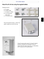
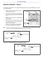
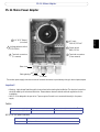
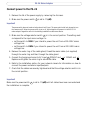
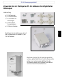
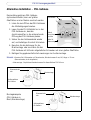
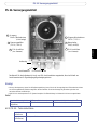
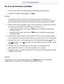
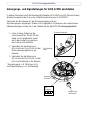
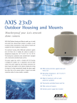
ENGLISH
PS-24 Mains Adaptor
Installation Guide
DEUTSCH
PS-24 Mains Adaptor
Mount the PS-24 box using the supplied holders
Package contents:
a)
b)
c)
d)
4 holders
4 wood screws
4 screws for holders
4 concrete plugs
(5mm drill)
e) 4 concrete screws
(c)
(d)
(b)
(a)
(e)
ENGLISH
Using the supplied screws (c), attach the
plastic holders (a) to the PS-24 box.
Using the appropriate screws for the wall material
(wood or concrete) and the weight of the unit,
mount the PS-24 power supply box on a flat surface
with the glands pointing downwards.
PS-24 Mains Adaptor
Alternative installation - PSU box
The vandal-proof PSU box is an optional accessory which can be mounted either on a pole
or on a flat surface.
1. Remove the top lid of the PSU box by
removing the 4 screws.
Screws
2. Place the PS-24 with the 4 cable glands
in the opening at the bottom of the PSU
box.
3. Replace the lid and lock it by tightening
the 4 screws.
4. Use the holder for the pole mount or use
the supplied screws to mount the PSU on
a pole or a flat surface.
5. Follow the instructions for the outdoor
housing to complete the installation.
Cable
glands
Holder for
pole mount
Note: • Use 4pcs. sleeve anchor with flange nut, drill size 6mm, M6, length >= 50mm (concrete screw, not included).
• Pole mount - the recommended pole diameter for this pole box is 130-140mm.
Gooseneck
tube
Pole box mounting
Outdoor housing
for camera
Examples of installation (PSU box and pole/wall mount)
Gooseneck
tube
Outdoor housing
for camera
Wall box mounting
PS-24 Mains Adaptor
PS-24 Mains Power Adaptor
AC & DC Output
(not used)
6 AC Input
230VAC/115VAC
5 Voltage selector switch
(115V/230V)
4 Power switch
ON(1) OFF(0)
2 Terminal connectors
(From camera)
1 Terminal connectors
(To camera)
Outer ring
Cable gland
6-12mm 10-14mm
The outdoor power supply contains two sets of terminal connectors to provide easy wiring for alarm inputs/outputs
Important!
• Warning - high voltage. Read through the instructions before starting the installation. The electrical connection
should be made by an authorized electrician. Please observe relevant national and local regulations for the
installation.
• AXIS PS-24 is designed to be part of an IT power system. Ground is not connected internally in the power
supply.
Cables
Power cable (not supplied)
(6) AC Input connector
Copper cables: AWG 16-18 or 1.5mm2
Input cables (not supplied)
(2) Terminal connectors
AWG 16-28 or 1.5mm2 cables
AXIS PS-24 Specifications
AC Input:
100-120VAC / 220-240VAC, max 800mA / 400mA, 80VA
AC Output:
24VAC, max 63VA
ENGLISH
3
PS-24 Mains Adaptor
Connect power to the PS-24
1. Remove the lid of the power supply by removing the 4 screws.
2. Make sure the power switch 4 is set to ‘0’ (off).
Important!
The power switch does not break on both poles at the AC input. The power switch shall only be used to turn
the camera on/off. When the power switch is set to off, high voltage is still present in the AXIS PS-24
mains adaptor. Regard the switch in the building installation as disconnect device.
3. Make sure the voltage selector switch 5 is in the correct position. The setting must
correspond to the input mains voltage i.e.:
• set the switch to 115V if you intend to power the unit from a 100-120V mains
voltage line.
• set the switch to 230V if you intend to power the unit from a 220-240V mains
voltage line.
4. Remove the outer ring of the cable gland, thread the mains cable (not supplied)
through the outer ring and then through the cable gland.
5. Connect the live/ground wires to AC Input 6 (230VAC and
Replace and tighten the outer ring to secure the cable.
or 115VAC and
).
6. Refer to the installation section for your network camera for information on how to
connect the power and alarm inputs/outputs.
7. Check that the cables are securely tightened and that the voltage selector switch is in
the correct position.
Important!
Make sure the power switch 4 is set to ‘0’ (off) until all cables have been connected and
the installation is complete.
PS-24 Mains Adaptor
Connect the AXIS 231D/232D power and alarm inputs/outputs
This document describes how to install the AXIS 231D/232D and the PS-24. Please refer to
the AXIS 231D/232D Installation Guide for further instructions.
Connect the dome camera to the power supply and alarm inputs/outputs* using the
connection cable supplied with the AXIS 231D/232D:
1. Disconnect the outer ring of the cable gland, thread the connection cable through the
outer ring and then through the cable gland.
2. For easy wiring, disconnect the terminal block connectors.
4. Connect any alarm inputs/outputs (input cables not supplied) to the corresponding
pin holes in the connector and fasten the screws.
5. Replace the connectors and replace and tighten the outer ring to secure the cable.
* alarm inputs e.g. doorbell, light and outputs e.g. alarm devices
See the Axis Web site at http://www.axis.com for more information about the available
outdoor housing and mounting accessories.
ENGLISH
3. Following the pinout description on the power supply (inner lid), push the colored
wires into the corresponding pin holes in the connector and tighten the screws. It is
recommended that all wires are connected, even those that are not used in the
installation.
PS-24 Mains Adaptor
Connect the AXIS 225FD power and alarm input/output
This document describes how to install the AXIS 225FD and the PS-24. Please refer to the
AXIS 225FD Installation Guide for further instructions.
Connect the camera to the power supply and alarm input/output* (cables not supplied). For
information on the recommended cable dimensions, please refer to the table on the PS-24
Mains Power Adaptor page.
Power connector block
2. Connect the power cable from the
Terminal Connector (1) in the
PS-24 to the power connector
block in the camera.
A
+ oC
r
GN AC
D
1. Disconnect the outer ring of the
cable gland, thread the cables (not
supplied) through the outer ring
and cable gland.
1
I/O terminal
block
3. Connect the input cable from the
terminal connector (2) in the PS-24
to the I/O terminal block in the
camera.
7
Control
button
* alarm input e.g. doorbell, light and
output e.g. alarm device
Network
connector
LED
indicators
1 2 3 4
Conduit hole
and plug
PS-24-Versorgungsnetzteil
Verwenden Sie zur Montage des PS-24-Gehäuses die mitgelieferten
Halterungen
Lieferumfang:
a) 4 Halterungen
b) 4 Holzschrauben
c) 4 Schrauben für
Halterungen
d) 4 Betondübel
(5-mm-Bohrer)
e) 4 Betonschrauben
(c)
(d)
(b)
(a)
(e)
DEUTSCH
Befestigen Sie die Halterungen (a) mit
den vorgesehenen Schrauben (c) am
PS-24-Gehäuse.
Montieren Sie das PS-24-Versorgungsnetzteil
auf eine glatte Oberfläche. Die Anschlussmuffen
sollten nach unten zeigen. Wählen Sie die
Schrauben passend zum Material (Holz/Beton)
und zum Gewicht des Netzteils aus.
PS-24-Versorgungsnetzteil
Alternative Installation – PSU-Gehäuse
Das zerstörungssichere PSU-Gehäuse
(optionales Zubehör) kann auf glatten
Oberflächen und an Masten montiert werden.
Schrauben
1. Lösen Sie zum Öffnen des PSU-Gehäuses
die 4 Befestigungsschrauben.
2. Legen Sie das PS-24-Netzteil so in das
PSU-Gehäuse ein, dass die
Anschlussmuffen in die entsprechende
Öffnung des PSU-Gehäuses passen.
Kabel
Anschlussmuffen
3. Setzen Sie den Gehäusedeckel wieder
auf, und befestigen Sie die 4 Schrauben.
Halter für
Mastmontage
4. Benutzen Sie die Halterung für die
Mastmontage, oder montieren Sie das
PSU-Gehäuse mit Hilfe der mitgelieferten Schrauben auf einer glatten Oberfläche.
5. Befolgen Sie gegebenenfalls die Anweisungen zur Außenmontage.
Hinweis: •Benutzen Sie 4 Hülsenanker mit Flanschmutter, Bohrdurchmesser 6 mm, M6, Länge >= 50 mm
(Betonschrauben, nicht mitgeliefert).
• Mastmontage – Empfohlener Mastdurchmesser für dieses Gehäuse 130-140 mm.
Schwanenhalsrohr
Mastmontage
Außengehäuse
für Kamera
Montagebeispiele
(PSU-Gehäuse in
Mast-/Wandmontage)
Schwanenhalsrohr
Außengehäuse
für Kamera
Wandmontage
PS-24-Versorgungsnetzteil
PS-24-Versorgungsnetzteil
3
Ausgang
Gleich-/Wechselstrom
(nicht belegt)
6 Eingang Wechselstrom
230 V~ / 115 V~
5 Spannungswähler
(115 V / 230 V)
4 Netzschalter
EIN(1), AUS(0)
Außenring
Anschlussmuffe
6-12 mm 10-14 mm
Das Netzteil für den Außenbereich ist mit zwei E/A-Anschlussleisten ausgestattet, die eine Vielzahl von
Anschlussvarianten für Signaleingänge/Signalausgänge bieten.
Wichtig!
• Achtung! Hochspannung! Lesen Sie die Bedienungsanleitung, bevor Sie mit der Montage beginnen. Elektroarbeiten müssen
von einem ausgebildeten Elektriker ausgeführt werden. Beachten Sie bei der Montage die geltenden regionalen und
nationalen Gesetze und Richtlinien.
• AXIS PS-24 ist als Komponente für IT-Systeme konzipiert. Die Erdverbindung ist im Netzteil nicht intern angeschlossen.
Kabel
Netzkabel (nicht mitgeliefert)
(6) Eingang (Wechselstrom)
Kupferkabel: AWG 16-18 oder 1,5 mm2
Eingangskabel (nicht
mitgeliefert)
(2) E/A-Anschlüsse
AWG 16-28 oder 1,5 mm2 Kabel
AXIS PS-24 – Technische Daten
Eingang
Wechselstrom:
100-120 V~ / 220-240 V~, max. 800 mA / 400 mA, 80 VA
Ausgang
(Wechselstrom):
24 V~, max. 63 VA
DEUTSCH
2 E/A-Anschlüsse
(von Kamera)
1 E/A-Anschlüse
(von Kamera)
PS-24-Versorgungsnetzteil
PS-24 an das Stromnetz anschließen
1. Lösen Sie zum Öffnen der Gehäuseklappe die 4 Befestigungsschrauben.
2. Schalten Sie den Netzschalter 4 auf ‚0‘ (Aus).
Wichtig!
Der Netzschalter unterbricht nicht beide Pole des Wechselstromeingangs. Er dient lediglich zum
Aus-/Einschalten der Kamera. Auch wenn der Netzschalter in Stellung ‚0‘ ist, liegt am AXIS PS-24-Netzteil
weiterhin Hochspannung an. Betätigen Sie zum Ausschalten des Gerätes den Hauptschalter im Gebäude.
3. Setzen Sie den Spannungswähler 5 in die richtige Position. Die Einstellung muss
der Spannung der äußeren Stromversorgung entsprechen, d. h.:
• Setzen Sie den Schalter auf Position 115 V, wenn Ihre Netzstromversorgung
100-120 V liefert.
• Setzen Sie den Schalter auf Position 230 V, wenn Ihre Netzstromversorgung
220-240 V liefert.
4. Lösen Sie den Außenring der Anschlussmuffen, führen Sie das Versorgungskabel
(nicht mitgeliefert) zuerst durch den Außenring und dann durch die Anschlussmuffe.
5. Verbinden Sie Leiter- und Erdungskabel mit dem Wechselstromeingang 6 (230 V~
und
oder 115 V~ und ). Schrauben Sie den Außenring wieder fest auf, um das
Kabel zu fixieren.
6. Informationen zur Verschaltung der Versorgungs- und Signalkabel Ihrer
Netzwerkkamera finden Sie in der Montageanleitung zur Kamera.
7. Vergewissern Sie sich, dass alle Kabel fest sitzen und der Spannungswähler auf der
richtigen Position steht.
Wichtig!
Vergevissern Sie sich dass der Nelzschalter auf ‚0‘ (Aus) gesetzt ist bis alle Kabeln
angeschlossen sind und Sie die Installation abgeschlossen haben.
PS-24-Versorgungsnetzteil
Versorgungs- und Signalleitungen für AXIS 231D/232D anschließen
In diesem Dokument wird die Montage der Modelle AXIS 231D/232D und PS-24
beschrieben. Weitere Hinweise finden Sie in der Installationsanleitung zu AXIS
231D/232D.
Verbinden Sie die Kuppelkamera mit der Stromversorgung und den
Signaleingängen/-ausgängen* mit Hilfe der Kabel, die zusammen mit der AXIS 231D/232D
geliefert wurden:
1. Lösen Sie den Außenring der Anschlussmuffen, führen Sie das Verbindungskabel
zuerst durch den Außenring und dann durch die Anschlussmuffe.
2. Lösen Sie die Anschlussleisten, um die Kabelführung zu erleichtern.
4. Verbinden Sie alle Signaleingänge/-ausgänge (Eingangskabel nicht mitgeliefert) mit
den entsprechende Kontaktlöchern, und ziehen Sie die Schrauben fest.
5. Setzen Sie die Anschlussleisten wieder auf, und schrauben Sie den Außenring fest
auf, um das Kabel zu fixieren.
* Signaleingänge, z. B. Türklinge, Licht, und Signalausgänge, z. B. Alarmanlagen
Weitere Außengehäuse und Montagezubehör finden Sie auf der Axis-Website unter
http://www.axis.com im Internet.
DEUTSCH
3. Schieben Sie die farbkodierten Kabel in die entsprechenden Kontaktlöcher der
Anschlussleisten, und ziehen Sie die Schrauben fest. Eine Darstellung der
E/A-Anschlussbelegung finden Sie auf der Innenseite des Gehäusedeckels. Schließen
Sie alle Kabel an, auch Kabel, die bei Ihrer Konfiguration eigentlich nicht benötigt
werden.
PS-24-Versorgungsnetzteil
Versorgungs- und Signalleitungen für AXIS 225FD anschließen
In diesem Dokument wird die Montage der Modelle AXIS 225FD und PS-24 beschrieben.
Weitere Hinweise finden Sie in der Installationsanleitung zur AXIS 225FD.
Verbinden Sie die Kamera mit der Stromversorgung und den
Signaleingängen/-ausgängen* (Kabel nicht mitgeliefert). Hinweise zu den empfohlenen
Kabelabmessungen finden Sie in der Tabelle auf der Seite PS-24-Versorgungsnetzteil.
Stromanschlussleiste
2. Verbinden Sie das Kabel vom
E/A-Anschluss (1) im PS-24 mit der
Stromversorgungsleiste in der
Kamera.
A
+ oC
d
Ma er A
sse C
1. Lösen Sie den Außenring der
Anschlussmuffen, führen Sie die
Kabel (nicht mitgeliefert) zuerst
durch den Außenring und dann
durch die Anschlussmuffe.
1
E/A-Anschlussleiste
3. Verbinden Sie das Kabel vom
E/A-Anschluss (2) im PS-24 mit der
E/A-Anschlussleiste in der Kamera.
7
Steuertaste
* Signaleingang, z. B. Türklinge, Licht,
und Signalausgang, z. B. Alarmanlage
Netzwerkanschluss
LEDAnzeigen
1 2 3 4
Kabelöffnung
und Stopfen
AXIS COMMUNICATIONS
<Product
Name> Quick User’s Guide
PS-24 Power Supply Installation Guide Rev. 2.10
Part No. 26537