1
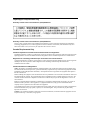
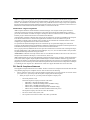
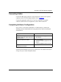
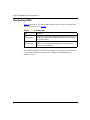
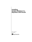
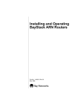
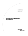
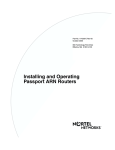
X.25 PAD Supplement
Part No. 118456-A Rev 02
November 1998
*118456-A Rev 02*
4401 Great America Parkway
Santa Clara, CA 95054
8 Federal Street
Billerica, MA 01821
Copyright © 1998 Bay Networks, Inc.
All rights reserved. Printed in the USA. November 1998.
The information in this document is subject to change without notice. The statements, configurations, technical data,
and recommendations in this document are believed to be accurate and reliable, but are presented without express or
implied warranty. Users must take full responsibility for their applications of any products specified in this document.
The information in this document is proprietary to Bay Networks, Inc.
Trademarks
Optivity, Quick2Config and Bay Networks are registered trademarks and Advanced Remote Node, ARN, BayRS,
BayStack, BCC, and the Bay Networks logo are trademarks of Bay Networks, Inc.
All other trademarks and registered trademarks are the property of their respective owners.
Statement of Conditions
In the interest of improving internal design, operational function, and/or reliability, Bay Networks, Inc. reserves the
right to make changes to the products described in this document without notice.
Bay Networks, Inc. does not assume any liability that may occur due to the use or application of the product(s) or
circuit layout(s) described herein.
USA Requirements Only
Federal Communications Commission (FCC) Compliance Notice: Radio Frequency Notice
Note: This equipment has been tested and found to comply with the limits for a Class A digital device, pursuant to
Part 15 of the FCC rules. These limits are designed to provide reasonable protection against harmful interference
when the equipment is operated in a commercial environment. This equipment generates, uses, and can radiate radio
frequency energy. If it is not installed and used in accordance with the instruction manual, it may cause harmful
interference to radio communications. Operation of this equipment in a residential area is likely to cause harmful
interference, in which case users will be required to take whatever measures may be necessary to correct the
interference at their own expense.
European Requirements Only
EN 55 022 Statement
This is to certify that the Bay Networks <product or system name> is shielded against the generation of radio
interference in accordance with the application of Council Directive 89/336/EEC, Article 4a. Conformity is declared
by the application of EN 55 022 Class A (CISPR 22).
Warning: This is a Class A product. In a domestic environment, this product may cause radio interference, in which
case, the user may be required to take appropriate measures.
EC Declaration of Conformity
This product conforms (or these products conform) to the provisions of Council Directive 89/336/EEC and
73/23/EEC. The Declaration of Conformity is available on the Bay Networks World Wide Web site at
www.baynetworks.com.
ii
118456-A Rev 02
Japan/Nippon Requirements Only
Voluntary Control Council for Interference (VCCI) Statement
Voluntary Control Council for Interference (VCCI) Statement
This is a Class A product based on the standard of the Voluntary Control Council for Interference by Information
Technology Equipment (VCCI). If this equipment is used in a domestic environment, radio disturbance may arise.
When such trouble occurs, the user may be required to take corrective actions.
Canada Requirements Only
Canadian Department of Communications Radio Interference Regulations
This digital apparatus (<product or system name>) does not exceed the Class A limits for radio-noise emissions from
digital apparatus as set out in the Radio Interference Regulations of the Canadian Department of Communications.
Règlement sur le brouillage radioélectrique du ministère des Communications
Cet appareil numérique (<product or system name>) respecte les limites de bruits radioélectriques visant les appareils
numériques de classe A prescrites dans le Règlement sur le brouillage radioélectrique du ministère des
Communications du Canada.
Canada CS-03 Rules and Regulations
Notice: The Industry Canada label identifies certified equipment. This certification means that the equipment meets
telecommunications network protective, operational and safety requirements as prescribed in the appropriate Terminal
Equipment Technical Requirements document(s). The Department does not guarantee the equipment will operate to
the user’s satisfaction.
Before installing this equipment, users should ensure that it is permissible to be connected to the facilities of the local
telecommunications company. The equipment must also be installed using an acceptable method of connection. The
customer should be aware that compliance with the above conditions may not prevent the degradation of service in
some situations.
Repairs to certified equipment should be coordinated by a representative designated by the supplier. Any repairs or
alterations made by the user to this equipment, or equipment malfunctions, may give the telecommunications
company cause to request the user to disconnect the equipment.
Users should ensure for their own protection that the electrical ground connections of the power utility, telephone lines
and internal metallic water pipe system, if present, are connected together. This precaution may be particularly
important in rural areas.
Caution: Users should not attempt to make such connections themselves, but should contact the appropriate electric
inspection authority, or electrician, as appropriate.
118456-A Rev 02
iii
Notice: For equipment using loopstart lines, please note that the Ringer Equivalence Number (REN) assigned to each
terminal device provides an indication of the maximum number of terminals allowed to be connected to a telephone
interface. The termination on an interface may consist of any combination of devices subject only to the requirement
that the sum of the Ringer Equivalence Numbers of all the devices does not exceed 5. The REN is located on the “FCC
Rules Part 68” label located on the bracket of the module, or on the back of the unit.
Canada CS-03 -- Règles et règlements
Avis: L'étiquette d'Industrie Canada identifie le matériel homologué. Cette étiquette certifie que le matériel est
conforme aux normes de protection, d'exploitation et de sécurité des réseaux de télécommunications, comme le
prescrivent les documents concernant les exigences techniques relatives au matériel terminal. Le Ministère n'assure
toutefois pas que le matériel fonctionnera à la satisfaction de l'utilisateur.
Avant d'installer ce matériel, l'utilisateur doit s'assurer qu'il est permis de le raccorder aux installations de l'entreprise
locale de télécommunication. Le matériel doit également être installé en suivant une méthode acceptée de
raccordement. L'abonné ne doit pas oublier qu'il est possible que la conformité aux conditions énoncées ci-dessus
n'empêche pas la dégradation du service dans certaines situations.
Les réparations de matériel homologué doivent être coordonnées par un représentant désigné par le fournisseur.
L'entreprise de télécommunications peut demander à l'utilisateur de débrancher un appareil à la suite de réparations ou
de modifications effectuées par l'utilisateur ou à cause de mauvais fonctionnement.
Pour sa propre protection, l'utilisateur doit s'assurer que tous les fils de mise à la terre de la source d'énergie électrique,
des lignes téléphoniques et des canalisations d'eau métalliques, s'il y en a, sont raccordés ensemble. Cette précaution
est particulièrement importante dans les régions rurales.
Avertissement: L'utilisateur ne doit pas tenter de faire ces raccordements lui-même; il doit avoir recours à un service
d'inspection des installations électriques, ou à un électricien, selon le cas.
Avis: Veuillez prendre note que pour tout appareillage supportant des lignes de type “loopstart,” l'indice d'équivalence
de la sonnerie (IES) assigné à chaque dispositif terminal indique le nombre maximal de terminaux qui peuvent être
raccordés à une interface. La terminaison d'une interface téléphonique peut consister en une combinaison de quelques
dispositifs, à la seule condition que la somme d'indices d'équivalence de la sonnerie de tous les dispositifs n'excède pas
5. Le REN figure sur l’étiquette “FCC Rules Part 68” située sur le support du module ou à l’arrière de l’unité.
FCC Part 68 Compliance Statement
This equipment complies with Part 68 of FCC Rules. All direct connections to telephone network lines must be made
using standard plugs and jacks compliant with FCC Part 68. Please note the following:
1.
You are required to request service from the telephone company before you connect the unit to a network. When
you request service, you must provide the telephone company with the following data:
•
When you request T1 Service, you must provide the telephone company with
--
The Facility Interface Code
Provide the telephone company with all the codes below:
-
04DU9-BN (1.544 MB, D4 framing format)
04DU9-DN (1.544 MB, D4 framing format with B8ZF coding)
04DU9-1KN (1.544 MB, ESF framing format)
04DU9-1SN (1.544 MB, ESF framing format with B8ZF coding)
04DU9-1ZN (1.544 MB, ANSI ESF and ZBTSI without line power)
The telephone company will select the code it has available.
iv
--
The Service Order Code(s) (SOC): 6.0F
--
The required Universal Service Order Code (USOC) jack: RJ48C
118456-A Rev 02
•
When you request 56K/64K Service, you must provide the telephone company with
--
•
The Facility Interface Code: 04DU5-56/64
--
The Service Order Code(s) (SOC): 6.0F
--
The required Universal Service Order Code (USOC) jack: RJ48S
When you request V.34 Service, you must provide the telephone company with
--
The required Universal Service Order Code (USOC) jack: RJ11C
--
The make, model number, Ringer Equivalence Number (REN), and FCC Registration number of the
unit
The REN helps you determine the number of devices you can connect to your telephone line and still have
all of those devices ring when your number is called. In most, but not all, areas, the sum of the RENs of all
devices should not exceed 5.0. To be certain of the number of devices you can connect to your line, you
should call your local telephone company to determine the maximum REN for your calling area.
This equipment must not be used on party lines or coin lines.
•
•
When you request ISDN “U” Interface Service, you must provide the telephone company with
--
The Facility Interface Code: 02IS5
--
The Service Order Code(s) (SOC): 6.0F
--
The required Universal Service Order Code (USOC) jack: RJ49C
When you request ISDN “S/T” Interface Service, you must provide the telephone company with
--
The Service Order Code(s) (SOC): 6.0N
--
The make, model number, and FCC Registration number of the NT1
Note: ISDN S/T cannot be directly connected to the network.
•
When you request Primary Rate ISDN Service, you must provide the telephone company with
--
The Facility Interface Code: 04DU9-1SN (1.544 MB, ESF framing format with B8ZF coding)
--
The Service Order Code(s) (SOC): 6.0F
--
The required Universal Service Order Code (USOC) jack: RJ48C
2.
Your telephone company may make changes to its facilities, equipment, operations, or procedures that could
affect the proper functioning of your equipment. The telephone company will notify you in advance of such
changes to give you an opportunity to maintain uninterrupted telephone service.
3.
If the unit causes harm to the telephone network, the telephone company may temporarily discontinue your
service. If possible, they will notify you in advance, but if advance notice is not practical, you will be notified as
soon as possible and will be informed of your right to file a complaint with the FCC.
4.
If you experience trouble with the unit, please contact the Bay Networks Technical Solutions Center in your area
for service or repairs. Repairs should be performed only by service personnel authorized by Bay Networks, Inc.
United States
Valbonne, France
Sydney, Australia
Tokyo, Japan
5.
1-800-2LAN-WAN
33-4-92-96-69-68
61-2-9927-8800
81-3-5402-0180
You are required to notify the telephone company when you disconnect the unit from the network.
118456-A Rev 02
v
Using the X.25 PAD Hardware Upgrade
This document supplements Installing and Operating BayStack ARN Routers,
supplied with your ARN™ router.
Follow the steps in your Installing and Operating guide (Chapter 4, “Installing a
WAN Adapter Module”), referring to this document for specific information about
the X.25 PAD upgrade. Information in this supplement includes:
•
“Verifying Router Requirements” on page 1
•
“Installing the Breakout Box” on page 2
•
“Connecting Cables” on page 3
•
“Completing Software Configuration” on page 3
•
“Interpreting LEDs” on page 4
Verifying Router Requirements
Table 1 shows the version and location of required programmable read-only
memory (PROM) code for the X.25 PAD adapter module.
Table 1.
PROM Diagnostic and Boot Code Requirements
Code Type
Minimum Version
Directory
File Name
Boot
1.18
arn_proms
arnboot.exe
Diagnostic
1.34
arn_proms
arndiag.exe
For information about upgrading PROM code, see the BayRS™ Upgrading
Routers guide.
118456-A Rev 02
1
X.25 PAD Adapter Module Supplement
Installing the Breakout Box
To support X.25 PAD applications, the ARN requires an X.25 PAD adapter
module and an attached breakout box that supplies eight additional serial ports.
Both items are part of the ARN X.25 PAD upgrade kit.
You install the X.25 PAD adapter module in one of the two ARN WAN adapter
module slots (Figure 1). See Installing and Operating BayStack ARN Routers.
X.25 PAD
TX
1
RX
COM
2
RLSD
Serial
ARN0089A
Figure 1.
X.25 PAD Adapter Module Installed in Slot 1
Position the X.25 PAD breakout box above the ARN in one of the following ways:
•
Place the box on top of the ARN (Figure 2). Attach the rubber feet that came
in the upgrade kit to the four raised areas on the bottom of the breakout box.
•
Install the box above the ARN in a standard equipment rack. Attach the
breakout box to the rack using the screws and cagenuts supplied in the
upgrade kit.
DB-25 connector ports
DB-60 cable
Tx
TX
1
RX
10BaseT
COM3
RLSD3
AUI
Rx
RLSD4
Cl
RLSD5
X.25 PAD
COM4
COM5
Serial
Ethernet 2
COM
2
Tx
RLSD
Serial
10BaseT
AUI
Run
Pwr
Boot
RPS
Adapter1
DCM
Fail
Fan
Adapter2
Base
Expansion
PCMCIA
Rx
Cl
Ethernet 1
BayStack
Advanced Remote Node
ARN0088A
Figure 2.
2
X.25 PAD Breakout Box Connected to ARN
118456-A Rev 02
Using the X.25 PAD Hardware Upgrade
Connecting Cables
Connect the DB-60 plug connector on the breakout box cable to the receptacle
connector on the X.25 PAD adapter module (refer to (Figure 2).
Connect the appropriate cables for X.25 services to the DB-25 receptacle
connectors (labeled Port #1 through Port 8) on the ARN breakout box.
Completing Software Configuration
Once you have successfully installed the X.25 PAD hardware, complete the
following software configuration tasks using instructions found in your BayRS
documentation:
Configuration Task
Location of Instructions
Modify the ARN configuration file to add the •
X.25 PAD module and enable default X.25
software services.
Configuring and Managing Routers with
Site Manager
Connect the ARN to the network.
Either of the following:
• Installing and Operating BayStack ARN
Routers
• Configuring BayStack Remote Access
Configure X.25 PAD services and breakout
box ISDB port parameters.
Configuring X.25 Services
For the latest information, be sure to review the Release Notes and Documentation
Changes for your version of BayRS software.
118456-A Rev 02
3
X.25 PAD Adapter Module Supplement
Interpreting LEDs
Table 2 describes the X.25 PAD adapter module LEDs, located to the right of the
DB-60 connector (refer to Figure 1).
Table 2.
X.25 PAD LEDs
LED
Meaning
TxD
(Transmit Data)
Lights when the X.25 PAD interface transmits data over the network.
Blinks when uploading the ISDB software image from the breakout
box to flash memory.
RxD
(Receive Data)
Lights when the X.25 PAD interface receives data from the network.
Blinks when downloading the ISDB software image from flash
memory to the breakout box.
These LEDs will blink on and off during diagnostic testing, but they will not stay
on to indicate data transfer until you have configured and enabled the X.25
software services.
4
118456-A Rev 02