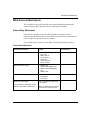
1
Part No. 308224-B Rev 00
January 2000
4401 Great America Parkway
Santa Clara, CA 95054
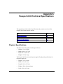
Installing and Operating the
Passport 2430 Multiservice
Access Switch
Copyright © 2000 Nortel Networks
All rights reserved. Printed in the USA. January 2000.
The information in this document is subject to change without notice. The statements, configurations, technical data,
and recommendations in this document are believed to be accurate and reliable, but are presented without express or
implied warranty. Users must take full responsibility for their applications of any products specified in this document.
The information in this document is proprietary to Nortel Networks NA Inc.
The software described in this document is furnished under a license agreement and may only be used in accordance
with the terms of that license. A summary of the Software License is included in this document.
Trademarks
NORTEL NETWORKS is a trademark of Nortel Networks.
Bay Networks is a registered trademark and Advanced Remote Node, ANH, ARN, ASN, BayRS, BCC, and Passport
are trademarks of Nortel Networks.
Microsoft, MS, MS-DOS, Win32, Windows, and Windows NT are registered trademarks of Microsoft Corporation.
All other trademarks and registered trademarks are the property of their respective owners.
Statement of Conditions
In the interest of improving internal design, operational function, and/or reliability, Nortel Networks NA Inc. reserves
the right to make changes to the products described in this document without notice.
Nortel Networks NA Inc. does not assume any liability that may occur due to the use or application of the product(s)
or circuit layout(s) described herein.
USA Requirements Only
Federal Communications Commission (FCC) Compliance Notice: Radio Frequency Notice
Note: This equipment has been tested and found to comply with the limits for a Class A digital device, pursuant to
Part 15 of the FCC rules. These limits are designed to provide reasonable protection against harmful interference
when the equipment is operated in a commercial environment. This equipment generates, uses, and can radiate radio
frequency energy. If it is not installed and used in accordance with the instruction manual, it may cause harmful
interference to radio communications. Operation of this equipment in a residential area is likely to cause harmful
interference, in which case users will be required to take whatever measures may be necessary to correct the
interference at their own expense.
European Requirements Only
EN 55 022 Statement
This is to certify that the Nortel Networks Passport 2430 Multiservice Access Switch is shielded against the
generation of radio interference in accordance with the application of Council Directive 89/336/EEC, Article 4a.
Conformity is declared by the application of EN 55 022 Class A (CISPR 22).
Warning: This is a Class A product. In a domestic environment, this product may cause radio interference, in which
case, the user may be required to take appropriate measures.
Achtung: Dieses ist ein Gerät der Funkstörgrenzwertklasse A. In Wohnbereichen können bei Betrieb dieses Gerätes
Rundfunkstörungen auftreten, in welchen Fällen der Benutzer für entsprechende Gegenmaßnahmen verantwortlich
ist.
Attention: Ceci est un produit de Classe A. Dans un environnement domestique, ce produit risque de créer des
interférences radioélectriques, il appartiendra alors à l’utilisateur de prendre les mesures spécifiques appropriées.
ii
308224-B Rev 00
To maintain compliance with FCC radio frequency emission limits, shielded cables are required to connect equipment
to other Class A certified devices and the use of quadshield, RG-6/U type CATV cable is required for connection to
the CATV system. Any changes or modifications may void the user’s authorization to operate this equipment.
EC Declaration of Conformity
This product conforms to the provisions of Council Directive 89/336/EEC and 73/23/EEC. The Declaration of
Conformity is available on the Nortel Networks World Wide Web site at
http://libra2.corpwest.baynetworks.com/cgi-bin/ndCGI.exe/DocView/.
Japan/Nippon Requirements Only
Voluntary Control Council for Interference (VCCI) Statement
Taiwan Requirements
Bureau of Standards, Metrology and Inspection (BSMI) Statement
Canada Requirements Only
Canadian Department of Communications Radio Interference Regulations
This digital apparatus (Passport 2430 Multiservice Access Switch) does not exceed the Class A limits for radio-noise
emissions from digital apparatus as set out in the Radio Interference Regulations of the Canadian Department of
Communications.
Règlement sur le brouillage radioélectrique du ministère des Communications
Cet appareil numérique (Passport 2430 Multiservice Access Switch) respecte les limites de bruits radioélectriques
visant les appareils numériques de classe A prescrites dans le Règlement sur le brouillage radioélectrique du ministère
des Communications du Canada.
308224-B Rev 00
iii
Canada CS-03 Rules and Regulations
Notice: The Industry Canada label identifies certified equipment. This certification means that the equipment meets
telecommunications network protective, operational and safety requirements as prescribed in the appropriate Terminal
Equipment Technical Requirements document(s). The Department does not guarantee the equipment will operate to
the user’s satisfaction.
Before installing this equipment, users should ensure that it is permissible to be connected to the facilities of the local
telecommunications company. The equipment must also be installed using an acceptable method of connection. The
customer should be aware that compliance with the above conditions may not prevent the degradation of service in
some situations.
Repairs to certified equipment should be coordinated by a representative designated by the supplier. Any repairs or
alterations made by the user to this equipment, or equipment malfunctions, may give the telecommunications
company cause to request the user to disconnect the equipment.
Users should ensure for their own protection that the electrical ground connections of the power utility, telephone lines
and internal metallic water pipe system, if present, are connected together. This precaution may be particularly
important in rural areas.
Caution: Users should not attempt to make such connections themselves, but should contact the appropriate electric
inspection authority, or electrician, as appropriate.
Notice: For equipment using loopstart lines, please note that the Ringer Equivalence Number (REN) assigned to each
terminal device provides an indication of the maximum number of terminals allowed to be connected to a telephone
interface. The termination on an interface may consist of any combination of devices subject only to the requirement
that the sum of the Ringer Equivalence Numbers of all the devices does not exceed 5. The REN is located on the “FCC
Rules Part 68” label located on the bracket of the module, or on the back of the unit.
Canada CS-03 -- Règles et règlements
Avis: L'étiquette d'Industrie Canada identifie le matériel homologué. Cette étiquette certifie que le matériel est
conforme aux normes de protection, d'exploitation et de sécurité des réseaux de télécommunications, comme le
prescrivent les documents concernant les exigences techniques relatives au matériel terminal. Le Ministère n'assure
toutefois pas que le matériel fonctionnera à la satisfaction de l'utilisateur.
Avant d'installer ce matériel, l'utilisateur doit s'assurer qu'il est permis de le raccorder aux installations de l'entreprise
locale de télécommunication. Le matériel doit également être installé en suivant une méthode acceptée de
raccordement. L'abonné ne doit pas oublier qu'il est possible que la conformité aux conditions énoncées ci-dessus
n'empêche pas la dégradation du service dans certaines situations.
Les réparations de matériel homologué doivent être coordonnées par un représentant désigné par le fournisseur.
L'entreprise de télécommunications peut demander à l'utilisateur de débrancher un appareil à la suite de réparations ou
de modifications effectuées par l'utilisateur ou à cause de mauvais fonctionnement.
Pour sa propre protection, l'utilisateur doit s'assurer que tous les fils de mise à la terre de la source d'énergie électrique,
des lignes téléphoniques et des canalisations d'eau métalliques, s'il y en a, sont raccordés ensemble. Cette précaution
est particulièrement importante dans les régions rurales.
Avertissement: L'utilisateur ne doit pas tenter de faire ces raccordements lui-même; il doit avoir recours à un service
d'inspection des installations électriques, ou à un électricien, selon le cas.
Avis: Veuillez prendre note que pour tout appareillage supportant des lignes de type “loopstart,” l'indice d'équivalence
de la sonnerie (IES) assigné à chaque dispositif terminal indique le nombre maximal de terminaux qui peuvent être
raccordés à une interface. La terminaison d'une interface téléphonique peut consister en une combinaison de quelques
dispositifs, à la seule condition que la somme d'indices d'équivalence de la sonnerie de tous les dispositifs n'excède pas
5. Le REN figure sur l’étiquette “FCC Rules Part 68” située sur le support du module ou à l’arrière de l’unité.
iv
308224-B Rev 00
FCC Part 68 Compliance Statement
This equipment complies with Part 68 of FCC Rules. All direct connections to telephone network lines must be made
using standard plugs and jacks compliant with FCC Part 68. Please note the following:
1.
You are required to request service from the telephone company before you connect the unit to a network. When
you request service, you must provide the telephone company with the following data:
•
When you request T1 Service, you must provide the telephone company with
--
The Facility Interface Code
Provide the telephone company with all the codes below:
-
04DU9-BN (1.544 MB, D4 framing format)
04DU9-DN (1.544 MB, D4 framing format with B8ZF coding)
04DU9-1KN (1.544 MB, ESF framing format)
04DU9-1SN (1.544 MB, ESF framing format with B8ZF coding)
04DU9-1ZN (1.544 MB, ANSI ESF and ZBTSI without line power)
The telephone company will select the code it has available.
•
•
--
The Service Order Code(s) (SOC): 6.0F
--
The required Universal Service Order Code (USOC) jack: RJ48C
When you request 56K/64K Service, you must provide the telephone company with
--
The Facility Interface Code: 04DU5-56/64
--
The Service Order Code(s) (SOC): 6.0F
--
The required Universal Service Order Code (USOC) jack: RJ48S
When you request V.34 Service, you must provide the telephone company with
--
The required Universal Service Order Code (USOC) jack: RJ11C
--
The make, model number, Ringer Equivalence Number (REN), and FCC Registration number of the
unit
The REN helps you determine the number of devices you can connect to your telephone line and still have
all of those devices ring when your number is called. In most, but not all, areas, the sum of the RENs of all
devices should not exceed 5.0. To be certain of the number of devices you can connect to your line, you
should call your local telephone company to determine the maximum REN for your calling area. This
equipment must not be used on party lines or coin lines.
•
When you request ISDN “U” Interface Service, you must provide the telephone company with
--
•
The Facility Interface Code: 02IS5
--
The Service Order Code(s) (SOC): 6.0F
--
The required Universal Service Order Code (USOC) jack: RJ49C
When you request ISDN “S/T” Interface Service, you must provide the telephone company with
--
The Service Order Code(s) (SOC): 6.0N
--
The make, model number, and FCC Registration number of the NT1
Note: ISDN S/T cannot be directly connected to the network.
308224-B Rev 00
v
•
When you request Primary Rate ISDN Service, you must provide the telephone company with
--
The Facility Interface Code: 04DU9-1SN (1.544 MB, ESF framing format with B8ZF coding)
--
The Service Order Code(s) (SOC): 6.0F
--
The required Universal Service Order Code (USOC) jack: RJ48C
2.
Your telephone company may make changes to its facilities, equipment, operations, or procedures that could
affect the proper functioning of your equipment. The telephone company will notify you in advance of such
changes to give you an opportunity to maintain uninterrupted telephone service.
3.
If the unit causes harm to the telephone network, the telephone company may temporarily discontinue your
service. If possible, they will notify you in advance, but if advance notice is not practical, you will be notified
as soon as possible and will be informed of your right to file a complaint with the FCC.
4.
If you experience trouble with the unit, please contact the Nortel Networks Technical Solutions Center in
your area for service or repairs. Repairs should be performed only by service personnel authorized by
Nortel Networks.
United States
Valbonne, France
Sydney, Australia
Tokyo, Japan
5.
1-800-2LANWAN
33-4-92-96-69-68
61-2-9927-8800
81-3-5740-1700
You are required to notify the telephone company when you disconnect the unit from the network.
Nortel Networks NA Inc. Software License Agreement
NOTICE: Please carefully read this license agreement before copying or using the accompanying software or
installing the hardware unit with pre-enabled software (each of which is referred to as “Software” in this Agreement).
BY COPYING OR USING THE SOFTWARE, YOU ACCEPT ALL OF THE TERMS AND CONDITIONS OF
THIS LICENSE AGREEMENT. THE TERMS EXPRESSED IN THIS AGREEMENT ARE THE ONLY TERMS
UNDER WHICH NORTEL NETWORKS WILL PERMIT YOU TO USE THE SOFTWARE. If you do not accept
these terms and conditions, return the product, unused and in the original shipping container, within 30 days of
purchase to obtain a credit for the full purchase price.
1. License Grant. Nortel Networks NA Inc. (“Nortel Networks”) grants the end user of the Software (“Licensee”) a
personal, nonexclusive, nontransferable license: a) to use the Software either on a single computer or, if applicable, on
a single authorized device identified by host ID, for which it was originally acquired; b) to copy the Software solely
for backup purposes in support of authorized use of the Software; and c) to use and copy the associated user manual
solely in support of authorized use of the Software by Licensee. This license applies to the Software only and does not
extend to Nortel Networks Agent software or other Nortel Networks software products. Nortel Networks Agent
software or other Nortel Networks software products are licensed for use under the terms of the applicable Nortel
Networks NA Inc. Software License Agreement that accompanies such software and upon payment by the end user of
the applicable license fees for such software.
2. Restrictions on use; reservation of rights. The Software and user manuals are protected under copyright laws.
Nortel Networks and/or its licensors retain all title and ownership in both the Software and user manuals, including
any revisions made by Nortel Networks or its licensors. The copyright notice must be reproduced and included with
any copy of any portion of the Software or user manuals. Licensee may not modify, translate, decompile, disassemble,
use for any competitive analysis, reverse engineer, distribute, or create derivative works from the Software or user
manuals or any copy, in whole or in part. Except as expressly provided in this Agreement, Licensee may not copy or
transfer the Software or user manuals, in whole or in part. The Software and user manuals embody Nortel Networks’
and its licensors’ confidential and proprietary intellectual property. Licensee shall not sublicense, assign, or otherwise
disclose to any third party the Software, or any information about the operation, design, performance, or
implementation of the Software and user manuals that is confidential to Nortel Networks and its licensors; however,
Licensee may grant permission to its consultants, subcontractors, and agents to use the Software at Licensee’s facility,
provided they have agreed to use the Software only in accordance with the terms of this license.
vi
308224-B Rev 00
3. Limited warranty. Nortel Networks warrants each item of Software, as delivered by Nortel Networks and properly
installed and operated on Nortel Networks hardware or other equipment it is originally licensed for, to function
substantially as described in its accompanying user manual during its warranty period, which begins on the date
Software is first shipped to Licensee. If any item of Software fails to so function during its warranty period, as the sole
remedy Nortel Networks will at its discretion provide a suitable fix, patch, or workaround for the problem that may be
included in a future Software release. Nortel Networks further warrants to Licensee that the media on which the
Software is provided will be free from defects in materials and workmanship under normal use for a period of 90 days
from the date Software is first shipped to Licensee. Nortel Networks will replace defective media at no charge if it is
returned to Nortel Networks during the warranty period along with proof of the date of shipment. This warranty does
not apply if the media has been damaged as a result of accident, misuse, or abuse. The Licensee assumes all
responsibility for selection of the Software to achieve Licensee’s intended results and for the installation, use, and
results obtained from the Software. Nortel Networks does not warrant a) that the functions contained in the software
will meet the Licensee’s requirements, b) that the Software will operate in the hardware or software combinations that
the Licensee may select, c) that the operation of the Software will be uninterrupted or error free, or d) that all defects
in the operation of the Software will be corrected. Nortel Networks is not obligated to remedy any Software defect that
cannot be reproduced with the latest Software release. These warranties do not apply to the Software if it has been (i)
altered, except by Nortel Networks or in accordance with its instructions; (ii) used in conjunction with another
vendor’s product, resulting in the defect; or (iii) damaged by improper environment, abuse, misuse, accident, or
negligence. THE FOREGOING WARRANTIES AND LIMITATIONS ARE EXCLUSIVE REMEDIES AND ARE
IN LIEU OF ALL OTHER WARRANTIES EXPRESS OR IMPLIED, INCLUDING WITHOUT LIMITATION ANY
WARRANTY OF MERCHANTABILITY OR FITNESS FOR A PARTICULAR PURPOSE. Licensee is responsible
for the security of its own data and information and for maintaining adequate procedures apart from the Software to
reconstruct lost or altered files, data, or programs.
4. Limitation of liability. IN NO EVENT WILL NORTEL NETWORKS OR ITS LICENSORS BE LIABLE FOR
ANY COST OF SUBSTITUTE PROCUREMENT; SPECIAL, INDIRECT, INCIDENTAL, OR CONSEQUENTIAL
DAMAGES; OR ANY DAMAGES RESULTING FROM INACCURATE OR LOST DATA OR LOSS OF USE OR
PROFITS ARISING OUT OF OR IN CONNECTION WITH THE PERFORMANCE OF THE SOFTWARE, EVEN
IF NORTEL NETWORKS HAS BEEN ADVISED OF THE POSSIBILITY OF SUCH DAMAGES. IN NO EVENT
SHALL THE LIABILITY OF NORTEL NETWORKS RELATING TO THE SOFTWARE OR THIS AGREEMENT
EXCEED THE PRICE PAID TO NORTEL NETWORKS FOR THE SOFTWARE LICENSE.
5. Government Licensees. This provision applies to all Software and documentation acquired directly or indirectly by
or on behalf of the United States Government. The Software and documentation are commercial products, licensed on
the open market at market prices, and were developed entirely at private expense and without the use of any U.S.
Government funds. The license to the U.S. Government is granted only with restricted rights, and use, duplication, or
disclosure by the U.S. Government is subject to the restrictions set forth in subparagraph (c)(1) of the Commercial
Computer Software––Restricted Rights clause of FAR 52.227-19 and the limitations set out in this license for civilian
agencies, and subparagraph (c)(1)(ii) of the Rights in Technical Data and Computer Software clause of DFARS
252.227-7013, for agencies of the Department of Defense or their successors, whichever is applicable.
6. Use of Software in the European Community. This provision applies to all Software acquired for use within the
European Community. If Licensee uses the Software within a country in the European Community, the Software
Directive enacted by the Council of European Communities Directive dated 14 May, 1991, will apply to the
examination of the Software to facilitate interoperability. Licensee agrees to notify Nortel Networks of any such
intended examination of the Software and may procure support and assistance from Nortel Networks.
308224-B Rev 00
vii
7. Term and termination. This license is effective until terminated; however, all of the restrictions with respect to
Nortel Networks’ copyright in the Software and user manuals will cease being effective at the date of expiration of the
Nortel Networks copyright; those restrictions relating to use and disclosure of Nortel Networks’ confidential
information shall continue in effect. Licensee may terminate this license at any time. The license will automatically
terminate if Licensee fails to comply with any of the terms and conditions of the license. Upon termination for any
reason, Licensee will immediately destroy or return to Nortel Networks the Software, user manuals, and all copies.
Nortel Networks is not liable to Licensee for damages in any form solely by reason of the termination of this license.
8. Export and Re-export. Licensee agrees not to export, directly or indirectly, the Software or related technical data
or information without first obtaining any required export licenses or other governmental approvals. Without limiting
the foregoing, Licensee, on behalf of itself and its subsidiaries and affiliates, agrees that it will not, without first
obtaining all export licenses and approvals required by the U.S. Government: (i) export, re-export, transfer, or divert
any such Software or technical data, or any direct product thereof, to any country to which such exports or re-exports
are restricted or embargoed under United States export control laws and regulations, or to any national or resident of
such restricted or embargoed countries; or (ii) provide the Software or related technical data or information to any
military end user or for any military end use, including the design, development, or production of any chemical,
nuclear, or biological weapons.
9. General. If any provision of this Agreement is held to be invalid or unenforceable by a court of competent
jurisdiction, the remainder of the provisions of this Agreement shall remain in full force and effect. This Agreement
will be governed by the laws of the state of California.
Should you have any questions concerning this Agreement, contact Nortel Networks, 4401 Great America Parkway,
P.O. Box 58185, Santa Clara, California 95054-8185.
LICENSEE ACKNOWLEDGES THAT LICENSEE HAS READ THIS AGREEMENT, UNDERSTANDS IT, AND
AGREES TO BE BOUND BY ITS TERMS AND CONDITIONS. LICENSEE FURTHER AGREES THAT THIS
AGREEMENT IS THE ENTIRE AND EXCLUSIVE AGREEMENT BETWEEN NORTEL NETWORKS AND
LICENSEE, WHICH SUPERSEDES ALL PRIOR ORAL AND WRITTEN AGREEMENTS AND
COMMUNICATIONS BETWEEN THE PARTIES PERTAINING TO THE SUBJECT MATTER OF THIS
AGREEMENT. NO DIFFERENT OR ADDITIONAL TERMS WILL BE ENFORCEABLE AGAINST NORTEL
NETWORKS UNLESS NORTEL NETWORKS GIVES ITS EXPRESS WRITTEN CONSENT, INCLUDING AN
EXPRESS WAIVER OF THE TERMS OF THIS AGREEMENT.
viii
308224-B Rev 00
Contents
Preface
Before You Begin .............................................................................................................xix
Text Conventions ............................................................................................................. xx
Acronyms .........................................................................................................................xxi
Hard-Copy Technical Manuals ........................................................................................xxii
How to Get Help ............................................................................................................ xxiii
Chapter 1
Installing the Passport 2430 Chassis
The Passport 2430 .........................................................................................................1-2
Preparing to Install the Passport 2430 ...........................................................................1-3
Verifying Shipment Contents ....................................................................................1-3
Wall Mount Kit ....................................................................................................1-5
Shelf Kit .............................................................................................................1-6
Additional Equipment ...............................................................................................1-8
Tools ..................................................................................................................1-8
Cables ................................................................................................................1-8
Management Console .......................................................................................1-8
Verifying Site Requirements ...........................................................................................1-9
Installing the Passport 2430 on a Flat Surface ........................................................1-9
Wall-Mounting the Passport 2430 .................................................................................1-10
Hanging the Wall Bracket .......................................................................................1-10
Hanging the Passport 2430 ....................................................................................1-13
Mounting the Passport 2430 in an Equipment Rack ....................................................1-15
Installing a Shelf in an Equipment Rack .................................................................1-15
Installing the Passport 2430 on the Shelf ...............................................................1-18
Connecting to the LAN .................................................................................................1-20
308224-B Rev 00
ix
Connecting a Management Console ............................................................................1-20
Connecting a PC Console ......................................................................................1-20
Connecting a Terminal Console .............................................................................1-22
Connecting the External Power Supply ........................................................................1-24
Where to Go Next .........................................................................................................1-25
Chapter 2
Installing Passport 2430 Components
PCMCIA Flash Memory Card .........................................................................................2-1
Installing the Flash Memory Card ............................................................................2-2
PCMCIA Modem Card ....................................................................................................2-3
Installing a Modem Card ..........................................................................................2-4
WAN Adapter Module .....................................................................................................2-6
Installing a WAN Adapter Module ............................................................................2-7
Where to Go Next .........................................................................................................2-11
Chapter 3
Starting the Passport 2430 for the First Time
Understanding the Startup Process ...............................................................................3-1
Starting the Passport 2430 .............................................................................................3-2
Accessing a Command-Line Interface .....................................................................3-3
Running the Quick-Start Script ................................................................................3-3
Where to Go Next ...........................................................................................................3-6
Chapter 4
Operating the Passport 2430
Understanding the LEDs ................................................................................................4-1
Passport 2430 LEDs ................................................................................................4-2
LED on the Front of the Passport 2430 ....................................................................4-2
LEDs on the Back of the Passport 2430 ..................................................................4-2
Diagnostic LEDs .......................................................................................................4-3
LAN Interface LEDs .................................................................................................4-4
Verifying a Successful Installation ..................................................................................4-4
Diagnostic Software ........................................................................................................4-5
Enabling and Disabling Diagnostic Software ............................................................4-7
x
308224-B Rev 00
Turning the Power On and Off ........................................................................................4-8
Replacing a Flash Memory Card ....................................................................................4-9
Protecting Flash Memory Card Files ............................................................................4-11
Securing the Passport 2430 .........................................................................................4-12
Chapter 5
Adding and Replacing a WAN Adapter Module
Downloading New Boot and Diagnostic Code ................................................................5-1
Preparing to Install the WAN Adapter Module ................................................................5-2
Removing the Filler Panel ........................................................................................5-4
Removing a WAN Adapter Module ..........................................................................5-5
Installing a WAN Adapter Module ...................................................................................5-6
Chapter 6
Replacing a PCMCIA Modem Card
Removing a Modem Card ...............................................................................................6-2
Installing a Modem Card .................................................................................................6-3
Modem Card Support .....................................................................................................6-5
Chapter 7
Upgrading Memory
Installing the SIMM .........................................................................................................7-1
Turn Off the Passport 2430 ......................................................................................7-2
Remove the Cover from the Chassis .......................................................................7-3
Removing a SIMM ....................................................................................................7-5
Inserting a SIMM ......................................................................................................7-6
Replacing the Chassis Cover ...................................................................................7-7
Starting the Passport 2430 ......................................................................................7-7
Appendix A
Passport 2430 Technical Specifications
Physical Specifications .................................................................................................. A-1
Electrical Specifications ................................................................................................. A-3
Environmental Specifications ........................................................................................ A-3
Hardware Communications Options .............................................................................. A-4
Ethernet 10/100BASE-TX Interface ........................................................................ A-5
Serial Interfaces ............................................................................................................. A-6
308224-B Rev 00
xi
Appendix B
Quick-Start Worksheets
Understanding Quick-Start Connector Names and Numbers ........................................ B-2
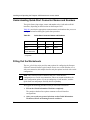
Filling Out the Worksheets ............................................................................................ B-2
Global Information Worksheet ....................................................................................... B-3
Router Protocol Worksheets .......................................................................................... B-5
RIP Worksheet ........................................................................................................ B-6
OSPF Worksheet .................................................................................................... B-7
Static Route Worksheet ........................................................................................ B-10
WAN Protocol Worksheets .......................................................................................... B-11
Frame Relay Worksheet ........................................................................................ B-11
PPP Standard Worksheet ..................................................................................... B-12
Nortel Networks Proprietary PPP Worksheet ....................................................... B-14
SMDS Worksheet .................................................................................................. B-15
Index
xii
308224-B Rev 00
Figures
Figure 1-1.
Passport 2430 with Components Installed ...............................................1-2
Figure 1-2.
Items in the Passport 2430 Shipping Container .......................................1-4
Figure 1-3.
Items in the Wall Mount Kit Shipping Container .......................................1-5
Figure 1-4.
Items in the Shelf Kit ................................................................................1-7
Figure 1-5.
Wall Bracket ...........................................................................................1-10
Figure 1-6.
Leveling the Wall Bracket .......................................................................1-11
Figure 1-7.
Attaching the Wall Bracket .....................................................................1-12
Figure 1-8.
Mounting Slots on the Passport 2430 ....................................................1-13
Figure 1-9.
Aligning the Mounting Slots ...................................................................1-14
Figure 1-10. Positioning the Shelf and the Bracket ....................................................1-15
Figure 1-11. Assembling the Shelf Unit ......................................................................1-16
Figure 1-12. Installing the Shelf Unit into the Equipment Rack ..................................1-17
Figure 1-13. Positioning the Passport 2430 ...............................................................1-18
Figure 1-14. Installing the Passport 2430 onto a Shelf ..............................................1-19
Figure 1-15. Connecting to the LAN ...........................................................................1-20
Figure 1-16. Passport 2430 Console Port ..................................................................1-21
Figure 1-17. Connecting a Laptop PC to a Passport 2430 .........................................1-22
Figure 1-18. Connecting a Terminal Console to a Passport 2430 ..............................1-23
Figure 1-19. External Power Supply ...........................................................................1-24
Figure 1-20. Connecting the Power Supply to the Passport 2430 ..............................1-25
Figure 2-1.
PCMCIA Flash Memory Card ..................................................................2-1
Figure 2-2.
Inserting the Flash Memory Card ............................................................2-2
Figure 2-3.
Xircom RealPort Modem Card .................................................................2-3
Figure 2-4.
Inserting the Modem Card .......................................................................2-4
Figure 2-5.
Connecting the Telephone Line to the Modem Card ................................2-5
Figure 2-6.
WAN Adapter Module ..............................................................................2-6
Figure 2-7.
Location of Adapter Module 1 and 2 Slots ...............................................2-7
Figure 2-8.
Connecting the Wrist Strap Jack to the Metal Tab on a
WAN Adapter Module ..............................................................................2-8
308224-B Rev 00
xiii
Figure 2-9.
Removing the Filler Panel from the 2 WAN Adapter Module Slot ............2-9
Figure 2-10. WAN Adapter Module Ready for Installation ..........................................2-10
Figure 2-11. Inserting the WAN Adapter Module .......................................................2-10
Figure 2-12. Securing the WAN Adapter Module to the Front Panel ..........................2-11
Figure 3-1.
Starting the IP Interface Test ....................................................................3-5
Figure 4-1.
LED Located on the Front of the Passport 2430 ......................................4-2
Figure 4-2.
LEDs Located on the Back Panel of the Passport 2430 ..........................4-2
Figure 4-3.
Diagnostic LEDs ......................................................................................4-3
Figure 4-4.
LAN Port and Interface LEDs ...................................................................4-4
Figure 4-5.
Diagnostic LEDs ......................................................................................4-4
Figure 4-6.
Power Switch ...........................................................................................4-8
Figure 4-7.
Ejecting a Passport 2430 Flash Memory Card ........................................4-9
Figure 4-8.
Inserting the Flash Memory Card ..........................................................4-10
Figure 4-9.
Flash Memory Card Read/Write Protect Switch ....................................4-11
Figure 4-10. Security Slot ...........................................................................................4-12
xiv
Figure 5-1.
Connecting the Wrist Strap Jack to the Metal Tab on a
WAN Adapter Module ..............................................................................5-3
Figure 5-2.
Location of the WAN Adapter Module 1 and 2 Slots ................................5-3
Figure 5-3.
Removing the Filler Panel from the 2 Slot ................................................5-4
Figure 5-4.
Removing the WAN Adapter Module Screw ............................................5-5
Figure 5-5.
WAN Adapter Module Ready for Installation ............................................5-6
Figure 5-6.
Inserting the WAN Adapter Module .........................................................5-6
Figure 5-7.
Securing the WAN Adapter Module to the Back Panel ............................5-7
Figure 6-1.
Xircom RealPort Modem Card .................................................................6-1
Figure 6-2.
Removing a Passport 2430 Modem Card ................................................6-2
Figure 6-3.
Inserting the Modem Card .......................................................................6-3
Figure 6-4.
Connecting the Telephone Line to the Modem Card ................................6-4
Figure 7-1.
Power Switch ...........................................................................................7-2
Figure 7-2.
Removing the Screws from the Passport 2430 ........................................7-3
Figure 7-3.
Removing the Chassis Cover ...................................................................7-4
Figure 7-4.
Location of the SIMM Slot ........................................................................7-4
Figure 7-5.
Pull the Tabs on Either Side of the SIMM ................................................7-5
Figure 7-6.
Position and Insert the SIMM (1), then Push the SIMM Down (2) ...........7-6
Figure 7-7.
Replacing the Chassis Cover ...................................................................7-7
308224-B Rev 00
Tables
Table 1-1.
PC Console Parameters ........................................................................1-21
Table 1-2.
Terminal Console Parameters ................................................................1-22
Table 2-1.
Modem Defaults .......................................................................................2-6
Table 3-1.
Quick-Start Commands ...........................................................................3-4
Table 4-1.
Base Module Diagnostic LEDs ................................................................4-3
Table 4-2.
Diagnostic Testing ....................................................................................4-6
Table 6-1.
Modem Defaults .......................................................................................6-5
Table A-1.
Passport 2430 Power Outlet Requirements ............................................ A-3
Table A-2.
Network Interfaces Available on the Passport 2430 ................................ A-4
Table A-3.
10/100BASE-TX Interface Pin Assignments ........................................... A-5
Table A-4.
Local Console Port RJ-45 Pin Assignments ........................................... A-6
Table B-1.
Quick-Start Connector Names and Numbers ......................................... B-2
308224-B Rev 00
xv
Preface
The Passport™ 2430 mutliservice access switch, which provides a LAN
connection and two slots for WAN adapter modules, supports a broad array of
primary and backup connectivity options. This guide describes how to install,
start, and operate the Passport 2430.
Before You Begin
This guide is intended for qualified personnel who are installing the Passport 2430
for the first time or who need to add or replace the flash memory card, WAN
adapter module, or the PCMCIA modem card. A qualified person should be
familiar with computer systems, computer ports, and network protocols.
Before installing the Passport 2430, ensure that all network wiring has been
installed on the premises using standard cable-system practices.
Before turning on the Passport 2430 for the first time, contact your network
administrator to determine which software configuration option to use.
308224-B Rev 00
xvii
Installing and Operating the Passport 2430 Multiservice Access Switch
Text Conventions
This guide uses the following text conventions:
angle brackets (< >)
Indicate that you choose the text to enter based on the
description inside the brackets. Do not type the
brackets when entering the command.
Example: If the command syntax is:
ping <ip_address>, you enter:
ping 192.32.10.12
bold text
Indicates command names and options and text that
you need to enter.
Example: Enter show ip {alerts | routes}.
Example: Use the dinfo command.
braces ({})
Indicate required elements in syntax descriptions
where there is more than one option. You must choose
only one of the options. Do not type the braces when
entering the command.
Example: If the command syntax is:
show ip {alerts | routes}, you must enter either:
show ip alerts or show ip routes, but not both.
brackets ([ ])
Indicate optional elements in syntax descriptions. Do
not type the brackets when entering the command.
Example: If the command syntax is:
show ip interfaces [-alerts], you can enter either:
show ip interfaces or show ip interfaces -alerts.
xviii
308224-B Rev 00
Preface
italic text
Indicates file and directory names, new terms, book
titles, and variables in command syntax descriptions.
Where a variable is two or more words, the words are
connected by an underscore.
Example: If the command syntax is:
show at <valid_route>
valid_route is one variable and you substitute one value
for it.
screen text
Indicates system output, for example, prompts and
system messages.
Example: Set Bay Networks Trap Monitor Filters
Acronyms
308224-B Rev 00
ANSI
American National Standards Institute
ARP
Address Resolution Protocol
AUI
attachment unit interface
BRI
basic rate interface
CHAP
Challenge Handshake Authentication Protocol
CSU
channel service unit
CTS
clear to send
DCE
data communication equipment
DSU
data service unit
DTE
data terminal equipment
DTR
data terminal ready
EIA
Electronic Industries Association
FTP
File Transfer Protocol
IEEE
Institute of Electrical and Electronic Engineers
IP
Internet Protocol
ISDN
Integrated Services Digital Network
xix
Installing and Operating the Passport 2430 Multiservice Access Switch
ITU-T
International Telecommunication
Union-Telecommunications
LAN
local area network
LED
light emitting diode
LQR
Link Quality Report
NBMA
nonbroadcast multi-access
NEMA
National Electrical Manufacturers Association
NVFS
nonvolatile file system
OSPF
Open Shortest Path First
PAP
Password Authentication Protocol
PCMCIA
Personal Computer Memory Card International
Association
PPP
Point-to-Point Protocol
PROM
programmable read-only memory
RIP
Routing Information Protocol
SMDS
Switched Multi Megabit Data Service
TFTP
Trivial File Transfer Protocol
WAN
wide area network
Hard-Copy Technical Manuals
You can print selected technical manuals and release notes free, directly from the
Internet. Go to support.baynetworks.com/library/tpubs/. Find the product for
which you need documentation. Then locate the specific category and model or
version for your hardware or software product. Using Adobe Acrobat Reader, you
can open the manuals and release notes, search for the sections you need, and print
them on most standard printers. You can download Acrobat Reader free from the
Adobe Systems Web site, www.adobe.com.
xx
308224-B Rev 00
Preface
You can purchase selected documentation sets, CDs, and technical publications
through the collateral catalog. The catalog is located on the World Wide Web at
support.baynetworks.com/catalog.html and is divided into sections arranged
alphabetically:
•
The “CD ROMs” section lists available CDs.
•
The “Guides/Books” section lists books on technical topics.
•
The “Technical Manuals” section lists available printed documentation sets.
How to Get Help
If you purchased a service contract for your Nortel Networks™ product from a
distributor or authorized reseller, contact the technical support staff for that
distributor or reseller for assistance.
If you purchased a Nortel Networks service program, contact one of the following
Nortel Networks Technical Solutions Centers:
308224-B Rev 00
Technical Solutions Center
Telephone Number
Billerica, MA
800-2LANWAN (800-252-6926)
Santa Clara, CA
800-2LANWAN (800-252-6926)
Valbonne, France
33-4-92-96-69-68
Sydney, Australia
61-2-9927-8800
Tokyo, Japan
81-3-5740-1745
xxi
Chapter 1
Installing the Passport 2430 Chassis
This chapter describes how to install the Passport 2430 router.
Topic
Page
The Passport 2430
1-2
Preparing to Install the Passport 2430
1-3
Installing the Passport 2430 on a Flat Surface
1-9
Wall-Mounting the Passport 2430
1-10
Mounting the Passport 2430 in an Equipment Rack
1-15
Connecting to the LAN
1-20
Connecting a Management Console
1-20
Connecting the External Power Supply
1-24
Where to Go Next
1-25
Note: The installation instructions in this chapter assume that wiring is
already installed on the premises using common cable system practices. Your
installation procedure may differ slightly, depending on your cable system.
308224-B Rev 00
1-1
Installing and Operating the Passport 2430 Multiservice Access Switch
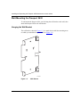
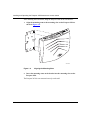
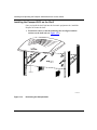
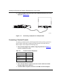
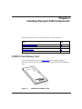
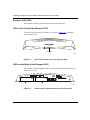
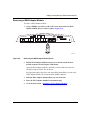
The Passport 2430
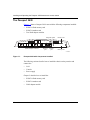
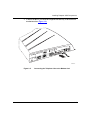
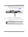
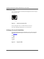
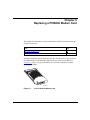
Figure 1-1 shows a Passport 2430 router with the following components installed:
•
PCMCIA flash memory card
•
PCMCIA modem card
•
Two WAN adapter modules
Diagnostic LEDs
Modem card
Passport 2430
1
2
10/100
Console
Modem
l
Run
2
Boot
Link
WAN adapter modues
TX/RX
Ethernet
port
1
Fail
Flash
Console
port
PCMCIA
O
Power port
Memory card
VLK0001A
Figure 1-1.
Passport 2430 with Components Installed
The following sections describe how to install the chassis on the premises and
connect the:
•
LAN
•
Console
•
Power supply
Chapter 2 describes how to install the:
1-2
•
PCMCIA flash memory card
•
PCMCIA modem card
•
WAN adapter module
308224-B Rev 00
Installing the Passport 2430 Chassis
Preparing to Install the Passport 2430
Verify the following before beginning the installation, as explained in the sections
that follow:
•
•
•
•
Your shipment is complete and undamaged.
You have the proper equipment and tools.
Your installation site meets physical, electrical, and environmental
requirements (see Appendix A, “Passport 2430 Technical Specifications”).
You have the cabling that you need to attach to the Passport 2430.
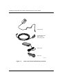
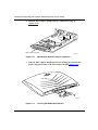
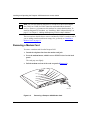
Verifying Shipment Contents
You should inspect all items for shipping damage. If you detect any damage, do
not install the Passport 2430. Call the Nortel Networks Technical Solutions Center
in your area, as described in “How to Get Help” on page xxi.
In addition to the Passport 2430 and this guide, your shipping container should
contain several other items. Verify that the items in the shipping container match
those on the packing list affixed to the shipping container.
Refer to the following checklist and to Figure 1-2 to verify the contents of the
shipping container:
308224-B Rev 00
_
Antistatic wrist strap
_
Power supply for Passport 2430
_
One power cord
_
One RJ-45 to DB-9 cable
1-3
Installing and Operating the Passport 2430 Multiservice Access Switch
ESD wrist strap
Console/modem cable
(DB-9 receptacle
to RJ-45 plug cable)
Power supply
Power cord
VLK0006A
Figure 1-2.
1-4
Items in the Passport 2430 Shipping Container
308224-B Rev 00
Installing the Passport 2430 Chassis
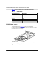
Wall Mount Kit
If you are mounting the Passport 2430 on a wall, you need a wall mount kit (Order
No. PB0011001).
Once you have the wall mount kit, refer to the following checklist and to
Figure 1-2 to verify the contents of the wall mount kit shipping container:
_
Wall bracket
_
Two #10 three-quarter-inch self-drilling, tapping Phillips pan head screws
VLK0040A
Figure 1-3.
308224-B Rev 00
Items in the Wall Mount Kit Shipping Container
1-5
Installing and Operating the Passport 2430 Multiservice Access Switch
Shelf Kit
If you are mounting the Passport 2430 on a rack, you will need a shelf kit (Order
No. PB0011002).
Once you have the shelf kit, refer to the following checklist and to Figure 1-4 to
verify the contents of the shelf kit shipping container:
1-6
_
One shelf
_
Two brackets
_
Two #2 one-quarter-inch screws
_
Four cage nuts
_
Four cagenut screws and washers
308224-B Rev 00
Installing the Passport 2430 Chassis
One shelf
Two brackets
Two #2 screws
Four cage nuts
Four #10 cagenut
screws and washers
VLK0045A
Figure 1-4.
308224-B Rev 00
Items in the Shelf Kit
1-7
Installing and Operating the Passport 2430 Multiservice Access Switch
Additional Equipment
Before installing the Passport 2430 hardware, ensure that you obtain all the
cables, tools, and other equipment that you need.
Tools
To install a WAN adapter you need a Phillips screwdriver to remove the filler
panel.
To wall-mount the Passport 2430, you need the following tools:
•
Phillips screwdriver
•
Carpenter’s level
To rack-mount the Passport 2430, you need a Phillips screwdriver to assemble the
shelf unit and attach the shelf unit to an equipment rack.
Cables
Unless they were specifically ordered, the cables necessary for your network
configuration are not part of the Passport 2430 accessory package. If you do not
have the proper cables, contact your network administrator or see the Cable
Guide.
Management Console
Before you boot the Passport 2430 for the first time, you need to attach a terminal
or PC to the Passport 2430 to monitor the results of startup diagnostics and
perform manual boot configurations. If you use a terminal as your management
console, you need a DB-9 to DB-25 adapter to connect the router to the terminal.
After the initial start-up, you can use the PCMCIA modem for remote dial-in
access to the Passport 2430.
1-8
308224-B Rev 00
Installing the Passport 2430 Chassis
Verifying Site Requirements
The installation site must provide 2 inches (in.) (5.1 cm) of free space above the
Passport 2430 to dissipate heat.
If you are rack mounting the Passport 2430, the equipment rack should meet the
following specifications:
•
•
•
•
Heavy-duty steel construction
Electronic Industries Association (EIA) standard hole-spacing
Width of 19 in. (48 cm)
Depth of 24 in. (61 cm)
In addition, the installation site must meet the electrical and environmental
specifications listed in Appendix A, “Passport 2430 Technical Specifications.”
Caution: You must use grounded electrical power outlets with the Passport
2430 power source.
Installing the Passport 2430 on a Flat Surface
When you are ready to install the Passport 2430, position the router on a flat,
sturdy, horizontal surface that provides:
308224-B Rev 00
•
2 in. (5 cm) clearance above the chassis for heat dissipation.
•
Support for the combined weight of the Passport 2430, the power supply, the
power cord, the LAN cable, and any WAN cables that you connect.
1-9
Installing and Operating the Passport 2430 Multiservice Access Switch
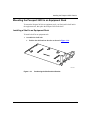
Wall-Mounting the Passport 2430
To wall-mount the Passport 2430, you first hang the wall bracket on the wall, then
attach the Passport 2430 to the wall bracket.
Hanging the Wall Bracket
The wall bracket, shown in Figure 1-5, is a metal device with four mounting arms
on which you attach the Passport 2430 (see Figure 1-5).
VLK0040A
Figure 1-5.
1-10
Wall Bracket
308224-B Rev 00
Installing the Passport 2430 Chassis
To hang the wall bracket on a wall:
1.
Determine the location you want to hang the wall bracket.
2.
Level the wall bracket:
a.
Hold the bracket against the wall.
b.
Put the carpenter’s level on the bracket arms as shown in Figure 1-6.
c.
Watching the carpenter’s level, adjust the wall bracket until it is level.
VLK0042A
Figure 1-6.
308224-B Rev 00
Leveling the Wall Bracket
1-11
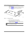
Installing and Operating the Passport 2430 Multiservice Access Switch
3.
Screw the bracket onto the wall using the 3/4 in. self-drilling pan head
screws and the Phillips screwdriver (see Figure 1-7).
VLK0043A
Figure 1-7.
1-12
Attaching the Wall Bracket
308224-B Rev 00
Installing the Passport 2430 Chassis
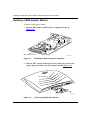
Hanging the Passport 2430
The Passport 2430 has two mounting slots and two vents located on the bottom of
the router (see Figure 1-8) that match up to the four mounting arms on the wall
bracket.
Vents
ATTACH WALL MOUNT BRACKET HERE
Passport 2430
M/N
S/N
P/N
Mounting slots
VLK0041A
Figure 1-8.
308224-B Rev 00
Mounting Slots on the Passport 2430
1-13
Installing and Operating the Passport 2430 Multiservice Access Switch
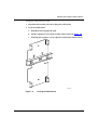
After installing the wall bracket, hang the Passport 2430 on the wall bracket:
1.
Align the mounting arms to the mounting slots on the Passport 2430 as
shown in Figure 1-9.
PMCIA
Fail
Boot
Run
Passp
ort 24
30
VLK0044A
Figure 1-9.
2.
Aligning the Mounting Slots
Insert the mounting arms on the bracket into the mounting slots on the
Passport 2430.
The Passport 2430 is now mounted securely on the wall.
1-14
308224-B Rev 00
Installing the Passport 2430 Chassis
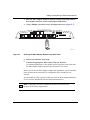
Mounting the Passport 2430 in an Equipment Rack
To mount the Passport 2430 in an equipment rack, you first install a shelf unit in
the equipment rack, then place the Passport 2430 on the shelf.
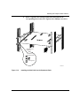
Installing a Shelf in an Equipment Rack
To install a shelf in an equipment rack:
1.
Assemble the shelf unit:
a.
Position the shelf and one bracket as shown in Figure 1-10.
VLK0046A
Figure 1-10.
308224-B Rev 00
Positioning the Shelf and the Bracket
1-15
Installing and Operating the Passport 2430 Multiservice Access Switch
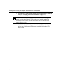
b.
Slide the bracket tabs into the slots on the underside of the shelf as
shown in Figure 1-11.
c.
Insert a screw though the shelf and the corresponding bracket hole as
shown in Figure 1-11. Tighten with a Phillips screwdriver.
VLK0047A
Figure 1-11.
Assembling the Shelf Unit
d.
2.
Repeat steps a through c with the other bracket.
Attach the assembled shelf unit to the equipment rack:
a.
Align the four bracket holes in the shelf unit with four holes in the
equipment rack as shown in Figure 1-12.
Note: If the holes in the rack’s vertical supports are not threaded for cagenut
screws, insert a cage nut in the four locations.
1-16
308224-B Rev 00
Installing the Passport 2430 Chassis
b.
Insert a cagenut screw through each bracket hole and into the
corresponding holes in the rack. Tighten with a Phillips screwdriver.
Cagenut screw
(4 places)
Rail without
threaded holes
Use cage nut
VLK0048A
Figure 1-12.
308224-B Rev 00
Installing the Shelf Unit into the Equipment Rack
1-17
Installing and Operating the Passport 2430 Multiservice Access Switch
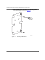
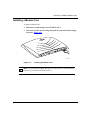
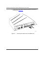
Installing the Passport 2430 on the Shelf
Once you install the shelf unit into the electronic equipment rack, install the
Passport 2430 onto the shelf:
1.
Position the router so that the mounting slots are aligned with the
anchors on the shelf unit (see Figure 1-13).
Anchor
VLK0049A
Figure 1-13.
1-18
Positioning the Passport 2430
308224-B Rev 00
Installing the Passport 2430 Chassis
2.
Slide the Passport 2430 into the shelf, adjusting the router position until
the anchors insert into the Passport 2430 mounting slots (Figure 1-14).
VLK0050A
Figure 1-14.
Installing the Passport 2430 onto a Shelf
The Passport 2430 is now installed securely in the equipment rack.
308224-B Rev 00
1-19
Installing and Operating the Passport 2430 Multiservice Access Switch
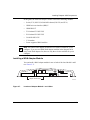
Connecting to the LAN
To connect the Passport 2430 to the LAN, attach the Ethernet LAN cable to the
Ethernet port located on the back of the Passport 2430 (Figure 1-15).
Passport 2430
1
2
10/100
Modem
Console
l
2
Run
Boot
1
Link
TX/RX
Fail
Flash
PCMCIA
O
To LAN
VLK0007A
Figure 1-15.
Connecting to the LAN
Warning: Connecting any other cable to the Ethernet port may seriously
damage the Passport 2430.
Connecting a Management Console
To boot, configure, and manage the Passport 2430, you must connect either a PC
or a terminal to the Passport 2430 to serve as the management console.
Connecting a PC Console
You can use either a desktop or laptop PC as a management console. The
following instructions assume you are using a laptop PC.
Before you connect the Passport 2430 to your laptop PC make sure you have a
terminal emulation program installed on your laptop PC.
1-20
308224-B Rev 00
Installing the Passport 2430 Chassis
To connect a laptop PC to the Passport 2430, make sure that you have the RJ-45 to
DB-9 cable that was shipped with the Passport 2430, then complete the following
steps:
1.
Start your terminal emulation program.
This sets up a dummy terminal that allows you to interface with the router’s
Quick-Start program.
2.
Configure the laptop PC console communication data port using the
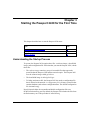
parameters in Table 1-1.
Table 1-1.
PC Console Parameters
Parameter
Value
Baud rate
9600
Data bits
8
Stop bits
1
Parity
None
You can do this either through the terminal emulation program or the PC
control panel and the instructions in your PC documentation.
3.
Insert the blue RJ-45 receptacle end of the console cable into the blue
Passport 2430 Console port (Figure 1-16).
Passport 2430
1
2
10/100
Modem
Console
l
2
Run
Boot
1
Link
TX/RX
Fail
Flash
PCMCIA
O
To laptop
VLK0030A
Figure 1-16.
308224-B Rev 00
Passport 2430 Console Port
1-21
Installing and Operating the Passport 2430 Multiservice Access Switch
4.
Connect the DB-9 end of the cable to the communication data port on the
laptop PC (Figure 1-17).
Passport 2430
1
2
Modem
l
Run
2
Boot
1
Fail
Flash
PCMCIA
O
VLK0009A
Figure 1-17.
Connecting a Laptop PC to a Passport 2430
Connecting a Terminal Console
To connect a terminal console to the Passport 2430, make sure that you have the
RJ-45 to DB-9 cable that was shipped with the Passport 2430 and a DB-9 to
DB-25 adapter, then complete the following steps:
1.
Turn on and configure the terminal, using the parameters in Table 1-2
and the terminal user guide.
Table 1-2.
1-22
Terminal Console Parameters
Parameter
Value
Baud rate
9600
Data bits
8
Stop bits
1
Parity
None
2.
Insert the blue RJ-45 receptacle end of the console cable into the blue
Passport 2430 console connector.
3.
Attach the DB-9 receptacle connector to the DB-9 end of the adapter.
308224-B Rev 00
Installing the Passport 2430 Chassis
4.
Attach the DB-25 end of the adapter to the console host connector
(Figure 1-18).
COMM
20 mA
PR
KB
Passport 2430
1
2
Run
Modem
l
2
Boot
1
Fail
Flash
PCMCIA
O
VLK0005A
Figure 1-18.
308224-B Rev 00
Connecting a Terminal Console to a Passport 2430
1-23
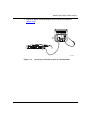
Installing and Operating the Passport 2430 Multiservice Access Switch
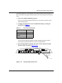
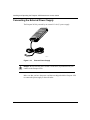
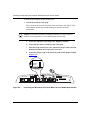
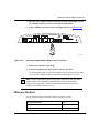
Connecting the External Power Supply
The Passport 2430 is powered by an external 12-volt (V) power supply.
VLK0010A
Figure 1-19.
External Power Supply
Danger: Be sure that the power switch is in the OFF (0) position before you
connect to the Passport 2430.
Make sure that you have the power cord that was shipped with the Passport 2430
to connect the power supply to the wall outlet.
1-24
308224-B Rev 00
Installing the Passport 2430 Chassis
Connect the power supply to the Passport 2430 by following these steps:
1.
Insert the end of the power supply cable to the power port on the
Passport 2430 back panel (Figure 1-20).
2.
Connect the receptacle end of the power cord to the receptacle on the
power supply (Figure 1-20).
Passport 2430
1
2
Run
Modem
l
2
Boot
1
Fail
Flash
PCMCIA
O
VLK0011A
Figure 1-20.
3.
Connecting the Power Supply to the Passport 2430
Connect the power cord to a grounded outlet.
The LEDs on the power supply light.
If the power supply LED is not lit when you plug the power supply into an outlet,
there may be a problem with the power supply. If the power supply LED turns off
when you turn on the Passport 2430, the router may have caused the power supply
to turn off. If either of these problems occur see “How to Get Help” on page xxi.
Where to Go Next
Use the following table to determine where you want to go next.
308224-B Rev 00
For information about
Go to
Installing Passport 2430 Components
Chapter 2
Starting the Passport 2430 for the First Time
Chapter 3
1-25
Chapter 2
Installing Passport 2430 Components
This chapter describes how to install the Passport 2430 components.
Topic
Page
PCMCIA Flash Memory Card
2-1
PCMCIA Modem Card
2-3
WAN Adapter Module
2-6
Where to Go Next
2-11
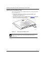
PCMCIA Flash Memory Card
The PCMCIA flash memory card (Figure 2-1) has 16 megabytes (MB) of
memory. It contains the router software and the Passport 2430 boot and diagnostic
code.
SE
IN
RT
FBR0102A
Figure 2-1.
308224-B Rev 00
PCMCIA Flash Memory Card
2-1
Installing and Operating the Passport 2430 Multiservice Access Switch
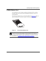
Installing the Flash Memory Card
Before starting the Passport 2430, install the flash memory card supplied with the
router, in PCMCIA slot 1:
1.
Position the card with the label facing up and the INSERT arrow
pointing toward PCMCIA slot 1.
2.
Insert the flash memory card into PCMCIA slot 1 (Figure 2-2) and gently
push the card until it fits snugly into place.
0
43
rt 2
Run
spo
Boot
2
Fail
Pas
CIA
PM
1
VLK0004A
Figure 2-2.
Inserting the Flash Memory Card
Note: The flash memory card can be installed only in PCMCIA slot 1. The
Passport 2430 is unable to boot if you insert the flash memory card in
PCMCIA slot 2.
2-2
308224-B Rev 00
Installing Passport 2430 Components
PCMCIA Modem Card
It is a good idea for you to connect a modem to the Passport 2430. A modem
provides remote access to the router for administrative purposes or in case of
system problems.
Nortel Networks supports the use of the Xircom RM 56 G (Figure 2-3). This is a
Type III, RealPort™ PC card and is capable of modem speeds up to 56 Kb/s.
VLK0003A
Figure 2-3.
Xircom RealPort Modem Card
Note: You can also install an integrated V.34 modem in the WAN adapter slot
for WAN connection and bandwidth on demand (BOD) services. However,
you cannot use this modem for remote administration. To install an integrated
V.34 modem, see “Installing a WAN Adapter Module” on page 2-7.
308224-B Rev 00
2-3
Installing and Operating the Passport 2430 Multiservice Access Switch
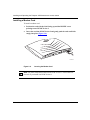
Installing a Modem Card
To install a modem card:
1.
Position the card with the label facing up and the INSERT arrow
pointing toward PCMCIA slot 2.
2.
Insert the card into PCMCIA slot 2 and gently push the card until it fits
snugly into place (Figure 2-4).
0
43
rt 2
Run
spo
Boot
2
Fail
Pas
CIA
PM
1
VLK0013A
Figure 2-4.
Inserting the Modem Card
Note: You must install the modem card in PCMCIA slot 2. The modem will
not work if you install it in PCMCIA slot 1.
2-4
308224-B Rev 00
Installing Passport 2430 Components
3.
Connect the RJ-11 jack from the telephone line directly to the PCMCIA
modem interface (Figure 2-5).
l
2
1
rt 2
spo
Pas
430
2
Run
t
Boo
O
IA
MC
P
Fail
VLK0015A
Figure 2-5.
308224-B Rev 00
Connecting the Telephone Line to the Modem Card
2-5
Installing and Operating the Passport 2430 Multiservice Access Switch
Table 2-1 provides the default settings for the PCMCIA modem cards.
Table 2-1.
Modem Defaults
Modem Signal/Parameter
Default Value
AutoAnswer
Answer on two rings with DTR active
Local character echo
Off
Supervisory functions
Off
Baud rate
9600
Data bits
8
Stop bits
1
Parity
None
WAN Adapter Module
The WAN adapter modules (Figure 2-6) support protocols including
Synchronous, Point-to-Point Protocol (PPP), frame relay, ISDN, and Switched
Multimegabit Data Services (SMDS).
Base module connector
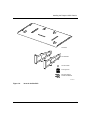
ARN0038A
Figure 2-6.
2-6
WAN Adapter Module
308224-B Rev 00
Installing Passport 2430 Components
In this guide, the term WAN adapter module refers to the following modules:
•
Serial (V.35, RS-232, RS-449/442 balanced, RS-530, and X.21)
•
ISDN basic rate interface (BRI) U
•
ISDN BRI S/T
•
T1/fractional T1 DSU/CSU
•
E1/fractional E1 DSU/CSU
•
56/64 Kb DSU/CSU
•
V.34 modem
•
Future supported WAN modules
Note: One ISDN WAN adapter module has two circuits available for you to
configure. If you use two ISDN WAN adapter modules in the Passport 2430,
one in each WAN adapter slot, there are only three circuits available for you to
configure.
Installing a WAN Adapter Module
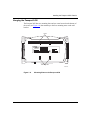
You can install a WAN adapter module in one or both of the slots labeled 1 and 2
(see Figure 2-7).
Passport 2430
1
2
10/100
Console
Run
Modem
l
2
Boot
Link
TX/RX
1
Fail
Flash
PCMCIA
O
Adapter module slots
VLK0016A
Figure 2-7.
308224-B Rev 00
Location of Adapter Module 1 and 2 Slots
2-7
Installing and Operating the Passport 2430 Multiservice Access Switch
To install a WAN adapter module the first time:
1.
Attach the antistatic wrist strap.
The wrist strap directs static electricity from your body to the chassis of the
WAN adapter module, preventing discharge to sensitive electronic
components.
Caution: Electrostatic discharge can damage hardware. You must wear the
antistatic wrist strap whenever you handle printed circuit boards.
a.
Locate the antistatic wrist strap in the shipping container.
b.
Verify that the cable is attached to the wrist strap.
c.
Place the strap around your wrist. Adjust the strap to ensure that the
metal buckle inside the strap touches your skin.
d.
Attach the alligator clip to the metal tab on the WAN adapter module
(Figure 2-8).
U
ISDN BRI
withNT1
Passport 2430
1
2
10/100
Console
Run
Modem
l
2
Boot
Link
TX/RX
1
Fail
Flash
PCMCIA
O
VLK0036A
Figure 2-8.
2-8
Connecting the Wrist Strap Jack to the Metal Tab on a WAN Adapter Module
308224-B Rev 00
Installing Passport 2430 Components
2.
Remove the filler panel from the WAN adapter module slot of your choice
(1 or 2).
a.
Using a Phillips screwdriver, remove the screw that secures the filler
panel to the 1 or 2 WAN adapter module slot (Figure 2-9).
Passport 2430
1
2
10/100
Console
Run
Modem
l
2
Boot
Link
TX/RX
1
Fail
Flash
PCMCIA
O
VLK0017A
Figure 2-9.
Removing the Filler Panel from the 2 WAN Adapter Module Slot
b.
Grasp the metal tab on the filler panel and pull forward to remove the
panel.
c.
Set the filler panel aside.
Note: To operate the Passport 2430 without a WAN adapter module in this
slot, you must reinstall the filler panel.
308224-B Rev 00
2-9
Installing and Operating the Passport 2430 Multiservice Access Switch
3.
Hold the WAN adapter module with the components facing up
(Figure 2-10).
Base module connector
ARN0038A
Figure 2-10.
4.
WAN Adapter Module Ready for Installation
Slide the WAN adapter module into the slot, making sure that the slot
guides engage both sides of the WAN adapter module (Figure 2-11).
0
43
rt 2
Run
spo
Boot
2
Fail
Pas
IA
MC
PC
1
VLK0019A
Figure 2-11.
2-10
Inserting the WAN Adapter Module
308224-B Rev 00
Installing Passport 2430 Components
5.
Push the WAN adapter module in until the connector pins align with the
base module connector socket in the Passport 2430 chassis.
6.
Using a Phillips screwdriver, insert and tighten the screw (Figure 2-12).
Passport 2430
1
2
10/100
Console
Run
Modem
l
2
Boot
Link
TX/RX
1
Fail
Flash
PCMCIA
O
VLK0020A
Figure 2-12.
Securing the WAN Adapter Module to the Front Panel
7.
Remove the antistatic wrist strap.
8.
Connect the appropriate WAN cables to the new interface.
For cabling information, see the WAN module-specific Supplement (that came
with your WAN adapter module) and the Nortel Networks Cable Guide.
Note: See the WAN module-specific Supplement (that came with your WAN
adapter module) for information about the LEDs on the newly installed
module. The new module’s LEDs will not indicate data transfer until you
configure and enable software services.
Where to Go Next
Use the following table to determine where you want to go next.
308224-B Rev 00
For information about
Go to
Starting the Passport 2430 for the First Time
Chapter 3
Operating the Passport 2430
Chapter 4
2-11
Chapter 3
Starting the Passport 2430 for the First Time
This chapter describes how to start the Passport 2430 router.
Topic
Go to
Understanding the Startup Process
3-1
Starting the Passport 2430
3-2
Where to Go Next
3-6
Understanding the Startup Process
To operate, the Passport 2430 requires three files: a software image, a boot ROM
image, and a configuration file. Each time that you start the Passport 2430, it loads
these files.
•
The software image contains a group of executable files that support the
protocols that the Passport 2430 and the network require. The Passport 2430
uses the software image called pp2430.exe.
•
The boot ROM image is called pp2430.ppc.
•
To bridge and route traffic, the Passport 2430 also needs a configuration file
that is tailored to the network. A configuration file is a binary system file that
contains hardware and software configuration data. The default configuration
file is named config.
Nortel Networks ships the executable and default configuration files on a
PCMCIA flash memory card. By default, the Passport 2430 obtains the files from
the flash memory card. This procedure is called booting.
308224-B Rev 00
3-1
Installing and Operating the Passport 2430 Multiservice Access Switch
When you start the Passport 2430 for the first time, it performs diagnostic tests
using the files:
•
pp2430ram.exe, which executes RAM-based diagnostics and loads
RAM-based module diagnostic images.
•
pp2430ienet.a, which tests the 10/100 Ethernet LAN interface.
•
pp2430sdb.a, which tests the COM1 and COM2 interfaces.
After the diagnostic tests are complete, it attempts to boot using the default
configuration file, config, and the software image, pp2430.exe, stored on the flash
memory card. You then create your initial connection to the network by running
the Quick-Start script. The Quick-Start script requires a local console connection
and the flash memory card shipped with the router.
The Passport 2430 boot process repeats until one of the following events occurs:
•
The Passport 2430 boots successfully.
•
You turn off the Passport 2430.
The following sections describe how to start the Passport 2430 by first booting it,
then using Quick-Start to configure the initial connection to the management
console.
Starting the Passport 2430
Before you turn on your router make sure that:
•
The flash memory card is installed in the PCMCIA slot 1 (see “PCMCIA
Flash Memory Card” on page 2-1).
•
The management console is connected to the router (see “Connecting a
Management Console” on page 1-20).
•
If you are using a PC as your management console, your terminal emulation
program is running.
Note: Before starting the boot procedure, ask your network administrator to
assist you in completing the Quick-Start worksheets in Appendix B,
“Quick-Start Worksheets.”
3-2
308224-B Rev 00
Starting the Passport 2430 for the First Time
Accessing a Command-Line Interface
To run the Quick-Start script, you use a command-line interface to access the
router software.
To access a command-line interface, you turn on the Passport 2430 and wait for
the router to perform the diagnostic tests, then boot locally.
When the Passport 2430 boots, its LEDs flash in a particular order. To ensure that
the installation was successful, see “Verifying a Successful Installation” on
page 4-4.
After the Passport 2430 boots, the Technician Interface login prompt appears.
Running the Quick-Start Script
After the router boots and you access the command-line interface, you engage the
Technician Interface. You use the Technician Interface to start the Quick-Start
script that creates the router’s initial IP interface.
You can also configure additional interfaces using Quick-Start, but in most cases
your initial IP interface connects you to the management workstation, where you
can use Site Manager, Bay Command Console (BCC™), or another management
tool to fully customize your router’s configuration.
To engage the Technician Interface, type the following command (noting the use
of an uppercase “M”) at the login prompt and press the Return key:
Manager
The prompt ($) appears. You are now using the Technician Interface.
Note: To check the contents of the router local file system on the installed
flash memory card, type dir and press the Return key. The pp2430.exe
software image, config file, and the inst_pp2430.bat file should appear in the
list of files.
308224-B Rev 00
3-3
Installing and Operating the Passport 2430 Multiservice Access Switch
To run Quick-Start:
1.
Enter the following command to run the Quick-Start script:
run inst_pp2430.bat
The Quick-Start script begins running.
2.
Respond to the prompts, using your worksheets.
Table 3-1 describes the commands that you use to interact with the
Quick-Start script.
Table 3-1.
Quick-Start Commands
Task
Action
Details
Accept the default value.
Press Return.
Your console displays default values in
brackets, for example, [E11].
Repeat a step to make a
correction.
Press Control-c. When prompted, “Terminate script y/n?”
Press n.
press the n key. You return to the
beginning of the step so that you can
reenter the information.
Stop the Quick-Start
installation script.
Press Control-c. When prompted, “Terminate script y/n?”
Press y.
press the y key. The procedure is
terminated and you return to the
Technician Interface prompt.
To restart the Quick-Start procedure, you
must reboot the router by entering boot.
The script prompts you for the following information in the order given:
a. Initial Global Worksheet information
b. Specific protocol information
c. WAN protocol selection
d. Specific protocol information
e. The rest of the Global Worksheet information
After you enter all of the Global Worksheet protocol information, the script
displays a configuration summary and prompts you to save the configuration
to a file.
3-4
308224-B Rev 00
Starting the Passport 2430 for the First Time
3.
Name and save the configuration file.
The script begins to test the configuration on the new IP interface
(Figure 3-1).
Testing local IP interface
ping -IP 192.32.00.000 -r5
IP ping: 192.32.00.000 is
IP ping: 192.32.00.000 is
IP ping: 192.32.00.000 is
IP ping: 192.32.00.000 is
IP ping: 192.32.00.000 is
alive
alive
alive
alive
alive
(size
(size
(size
(size
(size
-
16
16
16
16
16
bytes)
bytes)
bytes)
bytes)
bytes)
This test attempts to ping the Site Manager workstation.
NOTE: If routing has not yet converged, an attempt
to ping the Site Manager workstation may fail. If
this happens, you may either enter a new IP address or
quit and wait a short period of time and try again from
the TI command line.
Type q<return> to cancel this test.
Enter IP address of Site Manager workstation:
Figure 3-1.
4.
Starting the IP Interface Test
To continue the IP configuration test, enter the IP address for the Site
Manager workstation.
To cancel the test, enter q.
308224-B Rev 00
3-5
Installing and Operating the Passport 2430 Multiservice Access Switch
5.
Choose whether you want to configure another module or port.
If you enter n, the Technician Interface prompt appears. If you enter y, the
script prompts you for information about the additional module or port.
Return to step 2 of this procedure.
6.
When the Technician Interface prompt reappears, enter logout to exit the
Technician Interface.
After the router creates and tests the configuration, it starts using the configuration
information that you entered.
Where to Go Next
Use the following table to determine where you want to go next.
3-6
For information about
Go to
Operating the Passport 2430
Chapter 4
308224-B Rev 00
Chapter 4
Operating the Passport 2430
This chapter describes how to operate the Passport 2430 router.
Topic
Page
Understanding the LEDs
4-1
Verifying a Successful Installation
4-4
Diagnostic Software
4-5
Turning the Power On and Off
4-8
Replacing a Flash Memory Card
4-9
Protecting Flash Memory Card Files
4-11
Securing the Passport 2430
4-12
Understanding the LEDs
Light emitting diodes (LEDs) on the Passport 2430 and the WAN adapter modules
provide information about operating the Passport 2430. The following sections
describe LEDs located on the Passport 2430.
Note: For information about LEDs on the WAN adapter modules, see the
module-specific Supplement that came with the WAN adapter module.
308224-B Rev 00
4-1
Installing and Operating the Passport 2430 Multiservice Access Switch
Passport 2430 LEDs
The Passport 2430 has LEDs on the front and on the back panel.
LED on the Front of the Passport 2430
On the front of the Passport 2430 there is an LED (see Figure 4-1) that lights
when the router fails.
Front LED
VLK0033A
Figure 4-1.
LED Located on the Front of the Passport 2430
LEDs on the Back of the Passport 2430
The Passport 2430 has diagnostic and LAN interface LEDs on the back panel as
shown in Figure 4-2.
Passport 2430
1
2
10/100
Console
Run
Modem
l
2
Boot
Link
1
TX/RX
1
Fail
Flash
PCMCIA
O
2
VLK0018A
Figure 4-2.
4-2
LEDs Located on the Back Panel of the Passport 2430
308224-B Rev 00
Operating the Passport 2430
Diagnostic LEDs
The Passport 2430 diagnostic LEDs (Figure 4-3) indicate the status of the router
itself.
Run
Boot
Fail
VLK0021A
Figure 4-3.
Diagnostic LEDs
All of these LEDs light briefly when you turn on the Passport 2430.
Table 4-1 describes what it means when each of the diagnostic LEDs lights.
Table 4-1.
308224-B Rev 00
Base Module Diagnostic LEDs
LED
Meaning
Boot
Diagnostic tests were successful and the Passport 2430 is booting.
Run
The Passport 2430 is operational.
Fail
Diagnostic tests failed.
4-3
Installing and Operating the Passport 2430 Multiservice Access Switch
LAN Interface LEDs
The LAN interface LEDs are on the bottom left and right corners of the LAN port,
which is labeled 10/100.
10/100
Link
TX/RX
VLK0032A
Figure 4-4.
LAN Port and Interface LEDs
The Link LED lights when you establish an Ethernet connection.
The TX/RX LED lights when data passes to or from the router.
Verifying a Successful Installation
After connecting the Passport 2430 to the network, you can verify a successful
installation by checking the diagnostic LEDs on the back panel of the Passport
2430 (Figure 4-5).
Run
Boot
Fail
VLK0021A
Figure 4-5.
4-4
Diagnostic LEDs
308224-B Rev 00
Operating the Passport 2430
When you turn on the Passport 2430, the following sequence of back panel LED
activity should occur:
•
All base module LEDs light momentarily.
•
The Run LED lights until the Passport 2430 completes all diagnostic tests.
If the system fails its diagnostic test, the Fail LED lights.
•
After completing the diagnostic testing procedure, the boot process begins. As
the Passport 2430 boots, the Boot LED lights and the Run LED is off.
During the boot process, if the pp2430.ppc file is not found, the Boot LED
turns off and the Fail LED lights.
•
After the boot process completes, the Run LED lights and the Boot LED turns
off, indicating that the Passport 2430 is operational.
If the LEDs on the Passport 2430 light in this sequence, you have successfully
installed the Passport 2430. Contact your network administrator to verify that the
Passport 2430 is now connected to the network.
If you need additional assistance, contact your local Nortel Networks Technical
Solutions Center.
Diagnostic Software
Diagnostic software runs a sequence of tests on the Passport 2430 CPU and
module hardware. This software runs automatically when you start the Passport
2430 (before booting) or when you enter the following command from the
command-line interface:
diags
308224-B Rev 00
4-5
Installing and Operating the Passport 2430 Multiservice Access Switch
The following lists each test the software runs in the appropriate order, and
explains all possible results of each test.
Table 4-2.
Diagnostic Testing
Diagnostic Test
Possible Results
Testing CPU Board
PASSED - diagnostic test proceeds to test the next
module.
FAILED
• non-bootable failure - There is a problem in the
hardware necessary to run the Passport 2430.
The software displays the following message:
The CPU board FAILED HARDWARE
DIAGNOSTICS. This is a non bootable
failure. Not Attempting Boot.
In the event of a non-bootable failure, the
Passport 2430 will not boot.
•
bootable failure - There is a problem in the
hardware that is not immediately necessary to
run the Passport 2430 (for instance if the LAN
port failed). The software displays the following
message:
The CPU board FAILED HARDWARE
DIAGNOSTICS. This is a bootable
failure.
The software proceeds to test the next module.
(continued)
4-6
308224-B Rev 00
Operating the Passport 2430
Table 4-2.
Diagnostic Test
Diagnostic Testing
Possible Results (continued)
Testing SDB Module PASSED - The WAN adapter module is operational.
in Slot 1
The software proceeds to test the next module.
FAILED - The WAN adapter module is not
operational. The software proceeds to test the next
module.
NOT PRESENT - There is no WAN adapter module
in Slot 1. The software proceeds to test the next
module.
Testing SDB Module PASSED - The WAN adapter module is operational.
in Slot 2
The software starts the bootstrap.
FAILED - The WAN adapter module is not
operational. This is considered a bootable error; the
software starts the bootstrap.
NOT PRESENT - The software does not detect a
WAN adapter module in Slot 2. The software starts
the bootstrap.
If you need assistance, contact your local Nortel Networks Technical Solutions
Center.
Enabling and Disabling Diagnostic Software
If you do not want diagnostic testing when the Passport 2430 starts, disable the
diagnostic software by entering:
diags-off
The diagnostic testing will not run when you start the Passport 2430.
Note: Although disabling the diagnostic software decreases the start-up time,
Nortel Networks recommends that the diagnostic software runs by default
when you start the Passport 2430.
308224-B Rev 00
4-7
Installing and Operating the Passport 2430 Multiservice Access Switch
To re-enable the diagnostic software, enter:
diags-on
The diagnostic testing now runs when you start the Passport 2430.
Turning the Power On and Off
The power switch is located on the back of the Passport 2430 (Figure 4-6).
Passport 2430
1
2
10/100
Console
Run
Modem
l
2
Boot
Link
TX/RX
1
Fail
Flash
PCMCIA
O
Power switch
VLK0035A
Figure 4-6.
Power Switch
To turn on the Passport 2430, press the power switch to the ON (1) position.
The logo on the front lights and the back panel LEDs will step through the
sequence described in “Verifying a Successful Installation” on page 4.” If the
LEDs on the power supply do not light, or the front LED (see Figure 4-1 on page
4-2) and the Fail LED (see Figure 4-5 on page 4-4) remain on, turn the power
switch to the OFF position. Wait 1 minute and then turn the power switch to the
ON position.
If the Passport 2430 does not turn on, check the power supply cable connections.
See “Connecting the External Power Supply” on page 1-24 for information. If the
Passport 2430 still does not power on, or the LEDs that indicate failure remain on,
contact the Nortel Networks Technical Solutions Center.
Note: When the front logo lights, there may be variation in the lighting or the
light may dim. This does not indicate a problem.
To turn off the Passport 2430, press the power switch to the OFF (0) position.
4-8
308224-B Rev 00
Operating the Passport 2430
Replacing a Flash Memory Card
To replace a flash memory card in a Passport 2430:
Caution: Do not remove the flash memory card while the router is operating.
Removing the flash memory card interferes with current networking
operations.
1.
Press the eject button next to the card receptacle on the back panel
(Figure 4-7).
The card pops out slightly.
0
43
rt 2
spo
Run
2
Fail
Pas
CIA
PM
Boot
1
1
2
VLK0014A
Figure 4-7.
Ejecting a Passport 2430 Flash Memory Card
2.
Pull the flash memory card out of the card receptacle.
Caution: Do not remove the flash memory card while the router is operating.
Removing the flash memory card interferes with current networking
operations.
308224-B Rev 00
4-9
Installing and Operating the Passport 2430 Multiservice Access Switch
To insert another flash memory card into the slot:
1.
Position the card with the label facing up and the INSERT arrow
pointing toward the card receptacle.
2.
Insert the card into the bottom PCMCIA slot (Figure 4-8) and gently
push in the card until it fits snugly into place.
0
43
rt 2
Run
spo
Boot
2
Fail
Pas
CIA
PM
1
VLK0004A
Figure 4-8.
Inserting the Flash Memory Card
When you remove a formatted flash memory card, the nonvolatile file system
(NVFS) automatically removes access to the card. When you insert and format a
card or insert an already formatted card, the NVFS automatically provides access.
4-10
308224-B Rev 00
Operating the Passport 2430
Protecting Flash Memory Card Files
Nortel Networks ships each flash memory card with its read/write protect switch
in the unprotected position (Figure 4-9). After successfully loading the
configuration file and saving your configuration, you may want to write-protect
the flash memory card for backup purposes.
Note: You typically do not operate the Passport 2430 with a write-protected
flash memory card. You should make a copy of your configuration on another
flash memory card, write-protect that card, and store it in a safe place.
To change flash memory card protection:
1.
Remove the flash memory card as described in “Replacing a Flash
Memory Card” on page 4-9.
2.
Adjust the read-write protect switch, which is located on the edge
opposite the INSERT arrow of the flash memory card (Figure 4-9).
Unprotected
RT
SE
IN
Insert
Protected
VLK0002A
Figure 4-9.
3.
308224-B Rev 00
Flash Memory Card Read/Write Protect Switch
Reinsert the flash memory card into the card receptacle (refer to Figure
4-8 on page 4-10).
4-11
Installing and Operating the Passport 2430 Multiservice Access Switch
Securing the Passport 2430
The security slot (Figure 4-10) allows you to use a Kensington lock, or other
similar laptop type lock.
Security slot
Passport 2430
1
2
10/100
Console
Modem
l
Run
2
Boot
Link
TX/RX
1
Fail
Flash
PCMCIA
O
VLK0056A
Figure 4-10.
4-12
Security Slot
308224-B Rev 00
Chapter 5
Adding and Replacing a WAN Adapter Module
This chapter describes how to add and replace a WAN adapter module in the
Passport 2430.
Before installing the module, examine the contents of your WAN adapter module
upgrade kit. If any parts appear damaged, call the Nortel Networks Technical
Solutions Center immediately.
Topic
Page
Downloading New Boot and Diagnostic Code
5-1
Preparing to Install the WAN Adapter Module
5-2
Installing a WAN Adapter Module
5-6
Note: This chapter provides generic instructions that apply to all Passport
2430 WAN adapter modules. For specific information about the module that
you are installing, refer to the module-specific Supplement, which ships in the
WAN adapter module upgrade kit.
Downloading New Boot and Diagnostic Code
If you are installing a WAN adapter module as an upgrade to your existing
hardware configuration, you must verify that the Passport 2430 contains the
minimum required version of programmable read-only memory (PROM) code for
the module that you are installing. The release media includes the latest boot and
diagnostic code at the time it is shipped, but if your upgrade requires newer code,
you must manually download the boot images to the memory flash card and the
diagnostic images to the diagnostic PROM.
308224-B Rev 00
5-1
Installing and Operating the Passport 2430 Multiservice Access Switch
To determine which version of boot and diagnostic code you need when installing
a particular WAN adapter module, see the module-specific Supplement that ships
with the module. For instructions on how to upgrade the PROM code in flash
memory, refer to Upgrading Routers to BayRS Version 14.xx.
Preparing to Install the WAN Adapter Module
Before installing a WAN adapter module:
1.
Turn off the Passport 2430.
Set the power switch on the power supply to off, 0 (see “Turning the Power
On and Off” on page 4-8).
Warning: You cannot hot-swap Passport 2430 WAN adapter modules.
2.
Attach an antistatic wrist strap.
The wrist strap directs static electricity from your body to the chassis of the
WAN adapter module, preventing discharge to sensitive electronic
components.
Caution: Electrostatic discharge can damage hardware. You must wear the
antistatic wrist strap whenever you handle printed circuit boards.
5-2
a.
Locate the antistatic wrist strap in the shipping container.
b.
Verify that the cable is attached to the wrist strap.
c.
Place the strap around your wrist. Adjust the strap to ensure that the
metal buckle inside the strap touches your skin.
d.
Attach the alligator clip to the metal tab on the WAN adapter module
(Figure 5-1).
308224-B Rev 00
Adding and Replacing a WAN Adapter Module
U
ISDN BRI
withNT1
Passport 2430
1
2
10/100
Console
Run
Modem
l
2
Boot
Link
1
Fail
TX/RX
Flash
O
PCMCIA
VLK0036A
Figure 5-1.
Connecting the Wrist Strap Jack to the Metal Tab on a WAN Adapter Module
3.
Remove the installed WAN adapter module or the slot filler panel from
either 1 or 2 (see Figure 5-2).
•
To install the WAN adapter module in an empty slot, go to “Removing the
Filler Panel” on page 5-4.
•
To replace an installed WAN adapter module, go to “Removing a WAN
Adapter Module.”
Passport 2430
1
2
10/100
Console
Run
Modem
l
2
Boot
Link
TX/RX
1
Fail
Flash
PCMCIA
O
Adapter module slots
VLK0016A
Figure 5-2.
308224-B Rev 00
Location of the WAN Adapter Module 1 and 2 Slots
5-3
Installing and Operating the Passport 2430 Multiservice Access Switch
Removing the Filler Panel
Remove the filler panel from the empty WAN adapter module slot:
1.
Using a Phillips screwdriver, remove the screw that secures the filler
panel in the slot labeled either 1 or 2 (Figure 5-3).
Passport 2430
1
2
10/100
Console
Run
Modem
l
2
Boot
Link
TX/RX
1
Fail
Flash
PCMCIA
O
VLK0017A
Figure 5-3.
Removing the Filler Panel from the 2 Slot
2.
Grasp the metal tab on the filler panel and pull forward to remove the
panel.
3.
Set the filler panel aside.
Note: To operate the Passport 2430 without a WAN adapter module in this
slot, you must reinstall the filler panel.
4.
5-4
Go to “Installing a WAN Adapter Module” on page 5-6.
308224-B Rev 00
Adding and Replacing a WAN Adapter Module
Removing a WAN Adapter Module
To remove a WAN adapter module:
1.
Using a Phillips screwdriver, remove the screw that secures the WAN
adapter module that you want to replace (Figure 5-4).
Passport 2430
1
2
10/100
Console
Run
Modem
l
2
Boot
Link
TX/RX
1
Fail
Flash
PCMCIA
O
VLK0020A
Figure 5-4.
Removing the WAN Adapter Module Screw
2.
Pull the WAN adapter module toward you to detach it from the base
module connector in the Passport 2430 chassis.
Grasp the WAN adapter module’s metal tab, or insert a thin tool (such as a
flat-tip screwdriver) in the slot on the tab.
Be prepared to apply some force, but stop pulling immediately as soon as the
WAN adapter module is free from the base module connector.
308224-B Rev 00
3.
Slide the WAN adapter module all the way out of the slot.
4.
Place the WAN adapter module in an antistatic bag.
5.
Go to the next section, “Installing a WAN Adapter Module.”
5-5
Installing and Operating the Passport 2430 Multiservice Access Switch
Installing a WAN Adapter Module
To install a WAN adapter module:
1.
Hold the WAN adapter module with the components facing up
(Figure 5-5).
Base module connector
ARN0038A
Figure 5-5.
2.
WAN Adapter Module Ready for Installation
Slide the WAN adapter module into the slot, making sure that the slot
guides engage both sides of the WAN adapter module (Figure 5-6).
0
43
rt 2
spo
Run
2
Fail
Pas
IA
MC
PC
Boot
1
VLK0019A
Figure 5-6.
5-6
Inserting the WAN Adapter Module
308224-B Rev 00
Adding and Replacing a WAN Adapter Module
3.
Push the WAN adapter module in until its connector pins align with the
base module connector socket in the Passport 2430 chassis.
4.
Using a Phillips screwdriver, insert and tighten the screw (Figure 5-7).
Passport 2430
1
2
10/100
Console
Run
Modem
l
2
Boot
Link
TX/RX
1
Fail
Flash
PCMCIA
O
VLK0031A
Figure 5-7.
Securing the WAN Adapter Module to the Back Panel
5.
Remove the antistatic wrist strap.
6.
Connect the appropriate WAN cables to the new interface.
For cabling information, see the module-specific Supplement that came with
the WAN adapter module and the Nortel Networks Cable Guide.
Before you can use the WAN adapter module after installation, you must start the
router on the network and modify its configuration file to include the new
interface.
See the module-specific Supplement that came with the WAN adapter module for
a list of software installation tasks and related documentation.
Note: Configuring software for additional interfaces may increase the
Passport 2430 memory requirements.
308224-B Rev 00
5-7
Installing and Operating the Passport 2430 Multiservice Access Switch
7.
Turn the power supply on and check the Passport 2430 LEDs on the back
panel (see “Verifying a Successful Installation” on page 4-4).
Note: See the module-specific Supplement that came with the WAN adapter
module for information about the LEDs on the newly installed module. The
new module’s LEDs will not indicate data transfer until you configure and
enable software services.
If the WAN module fails its diagnostic test, the Fail LED on the back panel
and the front of the Passport 2430 remains on and the WAN module LED
flashes rapidly.
5-8
308224-B Rev 00
Chapter 6
Replacing a PCMCIA Modem Card
This chapter describes how to remove and install a PCMCIA modem card in the
Passport 2430 router.
Topic
Page
Removing a Modem Card
6-2
Installing a Modem Card
6-3
A modem installed in the Passport 2430 provides remote access to the system for
the administrator. Nortel Networks supports the use of the Xircom RM 56 G
(Figure 6-1). This is a Type III, RealPort™ PC card and is capable of modem
speeds up to 56 Kb/s.
VLK0003A
Figure 6-1.
308224-B Rev 00
Xircom RealPort Modem Card
6-1
Installing and Operating the Passport 2430 Multiservice Access Switch
Note: You can also install an Integrated V.34 modem in either WAN adapter
slot (COM1 or COM2) for WAN connection and bandwidth-on-demand
services. However, you cannot use this modem for remote administration. To
install an Integrated V.34 modem, see “Installing a WAN Adapter Module” on
page 2-7 or Chapter 5, “Adding and Replacing a WAN Adapter Module.”
The next sections describe how to remove and install a PCMCIA modem card. If
you are adding a modem card into an empty slot, go directly to “Installing a
Modem Card” on page 6-3.
Removing a Modem Card
To remove a modem card from the Passport 2430:
1.
Detach the telephone line from the modem card jack.
2.
Press the modem button, which is next to PCMCIA slot 2 on the back
panel.
The card pops out slightly.
3.
Pull the modem card out of the card receptacle (Figure 6-2).
0
43
rt 2
Run
spo
Boot
2
Fail
Pas
CIA
PM
1
1
2
VLK0022A
Figure 6-2.
6-2
Removing a Passport 2430 Modem Card
308224-B Rev 00
Replacing a PCMCIA Modem Card
Installing a Modem Card
To install a modem card:
1.
Position the card pointing toward PCMCIA slot 2.
2.
Insert the card into the slot and gently push the card in until it fits snugly
into place (Figure 6-3).
0
43
rt 2
Run
spo
Boot
2
Fail
Pas
CIA
PM
1
VLK0013A
Figure 6-3.
Inserting the Modem Card
Note: You can install a modem card only in PCMCIA slot 2. The modem will
not work if you install it in PCMCIA slot 1.
308224-B Rev 00
6-3
Installing and Operating the Passport 2430 Multiservice Access Switch
3.
Connect the J-11 jack from the telephone line directly to the PCMCIA
modem interface (Figure 6-4).
l
2
1
t
por
s
Pas
2
0
243
Run
t
Boo
O
CIA
PM
Fail
VLK0015A
Figure 6-4.
6-4
Connecting the Telephone Line to the Modem Card
308224-B Rev 00
Replacing a PCMCIA Modem Card
Table 6-1 provides the default settings for the modem card.
Table 6-1.
Modem Defaults
Modem Signal/Parameter
Default Value
Auto answer
Answer on two rings with DTR active
Local character echo
Off
Supervisory functions
Off
Baud rate
9600
Data bits
8
Stop bits
1
Parity
None
Modem Card Support
For assistance in diagnosing and resolving any modem problem, contact the
Nortel Networks Technical Solutions Center (see “How to Get Help” on
page xxi). If the Technical Solutions Center determines that the problem is related
to the modem card, rather than the Passport 2430 software, you will need to
contact Xircom technical support at the following URL:
http://www.xircom.com.
308224-B Rev 00
6-5
Chapter 7
Upgrading Memory
If you want to upgrade your router by adding more memory, you can install a 16
or 32 MB single inline memory module (SIMM). This chapter describes how to
replace or install a SIMM in the Passport 2430.
Topic
Page
Installing the SIMM
7-1
Installing the SIMM
You install a SIMM in the Passport 2430 with the following steps:
1.
Turn off the Passport 2430.
2.
Take the cover off the chassis.
3.
Insert the SIMM into the SIMM slot.
4.
Replace the cover of the chassis.
5.
Turn on the Passport 2430.
The following sections explain each step in greater detail.
308224-B Rev 00
7-1
Installing and Operating the Passport 2430 Multiservice Access Switch
Turn Off the Passport 2430
Turn off the Passport 2430:
1.
Press the power switch to the off (0) position (Figure 7-1).
Passport 2430
1
2
10/100
Console
Run
Modem
l
2
Boot
Link
TX/RX
1
Fail
Flash
PCMCIA
O
Power switch
VLK0035A
Figure 7-1.
Power Switch
2.
7-2
Pull the power supply plug out of the wall outlet.
308224-B Rev 00
Upgrading Memory
Remove the Cover from the Chassis
Take the cover off the Passport 2430 chassis:
1.
Turn the Passport 2430 upside down and remove the four screws as
shown in Figure 7-2.
ATTACH WALL MOUNT BRACKET HERE
Passport 2430
M/N
S/N
P/N
VLK0052A
Figure 7-2.
308224-B Rev 00
Removing the Screws from the Passport 2430
7-3
Installing and Operating the Passport 2430 Multiservice Access Switch
2.
Carefully turn the Passport 2430 rightside up, grasp the cover near the
front and pull up and remove as shown in Figure 7-3.
VLK0053A
Figure 7-3.
3.
Removing the Chassis Cover
Locate the SIMM slot (see Figure 7-4).
SIMM
VLK0051A
Figure 7-4.
Location of the SIMM Slot
If there is already a SIMM in the SIMM slot, go to ““Removing a SIMM” on page
7-5. Otherwise go to ““Inserting a SIMM” on page 7-6.
7-4
308224-B Rev 00
Upgrading Memory
Removing a SIMM
To remove a SIMM currently in the Passport 2430:
1.
Pull the tabs on either side of the SIMM as shown in Figure 7-5.
The SIMM will pop up.
VLK0058A
Figure 7-5.
2.
308224-B Rev 00
Pull the Tabs on Either Side of the SIMM
Grasp the SIMM and pull as shown in Figure 7-5.
7-5
Installing and Operating the Passport 2430 Multiservice Access Switch
Inserting a SIMM
To insert the SIMM:
1.
Position the SIMM so that the notch on the SIMM lines up with the
socket key on the SIMM slot.
2.
Gently push the SIMM into the slot (see Figure 7-6).
When in place, the SIMM pops-up.
Notch
Socket key
2
1
VLK0054A
Figure 7-6.
3.
7-6
Position and Insert the SIMM (1), then Push the
SIMM Down (2)
Push the SIMM down until you hear or feel a click (see Figure 7-6).
308224-B Rev 00
Upgrading Memory
Replacing the Chassis Cover
After you install the SIMM, replace the chassis cover:
1.
Lining up the back of the cover and the slots on the back of the chassis, fit
the cover back on the chassis as shown in Figure 7-7.
Passport 2430
1
2
10/100
Console
Run
Modem
l
2
Boot
Link
TX/RX
1
Fail
Flash
PCMCIA
O
VLK0059A
Figure 7-7.
2.
Replacing the Chassis Cover
Turn the Passport 2430 upside down and replace the four screws.
Starting the Passport 2430
After you install the SIMM and replace the chassis cover, start the Passport 2430:
1.
Plug the power supply cord into the wall outlet.
2.
Press the power switch to the on (1) position.
The Passport 2430 automatically finds and configures for the SIMM when it
boots.
308224-B Rev 00
7-7
Appendix A
Passport 2430 Technical Specifications
This appendix provides technical specifications and a product overview of the
Passport 2430 and its interface options.
Topic
Page
Physical Specifications
A-1
Electrical Specifications
A-3
Environmental Specifications
A-3
Hardware Communications Options
A-4
Physical Specifications
The dimensions and weight of the Passport 2430 are:
•
•
•
•
Height: 2.1 in. (5.4 cm)
Width: 14.4 in. (36.7 cm)
Depth: 8.0 in. (20.3 cm)
Weight: 3.5 lb (1.4 kg)
The Passport 2430 has an external power supply. The physical specifications for
the power supply are:
308224-B Rev 00
•
•
•
Height: 1.4 in. (3.6 cm)
Width: 2.6 in. (5.1 cm)
Length: 6.0 in. (15.2 cm)
•
Weight: 1 lb (0.4 kg) maximum
•
Cable: 6.5 in. (16.5 cm)
A-1
Installing and Operating the Passport 2430 Multiservice Access Switch
Your installation site must provide two inches of free space above the Passport
2430 to dissipate heat. Minimum space requirements for installing the Passport
2430 at your site are:
•
•
•
Height: 3.4 in. (8.6 cm)
Width: 14.4 in. (36.7 cm)
Depth: 8.0 in. (20.3 cm)
Note: The minimum space requirements assume the external power supply is
on a separate area, but within 6.5 inches (16.51 cm) of the Passport 2430
power connector.
The power supply must be installed as follows:
•
Proximity to Passport 2430: within 6.5 in. (16.5 cm)
•
Proximity to the wall receptacle: 6 ft (2 m)
If you are installing the Passport 2430 in an equipment rack, make sure that the
rack meets the following specifications:
•
•
•
•
A-2
Heavy-duty steel construction
Electronic Industries Association (EIA) standard hole-spacing
Width of 19 in. (48 cm)
Depth of 24 in. (61 cm)
308224-B Rev 00
Passport 2430 Technical Specifications
Electrical Specifications
Your installation site must meet the following power requirements:
•
•
•
Proximity to power outlet: within 6 ft (2 m) of the power supply
Voltage: 120 to 240 VAC
Amperage: 0.6 A
Table A-1 lists the wall outlet requirements.
Table A-1.
Passport 2430 Power Outlet Requirements
Country
Outlet
Voltage
United States/
Canada
National Electrical Manufacturers
Association (NEMA) 5-15P standard outlet
100-120 V
Any other country Your Passport 2430 distributor informs you
of the outlet you need
200-240 V
Environmental Specifications
The environmental requirements for the Passport 2430 are as follows:
•
•
•
Altitude: 0 to 8000 ft (0 to 2438.4 m)
Humidity: 10% to 90%, noncondensing
Temperature: 32° to 104°F (0° to 40°C)
The environmental requirements for the Passport 2430 power supply are as
follows:
308224-B Rev 00
•
Altitude: 0 to 10,000 ft (0 to 3,048 m)
•
Humidity: 5% to 85% at 104°F (40°C)
•
Temperature: 32° to 104°F (0° to 40°C)
A-3
Installing and Operating the Passport 2430 Multiservice Access Switch
Hardware Communications Options
Passport 2430 connects to an Ethernet LAN and supports the following WAN
adapter modules:
•
One serial interface
•
One ISDN BRI S/T interface
•
One ISDN BRI U interface
•
One V.34 modem interface
•
One 56/64K DSU/CSU interface
•
One E1/fractional E1 DSU/CSU interface
•
One T1/fractional T1 DSU/CSU interface
Table A-2 describes each interface.
Table A-2.
Network Interfaces Available on the Passport 2430
Network
Interface
Description
Ethernet
Supports the Ethernet and IEEE 802.3 standards that provide LAN connectivity.
The Ethernet interface on the base module is a 10/100BASE-TX.
10/100BASE-TX interfaces provide broadband, baseband, and fiber support,
depending on the transceiver and cables that you use.
Serial
Provides WAN connectivity. Passport 2430 models have one or two serial ports, one on
each WAN adapter module.
Each port operates independently with RS-232, RS-422, RS-449, RS-530, V.28, V.35,
and X.21 cables. Serial capability allows internal or external clocking.
ISDN BRI
Supports an S/T or U interface. The BRI provides two B channels and supports full
D-channel signaling and call setup/teardown as defined in 1988 CCITT (now ITU-T)
Q.921 and Q.931. For more information on ISDN, functional groups, or reference
points, see Configuring Dial Services.
The ISDN BRI option is available as a WAN adapter module for any Passport 2430
model.
(continued)
A-4
308224-B Rev 00
Passport 2430 Technical Specifications
Table A-2.
Network Interfaces Available on the Passport 2430 (continued)
Network
Interface
Description
56/64K DSU/CSU
Supports a 56/64K DSU/CSU interface.
FT1/T1 and
Provides an interface to convert incoming packet data from an external T1 or E1 line
FE1/E1 DSU/CSU (using an RJ-48C connector). Because the interface integrates the channel service unit
(CSU) function on each T1 or E1 port, it allows direct connection to the network. A T1
port can transmit or receive a total of 24 DS0 HDLC channels for each DS1 frame.
V.34 modem
Provides a V.34 modem interface.
Ethernet 10/100BASE-TX Interface
Note: For the proper cable pin assignments to use for each interface type, see
the Nortel Networks Cable Guide.
The Passport 2430 base module has a Level One LXT907A Ethernet transceiver,
which is a dual-speed (10/100) Fast Ethernet port. Table A-3 identifies the pin
assignments for this interface.
Table A-3.
Pin Assignment
12345678
308224-B Rev 00
10/100BASE-TX Interface Pin Assignments
Pin No.
Signal (Function)
1
TD+ (Transmit to UTP wire)
2
TD- (Transmit to UTP wire)
3
RD+ (Receive from UTP wire)
4
Not used
5
Not used
6
RD- (Receive from UTP wire)
7
Not used
8
Not used
A-5
Installing and Operating the Passport 2430 Multiservice Access Switch
Serial Interfaces
The Passport 2430 base module has internal and external UART connectors. The
external UART connector (the console port) uses a 9-pin D-sub connector
(Table A-4).
Table A-4.
Local Console Port RJ-45 Pin Assignments
Pin Assignment
12345678
A-6
Pin No.
Signal Name
1
CTS
2
DSR
3
RXD
4
DCD
5
TXD
6
Ground
7
DTR
8
RTS
308224-B Rev 00
Appendix B
Quick-Start Worksheets
This appendix provides information and worksheets that aid you in responding to
the Quick-Start prompts that occur when you configure the Passport 2430 after
booting for the first time.
Topic
Page
Understanding Quick-Start Connector Names and Numbers
B-2
Filling Out the Worksheets
B-2
Global Information Worksheet
B-3
Router Protocol Worksheets
B-5
WAN Protocol Worksheets
B-11
You can also configure additional interfaces using Quick-Start, but in most cases
your initial IP interface connects you to the management workstation, where you
can use Site Manager, BCC, or another management tool to fully customize your
router’s configuration.
Fill out the worksheets with assistance from your network administrator. The
worksheets contain options that appear at each prompt when configuring a serial
interface, and space for you to enter your own information. If you are configuring
an interface other than the serial interface, the prompts will differ from those
shown in the sample worksheets. In that case, use the sample worksheets only as a
guide and review the actual Quick-Start prompts and options carefully before
replying.
Be sure to fill out the worksheets and read all sections of this appendix before you
run the Quick-Start script.
308224-B Rev 00
B-1
Installing and Operating the Passport 2430 Multiservice Access Switch
Understanding Quick-Start Connector Names and Numbers
The Quick-Start script assigns a name and number to the LAN and two WAN
interfaces, depending on their location on the Passport 2430.
Table B-1 provides the appropriate connector names and numbers that you use to
configure an interface during the Quick-Start procedure.
Table B-1.
Quick-Start Connector Names and Numbers
Module
Interface*
Base
Adapter 1
Adapter 2
Ethernet
XCVR1
N/A
N/A
Serial
N/A
COM1
COM2
56/64K, T1/FT1, or
E1/FE1 DSU/CSU
N/A
COM1
COM2
* The Quick-Start script does not support initial ISDN or V.34 interface
configuration.
Filling Out the Worksheets
The inst_pp2430.bat script provides many options for configuring the Passport
2430 on a network. Because typical remote access uses a serial interface over a
wide area connection, this sample describes only the options involved with a serial
configuration.
Note: This section provides worksheets only for a serial interface
configuration over a wide area connection. It does not contain worksheets for
LAN configuration options. If you are configuring a LAN interface, read the
Quick-Start text and prompts carefully before responding.
We suggest the following procedure when you fill out the worksheets:
1.
Fill out the Global Information Worksheet completely.
The sample worksheet lists options common to all serial interface
configurations.
2.
B-2
After you record your protocol selections on the Global Information
Worksheet, fill out one Routing Protocol worksheet.
308224-B Rev 00
Quick-Start Worksheets
This worksheet lists specific options for RIP, OSPF, and static route
configurations. For example, if you select RIP as your routing protocol, you
need to fill out only the worksheet pertaining to RIP.
3.
Fill out one WAN Protocol worksheet.
This worksheet lists specific options for Nortel Networks (proprietary)
Point-to-Point Protocol (PPP), frame relay, Standard PPP, and Switched
Multimegabit Data Service (SMDS) configurations. For example, if you select
frame relay as your wide area protocol, you need to fill out only the frame
relay worksheet.
Global Information Worksheet
This worksheet profiles the prompts and possible options relating to all Passport
2430 serial configurations. Write your selection in the “Your Response” column.
Global Information Worksheet
Step
Requested Information
Options
Your Response
1
Enter the module number [1]:
The script lists the available
modules that you can use to
connect the router’s IP network
interface to Site Manager.
Enter the number that
corresponds to the
module that you want to
use.
For example, the script might
offer the following options:
1. 10/100 BASE-TX Ethernet on
Base Module
2. Serial on Adapter Module 1
2
Driver Type:
If there is only one interface on
the module you chose, the script
automatically selects the driver
type for that interface and
bypasses this prompt. Otherwise,
the script displays a menu of
driver types. The actual list
depends on the modules that you
have installed.
Choose the synchronous
driver.
(continued)
308224-B Rev 00
B-3
Installing and Operating the Passport 2430 Multiservice Access Switch
Global Information Worksheet (continued)
Step
Requested Information
Options
Enter the line speed:
more info needed
Enter circuit name [S#]:
The script displays a default
circuit name for the COM
interface you selected (for
example, E11 for COM1 and E12
for COM2).
Enter IP address in dotted
decimal notation:
Enter the IP address for the COM
interface.
Enter IP subnetwork mask in
dotted decimal notation:
Enter the subnet mask for the
COM interface IP address.
Is the router connected to
the same local area network
as the Site Manager
workstation? (y/n) [n]:
y(es)
n(o)
Press the Return key.
Enter routing protocol
number [1]:
1. RIP
2. OSPF
3. Static Route to Site Manager
(Complete the worksheet
for the protocol that you
select.)
Enter wide area protocol
number [1]:
1. Bay Networks Point-to-Point
Protocol (Proprietary)
2. Frame relay
3. Point-to-Point Protocol (PPP)
Standard
4. Switched Multimegabit Data
Service (SMDS)
(Complete the worksheet
for the protocol that you
select.)
Do you wish to set
SNMP community
management?
(y/n) [n]:
y(es)
n(o)
4
Enter (TFTP) volume number
[1]:
The script automatically selects
“1” as the TFTP default volume.
5
Do you want to enable
FTP? (y/n) [n]:
y(es)
n(o)
3
Your Response
Press the Return key.
Setting up SNMP community
management is optional.
Enabling FTP is optional.
(continued)
B-4
308224-B Rev 00
Quick-Start Worksheets
Global Information Worksheet (continued)
Step
6
Requested Information
Options
Enter (FTP) volume number
[1]:
The script automatically selects
“1” as the FTP default volume.
Do you want to enable TI
TELNET? (y/n) [n]:
y(es)
n(o)
Your Response
Enabling telnet is optional.
7
Do you wish to enable HTTP
(Web) Server? (y/n) [n]
y(es)
n(o)
Enabling HTTP Web server is
optional.
8
Do you wish to save this
configuration to a file? (y/n) [y]
y(es)
n(o)
Press the Return key.
Enter filename [startup.cfg]:
We recommend using the default
filename.
Press the Return key.
Do you wish to set up another
port/module? (y/n) [y]
y(es)
n(o)
Type n and press the
Return key.
Router Protocol Worksheets
If Site Manager is not on the same network as Passport 2430, you must configure
an IP routing protocol so you can remotely manage the router. The worksheets in
this section point you to information that you need to appropriately configure each
of the following types of protocols:
308224-B Rev 00
•
RIP
•
OSPF
•
Static route
B-5
Installing and Operating the Passport 2430 Multiservice Access Switch
RIP Worksheet
The Router Information Protocol (RIP) is a protocol that uses the number of hops
to measure network distance. Complete the following worksheet if you will use
RIP to access Site Manager.
RIP Worksheet
Requested Information
Options
RIP will listen to a specific route to the
network or subnet where Site Manager
is located. If you would also like RIP to
listen to the default route (0.0.0.0) then
answer ‘y’ below. The default route is
useful when no specific route is
available in the RIP updates received
by this router.
y(es)
n(o)
Your Response
Should RIP listen to the default route?
(y/n) [n]:
Specify the version of RIP. The default
is to run RIP1. RIP2 runs RIP2 without
the automatic aggregation of subnets
that RIP1 provides. RIP2_AGGR
provides the automatic aggregation of
subnets for RIP2.
1. RIP1
2. RIP2
3. RIP2_AGGR
Enter Routing Protocol Number [1]:
B-6
308224-B Rev 00
Quick-Start Worksheets
OSPF Worksheet
The Open Shortest Path First (OSPF) protocol uses the link state to determine the
shortest path to the destination. Complete the following worksheet if you will use
an OSPF Route to access Site Manager.
OSPF Worksheet
Requested Information
Options
Enter OSPF router ID in dotted
decimal notation:
Enter an IP address to uniquely
identify the router in the OSPF
domain. The router provides the IP
address of the COM port.
Your Response
We recommend using the default
IP address.
Enter the OSPF area ID in dotted
decimal notation [0.0.0.0]:
Enter the area ID. This ID must
match the area ID of the router’s
neighbor.
Note: The backbone area ID is
always 0.0.0.0.
Enable Simple Password
authentication? (y/n) [n]:
y(es)
n(o)
Note: If you answer y(es), the
router requests a password.
Password:
______________
Follow default paths for unknown
subnets? (y/n) [n]:
y(es)
n(o)
Enter OSPF MTU size selection [1]:
1. Default
2. Ethernet size (Nortel Networks
Series 5 compatible)
3. User Defined MTU
(continued)
308224-B Rev 00
B-7
Installing and Operating the Passport 2430 Multiservice Access Switch
OSPF Worksheet (continued)
Requested Information
Options
Enter OSPF interface type selection
[1]:
1.
2.
3.
4.
5.
Your Response
Broadcast
NBMA
Point-to-Point
Point-to-Multipoint (Proprietary)
Point-to-Multipoint (Per OSPF
Standard)
Note: When using a wide area
protocol other than Nortel
Networks Proprietary PPP, you
should select NBMA.
Enter decimal value in seconds for
Hello Interval [10]:
The script suggests the following
intervals:
Note: This value must match all other
interfaces in the OSPF area for
connection to take place.
Broadcast -- 10 seconds
Point-to-Point -- 15 seconds
NBMA -- 20 seconds
Point-to-Multipoint -- 10 seconds
Enter decimal value in seconds for
Router Dead Interval [40]:
The script suggests the following
intervals:
Note: This value must match all other
interfaces in the OSPF area for
connection to take place.
Broadcast -- 40 seconds
Point-to-Point -- 60 seconds
NBMA -- 80 seconds
Point-to-Multipoint (STD) -- 40
seconds
Enter decimal value for Router Priority
[1]:
Enter a router priority value. The
lower the value (above 0), the
higher the priority.
(For Broadcast, NBMA, or
Point-to-MultiPoint)
Note: If you set the router priority
to 0, the router is not eligible to
become the designated router on
this network.
(continued)
B-8
308224-B Rev 00
Quick-Start Worksheets
OSPF Worksheet (continued)
Requested Information
Options
Enter decimal value in seconds for Poll
Interval [120]:
Enter the largest number of
seconds allowed between Hello
packets that the router sends to an
inactive NBMA neighbor.
(For NBMA only)
Your Response
The router suggests a 120-second
interval.
Enter IP address of neighbor in dotted
decimal notation or enter q to quit:
Enter addresses for all NBMA
neighbors that you want the router
to communicate with.
(For NBMA only)
When you finish entering
addresses, enter q and press the
Return key.
Enter IP address of neighbor in dotted
decimal notation:
Enter addresses for the PPP
neighbor that you want the router
to communicate with.
(For PPP only)
308224-B Rev 00
B-9
Installing and Operating the Passport 2430 Multiservice Access Switch
Static Route Worksheet
A static route is either an explicit route or a default route from the router to the
location of the network or subnet on which Site Manager or BCC is located.
Complete the following worksheet if you will use a static route to access Site
Manager or BCC.
Static Route Worksheet
Requested Information
Options
Destination Network [0.0.0.0]:
Enter the gateway address of the
destination network. An address
of 0.0.0.0 specifies the default
route.
Destination Network Mask [0.0.0.0]:
Enter the subnet mask of the
destination network. A mask of
0.0.0.0 specifies the default
route.
Next-Hop Address:
Enter a next-hop address. All
static routes require a next-hop
address in the same subnet as
the initial IP interface.
Follow the default route for unknown
subnets? (y/n) [n]:
y(es)
n(o)
Your Response
The default route does not apply
for subnets unless you enter y at
this prompt.
B-10
308224-B Rev 00
Quick-Start Worksheets
WAN Protocol Worksheets
The worksheets in this section provide the requested information and possible
options relating to WAN protocol choices on the Global Worksheet.
Frame Relay Worksheet
Frame Relay is designed to provide efficient, high-speed frame or packet
transmission with minimum delay. Frame Relay uses minimal error detection and
relies on higher-level protocols for error control.
If your WAN protocol choice is Frame Relay, fill out the following worksheet:
Frame Relay Worksheet
Requested Information
Options
Enter management type [3]:
1.
2.
3.
4.
5.
6.
7.
Enter addressing type [4]:
1. ADDR Q.921
2. ADDR Q.922 (MARCH ’90)
3. ADDR Q.922 (NOVEMBER
’90)
4. ADDR Q.922
Enter address field length [2]:
2. Two Bytes
3. Three Bytes
4. Four Bytes
Enter DLCI number [30]:
Enter the permanent virtual circuit
(PVC) number.
(For DLCMI None, LMI Switch, Annex
D Switch, and Annex A Switch only)
308224-B Rev 00
Your Response
DLCMI None
Rev 1 LMI
ANSI T1 617D
CCITT Annex A
LMI Switch
Annex D Switch
Annex A Switch
Note: The valid range for the DLCI
number is from 16 through 1007.
B-11
Installing and Operating the Passport 2430 Multiservice Access Switch
PPP Standard Worksheet
Point-to-Point Protocol (PPP) encapsulates common network-layer protocols in
specialized Network Control Protocol packets; for example, IP over PPP (IPCP)
and IPX over PPP (IPXCP).
If your WAN protocol choice is PPP, fill out the following worksheet:
PPP Standard Worksheet
Requested Information
Options
Enter Remote IP address in dotted
decimal notation:
Enter the IP address of the peer
connection.
Do you wish to turn on the PPP echo
function? (y/n) [n]:
y(es)
n(o)
Enable PAP (Password Authentication
Protocol)? (y/n) [n]:
y(es)
n(o)
Your Response
Note: If you answer y(es), the
router requests a PAP ID and
password for this interface. If you
answer n(o), the router asks
whether you want to enable
CHAP.
Enable CHAP (Challenge Handshake
Authentication Protocol)? (y/n) [n]:
y(es)
n(o)
Note: If you answer y(es), the
router requests a CHAP secret
for this interface.
Does the Remote Peer have PAP
authentication enabled? (y/n) [n]:
y(es)
n(o)
Note: If you answer y(es), the
router requests the PAP ID and
password for the remote
interface.
(continued)
B-12
308224-B Rev 00
Quick-Start Worksheets
PPP Standard Worksheet (continued)
Requested Information
Options
Enable the LQR (Link Quality
Reporting) Protocol? (y/n) [n]:
y(es)
n(o)
Your Response
Note: Link Quality Monitoring on
a Nortel Networks Series 5
router is not compatible with this
feature.
Enable use of the Remote Peer
router’s LQR Timer? (y/n) [y]:
y(es)
n(o)
(For LQR Protocol only)
Note: If the LQR timer is
enabled, the remote peer router
maintains its own LQR timer for
this interface. When the LQR
timer is disabled, the Passport
2430 is responsible for
maintaining the timer for this
interface.
Number of seconds (1-120) [3]:
Enter the maximum number of
seconds between the
transmission of LQR packets.
(For LQR Protocol only)
Enter [inbound] success rate
percentage (1-100) [90]:
Enter the minimal acceptable
success rate (percentage) of
packets transmitted by the peer
router and received on this
interface over the last five LQR
reporting periods.
Enter [outbound] success rate
percentage (1-100) [90]:
Enter the minimal acceptable
success rate (percentage) of
packets transmitted by this
interface and received by the
peer router over the last five LQR
reporting periods.
308224-B Rev 00
B-13
Installing and Operating the Passport 2430 Multiservice Access Switch
Nortel Networks Proprietary PPP Worksheet
If your WAN protocol choice is Nortel Networks Proprietary PPP, fill out the
following worksheet:
Nortel Networks Proprietary PPP Worksheet
Requested Information
Options
Enter BofL (Breath of Life) timer value
(1-60) [5]:
Enter the maximum amount of
time that can elapse between the
successful transmission of BofL
messages.
Enter Local Address
selection [3]:
1. DCE
2. DTE
3. EXPLICIT
Your Response
Note: Reverse local and remote
address values when configuring
the device at the other end of the
circuit. (Exception: When
connecting to a Series 5 router
that uses DCE/DTE addressing,
use the same local address
value.)
Enter Remote Address
selection [3]:
1. DCE
2. DTE
3. EXPLICIT
Note: Reverse local and remote
address values when configuring
the device at the other end of the
circuit. (Exception: When
connecting to a Series 5 router
that uses DCE/DTE addressing,
use the same local address
value.)
B-14
308224-B Rev 00
Quick-Start Worksheets
SMDS Worksheet
Switched Multimegabit Data Service (SMDS) is a connectionless, high-speed data
service offered by most telephone companies that allows LANs to connect across
a WAN.
If your WAN protocol choice is SMDS, fill out the following worksheet:
SMDS Worksheet
Requested Information
Options
Enter 10-digit individual address:
Enter the individual address
assigned to you by your SMDS
service provider.
Enter 10-digit group address:
Enter the group address
assigned to you by your SMDS
service provider.
Enter 10-digit arp address:
Enter the Address Resolution
Protocol (ARP) address
assigned to you by your SMDS
service provider.
308224-B Rev 00
Your Response
B-15
Index
Numbers
10/100BASE-TX, pin assignments, A-5
56/64 Kb DSU/CSU WAN adapter module. See WAN
adapter module
components, placement, 1-2
connector names and numbers, Quick-Start script, B-2
console, 1-20
A
console parameters
PC, 1-21
terminal, 1-22
accessing a command-line interface, 3-3
conventions, text, xviii
acronyms, xix
customer support, xxi
adapter module, See WAN adapter module
antistatic wrist strap, 2-8, 5-2
D
B
data port parameters, 1-21
diagnostic LEDs. See LEDs, 4-2
back panel LEDs, 4-2
diagnostic test, failure, 5-8
booting, 3-1
diagnostics
command, 4-5, 4-7, 4-8
disable, 4-7
enable, 4-8
possible results, 4-6
running, 4-5
C
cables
Ethernet LAN, 1-20
ordering, 1-8
PC console, 1-20, 1-21
power supply, 1-24
dir command, 3-3
E
chassis, installing, 1-3
command-line interface, accessing, 3-3
commands
dir, 3-3
logout, 3-6
Manager, 3-3
Quick-Start script, 3-4
run inst_lite.bat, 3-4
E1/fractional E1 WAN adapter module. See WAN
adapter module
electrical specifications, A-3
environmental specifications, A-3
equipment rack, specifications, A-2
Ethernet pin assignments, A-5
external power supply, 1-24
308224-B Rev 00
Index-1
F
L
file system, local, 3-3
LAN interface LEDs, 4-2
flash memory card
describing, 2-1
inserting, 4-10
installing first time, 2-1
protecting, 4-11
removing, 4-9
replacing, 4-9
LAN, connecting, 1-20
Frame Relay worksheet, B-11
LEDs
back panel, 4-2
diagnostic, 4-2
front, 4-2
LAN interface, 4-2
startup sequence, 4-5
understanding, 4-1
front LEDs, 4-2
local file system, viewing, 3-3
login prompt for Technician Interface, 3-3
G
Global Information worksheet, B-3
H
heat dissipation, requirements for, 1-9, A-2
I
logout command, 3-6
M
management console
connecting, 1-20
PC, 1-20
terminal, 1-22
Manager command, 3-3
inst_lite.bat file, running, 3-4
memory card. See flash memory card
installation, verifying, 4-4
memory, adding, 7-1
installing
additional equipment needed, 1-8
chassis, 1-3
equipment rack, 1-15
flat surface, 1-9
wall-mounting, 1-10
flash memory card, 2-1
WAN adapter module, 5-6
modem card
default settings, 2-6, 6-5
described, 2-3
installing, 6-3
removing, 6-2
modem, V.34. See WAN adapter module
N
interfaces, technical specifications, A-4
IP interface, testing during Quick-Start, 3-5
nonvolatile file system (NVFS), 4-10
ISDN BRI NT1 WAN adapter module. See WAN
adapter module
O
ISDN BRI U WAN adapter module. See WAN adapter
module
OSPF worksheet, B-7
Index-2
308224-B Rev 00
P
S
Passport 2430
booting, 3-2
components, location, 1-2
installing chassis, 1-3
interfaces, A-4
operating, 4-1
securing, 4-12
technical specifications, A-1
turning on and off, 4-8
script, Quick-Start, 3-3
PC Console, connecting, 1-20
site requirements, 1-9, A-2
PCMCIA flash card. See flash memory card
SMDS worksheet, B-15
PCMCIA modem card. See modem card
software image, defined, 3-1
physical specifications, A-1
space requirements, A-2
pin assignments
Ethernet 10/100BASE-TX, A-5
specifications
electrical, A-3
environmental, A-3
Ethernet interface, A-5
physical, A-1
serial interface, A-6
power specifications, A-3
power supply, 1-24, A-1
power switch, 4-8
PPP worksheet, B-12
product support, xxi
publications, hard copy, xx
Q
Quick-Start procedure
connector names and numbers, B-2
inst_lite.bat script, 3-4
running, 3-4
worksheets, B-1
R
security slot, 4-12
Serial WAN adapter module. See WAN adapter module
shelf kit, 1-6
shipment contents, 1-3, 1-5
SIMM slot, 7-4
SIMM, installing, 7-1
starting the Passport 2430
LED startup sequence, 4-5
procedure, 3-1
support, Nortel Networks, xxi
switches
power, 4-8
read/write on flash memory card, 4-11
T
T1/fractional T1 DSU/CSU WAN adapter. See WAN
adapter module
technical publications, xx
technical support, xxi
rack-mounting the Passport 2430, 1-15
read/write protect switch, flash memory card, 4-11
RIP worksheet, B-6
Technician Interface, login prompt, 3-3
terminal console, 1-22
text conventions, xviii
router software image, defined, 3-1
run inst_lite.bat commands, 3-4
U
upgrading memory, 7-1
308224-B Rev 00
Index-3
V
V.34 modem WAN adapter module. See WAN adapter
module
verifying installation, 4-4
voltage specifications, A-3
W
wall mount kit, 1-5
wall-mounting the Passport 2430, 1-10
WAN adapter module
adding, 5-1
available options, A-4
described, 2-6
installing, 2-7, 5-6
removing, 5-5
WAN Protocol worksheets, B-11
wiring, 1-1
worksheets
filling out, B-2
Frame Relay, B-11
Global Information, B-3
Nortel Networks Proprietary PPP, B-14
OSPF, B-7
PPP, B-12
RIP, B-6
SMDS, B-15
Static Route, B-10
WAN Protocol, B-11
wrist strap, antistatic, 2-8, 5-2
Index-4
308224-B Rev 00