1
Installation Checklist and Quick Start Guide
BCM450 1.0
Business Communications Manager
Document Status: Standard
Document Number: NN40160-300
Part Code: N0172466
Document Version: 01.01
Date: August 2008
Copyright © 2008 Nortel Networks, All Rights Reserved
All rights reserved.
The information in this document is subject to change without notice. The statements, configurations, technical data, and
recommendations in this document are believed to be accurate and reliable, but are presented without express or implied
warranty. Users must take full responsibility for their applications of any products specified in this document. The
information in this document is proprietary to Nortel Networks.
Trademarks
Nortel, the Nortel logo, and the Globemark are trademarks of Nortel Networks.
Microsoft, MS, MS-DOS, Windows, and Windows NT are trademarks of Microsoft Corporation.
All other trademarks and registered trademarks are the property of their respective owners.
3
SOFTWARE LICENSE
NORTEL NETWORKS INC. (“NORTEL NETWORKS”) TELECOMMUNICATION PRODUCTS
THIS LEGAL DOCUMENT IS A LICENSE AGREEMENT ("License") BETWEEN YOU, THE END-USER
("CUSTOMER") AND NORTEL NETWORKS. PLEASE READ THIS LICENSE CAREFULLY BEFORE USING
THE SOFTWARE. BY USING THIS SOFTWARE, YOU, THE CUSTOMER, ARE AGREEING TO BE BOUND BY
THE TERMS OF THIS LICENSE. IF YOU DO NOT AGREE TO THE TERMS OF THIS LICENSE, RETURN THE
UNUSED SOFTWARE AND THE ASSOCIATED DOCUMENTATION TO NORTEL NETWORKS THROUGH A
NORTEL NETWORKS AUTHORIZED DISTRIBUTOR WITHIN FIVE (5) DAYS OF YOUR ACQUISITION OF
THE SOFTWARE FOR A REFUND.
Subject to the terms hereinafter set forth, NORTEL NETWORKS grants
to CUSTOMER and/or its representatives, with a "need to know," a
personal, non-exclusive license (1) to use the licensed software,
proprietary to NORTEL NETWORKS or its suppliers and (2) to use the
associated documentation. CUSTOMER is granted no title or ownership
rights, in or to the licensed software, in whole or in part, and CUSTOMER
acknowledges that title to and all copyrights, patents, trade secrets and/or
any other intellectual property rights to and in all such licensed software
and associated documentation are and shall remain the property of
NORTEL NETWORKS and/or NORTEL NETWORKS’ suppliers. The
right to use licensed software may be restricted by a measure of usage of
applications based upon number of lines, number of ports, number of
terminal numbers assigned, number of users, or some similar measure.
Expansion beyond the specified usage level may require payment of an
incremental charge or another license fee.
•
Affix to each copy of licensed software made by it, in the same form
and location, a reproduction of the copyright notices, trademarks, and
all other proprietary legends and/or logos of NORTEL NETWORKS
and/or NORTEL NETWORKS’ suppliers, appearing on the original
copy of such licensed software delivered to CUSTOMER; and retain
the same without alteration on all original copies; and
•
Issue instructions to each of its authorized employees, agents and/or
representatives to whom licensed software is disclosed, advising
them of the confidential nature of such licensed software and to
provide them with a summary of the requirements of this License; and
•
Return the licensed software and all copies through an Authorized
Distributor to NORTEL NETWORKS at such time as the
CUSTOMER chooses to permanently cease using it.
NORTEL NETWORKS considers the licensed software to contain "trade
secrets" of NORTEL NETWORKS and/or its suppliers. Such "trade
secrets" include, without limitation thereto, the specific design, structure
and logic of individual licensed software programs, their interactions with
other portions of licensed software, both internal and external, and the
programming techniques employed therein. In order to maintain the "trade
secret" status of the information contained within the licensed software,
the licensed software is being delivered to CUSTOMER in object code
form only.
CUSTOMER shall not:
NORTEL NETWORKS or any of its suppliers holding any intellectual
property rights in any licensed software, and/or any third party owning
any intellectual property rights in software from which the licensed
software was derived, are intended third party beneficiaries of the License.
All grants of rights to use intellectual property intended to be
accomplished by this License are explicitly stated. No other grants of such
rights shall be inferred or shall arise by implication.
CUSTOMER warrants to NORTEL NETWORKS that CUSTOMER is
not purchasing the rights granted by this License in anticipation of
reselling those rights.
•
Use licensed software (i) for any purpose other than CUSTOMER’s
own internal business purposes and (ii) other than as provided by this
License; or
•
Allow anyone other than CUSTOMER’s employees, agents and/or
representatives with a "need to know" to have physical access to
licensed software; or
•
Make any copies of licensed software except such limited number of
object code copies in machine readable form only, as may be
reasonably necessary for execution or archival purposes only; or
•
Make any modifications, enhancements, adaptations, or translations
to or of licensed software, except as may result from those
CUSTOMER interactions with the licensed software associated with
normal use and explained in the associated documentation; or
•
Attempt to reverse engineer, disassemble, reverse translate,
decompile, or in any other manner decode licensed software, in order
to derive the source code form or for any other reason; or
•
Make full or partial copies of any documentation or other similar
printed or machine-readable matter provided with licensed software
unless the same has been supplied in a form by NORTEL
NETWORKS intended for periodic reproduction of partial copies; or
•
Export or re-export licensed software and/or associated
documentation by downloading or otherwise from the fifty states of
the United States and the District of Columbia.
CUSTOMER shall:
•
Hold the licensed software in confidence for the benefit of NORTEL
NETWORKS and/or NORTEL NETWORKS’ suppliers using no
less a degree of care than it uses to protect its own most confidential
and valuable information; and
•
Keep a current record of the location of each copy of licensed
software made by it; and
•
Install and use each copy of licensed software only on a single CPU
at a time (for this purpose, single CPU shall include systems with
redundant processing units); and
PLEASE REFER TO THE NEXT PAGE
Installation Checklist and Quick Start Guide
4
Except for Java Product (as defined herein below), CUSTOMER may
assign collectively its rights under this License to any subsequent owner
of the associated hardware, but not otherwise, subject to the payment of
the then current license fee for new users, if any. No such assignment shall
be valid until CUSOMTER (1) has delegated all of its obligations under
this License to the assignee; and (2) has obtained from the assignee an
unconditional written assumption of all such obligations; and (3) has
provided NORTEL NETWORKS a copy of such assignment, delegation
and assumption; and (4) has transferred physical possession of all licensed
software and all associated documentation to the assignee and destroyed
all archival copies. Except as provided, neither this License nor any rights
acquired by CUSTOMER through this License are assignable. Any
attempted assignment of rights and/or transfer of licensed software not
specifically allowed shall be void and conclusively presumed a material
breach of this License.
If NORTEL NETWORKS (i) claims a material breach of this License, and
(ii) provides written notice of such claimed material breach to
CUSTOMER and (iii) observes that such claimed material breach remains
uncorrected and/or unmitigated more than thirty (30) days following
CUSTOMER’s receipt of written notice specifying in reasonable detail
the nature of the claimed material breach, then CUSTOMER
acknowledges that this License may be immediately terminated by
NORTEL NETWORKS and CUSTOMER further acknowledges that any
such termination shall be without prejudice to any other rights and
remedies that NORTEL NETWORKS may have at law or in equity.
EXPRESS LIMITED WARRANTIES FOR ANY ITEM OF LICENSED
SOFTWARE, IF ANY, WILL BE SOLELY THOSE GRANTED
DIRECTLY TO CUSTOMER BY DISTRIBUTOR. OTHER THAN AS
SET FORTH THEREIN, THIS LICENSE DOES NOT CONFER ANY
WARRANTY TO CUSTOMER FROM OR BY NORTEL NETWORKS.
THE LICENSED SOFTWARE IS PROVIDED BY NORTEL
NETWORKS "AS IS" AND WITHOUT WARRANTY OF ANY KIND
OR NATURE, WRITTEN OR ORAL, EXPRESS OR IMPLIED,
INCLUDING
(WITHOUT
LIMITATION)
THE
IMPLIED
WARRANTIES OF MERCHANTABILITY AND OF FITNESS FOR A
PARTICULAR PURPOSE.
THIS LIMITATION OF WARRNATIES WAS A MATERIAL
FACTOR IN THE ESTABLISHMENT OF THE LICENSE FEE
CHARGED FOR EACH SPECIFIC ITEM OF SOFTWARE
LICENSED.
IN NO EVENT WILL NORTEL NETWORKS AND/OR NORTEL
NETWORKS’ SUPPLIERS AND THEIR DIRECTORS, OFFICERS,
EMPLOYEES OR AGENTS BE LIABLE TO OR THROUGH
CUSTOMER
FOR
INCIDENTAL,
INDIRECT,
SPECIAL,
CONSEQUENTIAL, PUNITIVE, OR EXEMPLARY DAMAGES OF
ANY KIND, INCLUDING LOST PROFITS, LOSS OF BUSINESS OR
BUSINESS INFORMATION, BUSINESS INTERRUPTION, OR
OTHER ECONOMIC DAMAGE, AND FURTHER INCLUDING
INJURY TO PROPERTY, AS A RESULT OF USE OR INABILITY TO
USE THE LICENSED SOFTWARE OR BREACH OF ANY
WARRANTY OR OTHER TERM OF THIS LICENSE, REGARDLESS
OF WHETHER NORTEL NETWORKS AND/OR NORTEL
NETWORKS’ SUPPLIERS WERE ADVISED, HAD OTHER REASON
TO KNOW, OR IN FACT KNEW OF THE POSSIBILITY THEREOF.
Restricted Rights. Use, duplication or disclosure by the United States
government is subject to the restrictions as set forth in the Right in
Technical Data and Computer Software Clauses in DFARS
252.227-7013(c) (1) (ii) and FAR 52.227-19(c) (2) as applicable.
NN40160-300
The rights and obligations arising under this License shall be construed in
accordance with the laws of the State of Tennessee. If for any reason a
court of competent jurisdiction finds any provision of this License or
portion thereof to be unenforceable, that provision of the License shall be
enforced to the maximum extent permissible so as to effect the intent of
the parties and the remainder of this License shall continue in full force
and effect.
This License constitutes the entire agreement between the parties with
respect to the use of the licensed software and the associated
documentation, and supersedes all prior or contemporaneous
understandings or agreements, written or oral, regarding such subject
matter. No amendment to or modification of this License will be binding
unless in writing and signed by a duly authorized representative of
NORTEL NETWORKS.
Open source copyright (ppp-2.4)
This product contains software that is distributed under open source
agreements.
This product contains ppp-2.4, a package which implements the
Point-to-Point Protocol (PPP) to provide Internet connections over serial
lines. This open source package is freely downloadable at: ftp://
ftp.samba.org/pub/ppp/.
The following copyright notices apply to this software:
Copyright (C) 2002 Roaring Penguin Software Inc.
Permission to use, copy, modify, and distribute this software for any
purpose and without fee is hereby granted, provided that this copyright
and permission notice appear on all copies and supporting documentation,
the name of Roaring Penguin Software Inc. not be used in advertising or
publicity pertaining to distribution of the program without specific prior
permission, and notice be given in supporting documentation that copying
and distribution is by permission of Roaring Penguin Software Inc.
Roaring Penguin Software Inc. makes no representations about the
suitability of this software for any purpose. It is provided "as is" without
express or implied warranty.
Copyright
(C)
<[email protected]>
1995,1996,1997,1998
Lars
Fenneberg
Permission to use, copy, modify, and distribute this software for any
purpose and without fee is hereby granted, provided that this copyright
and permission notice appear on all copies and supporting documentation,
the name of Lars Fenneberg not be used in advertising or publicity
pertaining to distribution of the program without specific prior
permission, and notice be given in supporting documentation that copying
and distribution is by permission of Lars Fenneberg.
Lars Fenneberg makes no representations about the suitability of this
software for any purpose. It is provided "as is" without express or implied
warranty.
5
Copyright 1992 Livingston Enterprises, Inc.
Livingston Enterprises, Inc. 6920 Koll Center Parkway Pleasanton,
CA 94566
Permission to use, copy, modify, and distribute this software for any
purpose and without fee is hereby granted, provided that this copyright
and permission notice appear on all copies and supporting documentation,
the name of Livingston Enterprises, Inc. not be used in advertising or
publicity pertaining to distribution of the program without specific prior
permission, and notice be given in supporting documentation that copying
and distribution is by permission of Livingston Enterprises, Inc.
Livingston Enterprises, Inc. makes no representations about the suitability
of this software for any purpose. It is provided "as is" without express or
implied warranty.
[C] The Regents of the University of Michigan and Merit Network,
Inc. 1992, 1993, 1994, 1995 All Rights Reserved
Permission to use, copy, modify, and distribute this software and its
documentation for any purpose and without fee is hereby granted,
provided that the above copyright notice and this permission notice appear
in all copies of the software and derivative works or modified versions
thereof, and that both the copyright notice and this permission and
disclaimer notice appear in supporting documentation.
THIS SOFTWARE IS PROVIDED "AS IS" WITHOUT WARRANTY
OF ANY KIND, EITHER EXPRESS OR IMPLIED, INCLUDING
WITHOUT LIMITATION WARRANTIES OF MERCHANTABILITY
AND FITNESS FOR A PARTICULAR PURPOSE. THE REGENTS OF
THE UNIVERSITY OF MICHIGAN AND MERIT NETWORK, INC.
DO NOT WARRANT THAT THE FUNCTIONS CONTAINED IN THE
SOFTWARE WILL MEET LICENSEE'S REQUIREMENTS OR THAT
OPERATION WILL BE UNINTERRUPTED OR ERROR FREE. The
Regents of the University of Michigan and Merit Network, Inc. shall not
be liable for any special, indirect, incidental or consequential damages
with respect to any claim by Licensee or any third party arising from use
of the software.
Installation Checklist and Quick Start Guide
6
NN40160-300
Contents
7
Contents
Chapter 1
Getting started . . . . . . . . . . . . . . . . . . . . . . . . . . . . . . . . . . . . . . . . . . . . . . . . . 9
About this guide . . . . . . . . . . . . . . . . . . . . . . . . . . . . . . . . . . . . . . . . . . . . . . . . . . . . . . . 9
Purpose . . . . . . . . . . . . . . . . . . . . . . . . . . . . . . . . . . . . . . . . . . . . . . . . . . . . . . . . . . 9
Audience . . . . . . . . . . . . . . . . . . . . . . . . . . . . . . . . . . . . . . . . . . . . . . . . . . . . . . . . . 9
Precautions . . . . . . . . . . . . . . . . . . . . . . . . . . . . . . . . . . . . . . . . . . . . . . . . . . . . . . . 9
Installation and configuration summary . . . . . . . . . . . . . . . . . . . . . . . . . . . . . . . . . . . . 10
Default values . . . . . . . . . . . . . . . . . . . . . . . . . . . . . . . . . . . . . . . . . . . . . . . . . . . . . . . 11
Tools and system information . . . . . . . . . . . . . . . . . . . . . . . . . . . . . . . . . . . . . . . . . . . 12
Checklists . . . . . . . . . . . . . . . . . . . . . . . . . . . . . . . . . . . . . . . . . . . . . . . . . . . . . . . . . . 13
General checklist . . . . . . . . . . . . . . . . . . . . . . . . . . . . . . . . . . . . . . . . . . . . . . . . . . 13
Main unit components checklist . . . . . . . . . . . . . . . . . . . . . . . . . . . . . . . . . . . . . . 13
Expansion cabinet and media bay modules components checklist (optional) . . . 14
Chapter 2
System overview . . . . . . . . . . . . . . . . . . . . . . . . . . . . . . . . . . . . . . . . . . . . . . 15
Main units . . . . . . . . . . . . . . . . . . . . . . . . . . . . . . . . . . . . . . . . . . . . . . . . . . . . . . . . . . 15
Standard main unit . . . . . . . . . . . . . . . . . . . . . . . . . . . . . . . . . . . . . . . . . . . . . . . . 15
Expansion cabinets and media bay modules . . . . . . . . . . . . . . . . . . . . . . . . . . . . . . . 16
Additional hardware . . . . . . . . . . . . . . . . . . . . . . . . . . . . . . . . . . . . . . . . . . . . . . . . . . . 17
Nortel Business Element Manager . . . . . . . . . . . . . . . . . . . . . . . . . . . . . . . . . . . . . . . 17
Startup Profile . . . . . . . . . . . . . . . . . . . . . . . . . . . . . . . . . . . . . . . . . . . . . . . . . . . . . . . 17
Chapter 3
Hardware installation. . . . . . . . . . . . . . . . . . . . . . . . . . . . . . . . . . . . . . . . . . . 19
Main unit and expansion cabinet installation . . . . . . . . . . . . . . . . . . . . . . . . . . . . . . . . 19
Rack-mount installation . . . . . . . . . . . . . . . . . . . . . . . . . . . . . . . . . . . . . . . . . . . . . 19
Wall-mount installation . . . . . . . . . . . . . . . . . . . . . . . . . . . . . . . . . . . . . . . . . . . . . 21
Desktop-mount installation . . . . . . . . . . . . . . . . . . . . . . . . . . . . . . . . . . . . . . . . . . 22
Compact Expansion Card installation . . . . . . . . . . . . . . . . . . . . . . . . . . . . . . . . . . . . . 22
Expansion cabinet installation . . . . . . . . . . . . . . . . . . . . . . . . . . . . . . . . . . . . . . . . . . . 23
Power-supply connection . . . . . . . . . . . . . . . . . . . . . . . . . . . . . . . . . . . . . . . . . . . . . . 24
Media bay module installation . . . . . . . . . . . . . . . . . . . . . . . . . . . . . . . . . . . . . . . . . . . 25
MBM wiring . . . . . . . . . . . . . . . . . . . . . . . . . . . . . . . . . . . . . . . . . . . . . . . . . . . . . . . . . 26
Connect extensions to the expansion unit . . . . . . . . . . . . . . . . . . . . . . . . . . . . . . 29
BCM450 main unit LAN connection . . . . . . . . . . . . . . . . . . . . . . . . . . . . . . . . . . . . . . . 29
DHCP server configuration and IP address . . . . . . . . . . . . . . . . . . . . . . . . . . . . . . . . . 30
Telephone installation . . . . . . . . . . . . . . . . . . . . . . . . . . . . . . . . . . . . . . . . . . . . . . . . . 31
Installation Checklist and Quick Start Guide
8
Contents
Chapter 4
System configuration . . . . . . . . . . . . . . . . . . . . . . . . . . . . . . . . . . . . . . . . . . 33
Connect to the system . . . . . . . . . . . . . . . . . . . . . . . . . . . . . . . . . . . . . . . . . . . . . . . . . 33
BCM Web page downloads . . . . . . . . . . . . . . . . . . . . . . . . . . . . . . . . . . . . . . . . . . . . . 34
Software keycode . . . . . . . . . . . . . . . . . . . . . . . . . . . . . . . . . . . . . . . . . . . . . . . . . . . . 35
System parameters . . . . . . . . . . . . . . . . . . . . . . . . . . . . . . . . . . . . . . . . . . . . . . . . . . . 35
DHCP server configuration . . . . . . . . . . . . . . . . . . . . . . . . . . . . . . . . . . . . . . . . . . . . . 39
MBM configuration . . . . . . . . . . . . . . . . . . . . . . . . . . . . . . . . . . . . . . . . . . . . . . . . . . . . 39
Additional parameters . . . . . . . . . . . . . . . . . . . . . . . . . . . . . . . . . . . . . . . . . . . . . . . . . 40
NN40160-300
9
Chapter 1
Getting started
IMPORTANT!
Print this chapter to record the progress of the BCM450 system
installation and configuration. Use the tables and checklists to guide you
through the installation process.
About this guide
The Installation Checklist and Quick Start Guide describes how to install and configure Business
Communications Manager 450 (BCM450) systems running BCM450 1.0 software.
Purpose
The procedures described in this guide relate to the BCM450 hardware. This guide provides
task-based information about installing the hardware components and performing basic
configuration tasks. For more detailed configuration information, see the appropriate technical
documentation.
Audience
This guide is directed to experienced installers responsible for installing and configuring BCM450
systems.
For more information about installing and configuring a BCM450 system, see Business
Communications Manager 450 1.0 Maintenance (NN40160-503) and Business Communications
Manager 450 1.0 Installation—Hardware (NN40160-301).
Precautions
Nortel recommends that you read this entire document before starting the described procedures.
Observe the general safety precautions against personal injury and equipment damage outlined in
the Regional Installation Safety Manual (ISM) at all times.
Before starting the procedures presented in this document, arrange all materials, tools, and test
equipment at the work location to minimize fatigue and inconvenience.
The value next to the clock icon indicates the average time that it takes to complete the
procedure.
Installation Checklist and Quick Start Guide
10
Chapter 1 Getting started
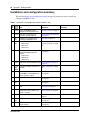
Installation and configuration summary
The table Installation and configuration checklist on page 10 provides the tasks to install and
configure a BCM450 system.
Table 1 Installation and configuration checklist (Sheet 1 of 2)
;
Task
Reference
5 min
Review the BCM450 system
hardware and configuration tools.
System overview on page 15
2 min
Verify that you have the tools,
materials, and data required.
Tools and system information
on page 12
15
min
Complete the checklists before
installing the BCM450 system.
Checklists on page 13
12
min
Install the BCM450 main unit:
• Rack-mount
• Wall-mount
• Desk-mount
Main unit and expansion
cabinet installation on page
19
9 min
(Optional)
Install the BCM450 expansion
cabinet:
• Rack-mount
• Wall-mount
• Desk-mount
Expansion cabinet installation
on page 23
3 min
Apply power to the BCM450 system. Power-supply connection on
page 24
1 min Configure the MBMs with Element
(per
Manager.
MBM)
MBM configuration on page
39
4 min
(Optional)
Install MBMs in the BCM450 main
unit or expansion cabinet.
Media bay module installation
on page 25
1 min
Connect the telephony connector.
Media bay module installation
on page 25
15
min
Connect the MBM wiring.
Media bay module installation
on page 25
5 min
Connect the BCM450 system to the
LAN.
BCM450 main unit LAN
connection on page 29
5 min
Determine DHCP server
configuration and IP address (use
default or change).
DHCP server configuration
and IP address on page 30
9 min
Install telephony hardware.
Telephone installation on
page 31
15
min
Download Element Manager.
BCM Web page downloads
on page 34
1 min
(Optional) Download the Startup
Profile template.
BCM Web page downloads
on page 34
NN40160-300
Comments
Chapter 1 Getting started
11
Table 1 Installation and configuration checklist (Sheet 2 of 2)
;
Task
Reference
Comments
10
min
Apply the keycode.
Software keycode on page 35
15
min
Configure the required BCM450
system parameters (Element
Manager or Startup Profile).
System parameters on page
35
N/A
(Optional) Complete the
configuration by customizing other
parameters.
Additional parameters on
page 40
Note: The stated times vary depending on the number and type of items installed.
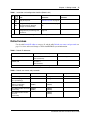
Default values
Use the table Default IP addresses on page 11 and the table Default user names and passwords on
page 11 to view and record changes to the default BCM450 system information.
Table 2 Default IP addresses
Port
IP address (subnet mask)
New IP address
OAM port (see Note)
10.10.11.1
(255.255.255.252)
Cannot be changed.
BCM450 LAN
192.168.2.2
(255.255.254.0)
Note: DHCP is enabled on the OAM port and assigns the following IP address: 10.10.11.2
Table 3 Default user names and passwords
Tool
User ID | User name
Password
Element Manager
nnadmin
PlsChgMe!
BCM450 Web page
(http:// [IP address])
nnadmin
PlsChgMe!
Telset Administration and
telephony configuration
(F9*8 and F**Config)
SETNNA
(738662)
CONFIG
(266344)
Telset Administration voice mail SETNNA
(Feature 983)
(738662)
CONFIG
(266344)
Telset Administration initialize
voice mail
(Feature 983)
–
New password
CONFIG
(266344)
Installation Checklist and Quick Start Guide
12
Chapter 1 Getting started
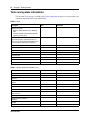
Tools and system information
Use the table Tools on page 12 and the table System information on page 12 to record values and
comments about tools and system information.
Table 4 Tools
Description
Value
Comments
Value
Comments
Laptop (or PC) with:
• Windows 2000, Windows XP, or Windows
Vista
• minimum 256 MB, recommended 512 MB
• 150 MB free disk space
Mounting hardware
rack-mount brackets, wall-mount bracket, or
rubber feet; an optional plywood backboard 3/4
in. (2 cm) thick for wall-mount installations
Phillips #2 screwdriver
Common screwdriver
Pliers
Antistatic ground strap
Connecting tool
25-pair cable with RJ-21 connector
Cat 5 Ethernet cable with RJ-45 connectors
Surge protector
Table 5 System information (Sheet 1 of 2)
Description
System name
Date and Time (NTP/Trunk/Manual)
Time zone
Initial IP address and netmask for each network
interface
Default next-hop router (default gateway)
DHCP server
DNS domain name
Primary (and optional secondary)
DNS servers IP
Profile/region
Telephony Startup template
(DID/PBX)
Start DN
Fractional T1 channel numbers
NN40160-300
Chapter 1 Getting started
13
Table 5 System information (Sheet 2 of 2)
Description
Value
Comments
Frame relay DLCI/CIR (if applicable)
SNMP agent (security, version)
SNMP manager IP address
SNMP community string
Checklists
Before installing the BCM450 hardware, complete the following checklists. For more information,
see Business Communications Manager 450 1.0 Installation—Hardware (NN40160-301).
General checklist
5 minutes
F Determine the location for the main unit (and optional expansion cabinet), telephones, and other
equipment based on spacing and electrical requirements.
F Order the required trunks from the central office.
F Ensure that you have all the equipment and supplies you need to install the system.
F Ensure that the system complies with the environmental requirements.
F Ensure that the system complies with the electrical requirements.
F Ensure that the system complies with the site telephony-wiring requirements.
Main unit components checklist
5 minutes
Check that you have the following components, and inspect the components for any damage:
F one main unit
F one power supply cable
F four rubber feet
F one cable tie
F a documentation CD
F Installation Checklist and Quick Start Guide
Installation Checklist and Quick Start Guide
14
Chapter 1 Getting started
Expansion cabinet and media bay modules components checklist
5 minutes
(optional)
Check that you have the following components, and inspect the components for any damage:
F one expansion cabinet
F one power supply cable
F one expansion cable (shielded Ethernet cable)
F four rubber feet
F the correct media bay modules (MBM)
NN40160-300
15
Chapter 2
System overview
You require the following hardware components and configuration tools to install and configure
your BCM450 system:
•
•
•
•
•
Main units on page 15
Expansion cabinets and media bay modules on page 16
Additional hardware on page 17
Nortel Business Element Manager on page 17
Startup Profile on page 17
For more information, see Nortel Business Communications Manager 450 1.0 Installation—
Hardware (NN40160-301).
Main units
The main hardware component in the BCM450 system is the main unit.
Standard main unit
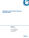
The table Main unit description on page 15 describes the standard main unit, and the figure Main
unit ports and connectors on page 16 shows a standard main unit.
Table 6 Main unit description
Standard main units
Description
BCM450 main unit (with
telephony only)
The BCM450 main unit provides call-processing and simple data networking
functions. It includes four media bay module (MBM) bays, and four connections for
auxiliary equipment (auxiliary ringer, page relay, page output, and music source) The
BCM450 main unit does not include a router, but it includes 3 LAN ports: one is the
OAM port for technicians, and the other two are for basic LAN connectivity.
Installation Checklist and Quick Start Guide
16
Chapter 2 System overview
Figure 1 Main unit ports and connectors
MBM bays
OAM port
LAN ports Music source
Auxiliary ringer Page relay
DS256 port
Page output
USB ports
Expansion cabinets and media bay modules
The BCM450 system can include an expansion cabinet. The expansion cabinet is designed to
accommodate up to six additional MBMs to connect additional telephony equipment to the
system. The MBMs connect with external devices to implement various trunks and stations.
The table Trunk, station, and combination MBMs on page 16 lists the trunk MBMs and station
MBMs that are supported on the main unit and expansion cabinet.
Table 7 Trunk, station, and combination MBMs
Trunk MBMs
Station MBMs
ADID4/ADID8
ASM8/ASM8+ (up to 2 on 4x16
the main unit, 4 on the
expansion cabinet)
BRIM
DSM16/DSM16+/
DSM32/DSM32+
DTM
GASM (up to 2 on the
main unit, 4 on the
expansion cabinet)
GATM4/GATM8
NN40160-300
Combination MBMs
G4x16/G8x16
Other
FEM (main unit only
Chapter 2 System overview
17
Additional hardware
In addition to the main unit, expansion unit, and MBMs, the BCM450 system includes the
additional hardware listed in the table BCM450 hardware descriptions on page 17.
Table 8 BCM450 hardware descriptions
Hardware
Description
Wall-mount bracket
A bracket designed for mounting a BCM450 unit (main unit or expansion unit) to a
wall.
Power supply adapter cord
The power-supply adapter cord is for international (non-North American) BCM450
users. It connects to the power supply on one end and to the (C-14) BCM450 power
bar on the other end.
You require one power-supply adapter cord for each power supply you want to
connect to the power bar.
Compact Expansion Card
(CEC)
An optional internal component that increases the capacity of the BCM450 system.
Uninterruptable power supply An uninterruptable power supply (UPS) is an optional device that maintains
(UPS)
continuous operation during power interruption or failure conditions. The UPS
provides power-source monitoring and battery-backup activation so that critical
(if applicable)
BCM450 functionality is maintained.
BCM450 supports American Power Conversion (APC) UPS devices that use a USB
control interface. The UPS control software configures various operational settings.
Nortel Business Element Manager
The primary management application for configuring and administering the BCM450 system is
Nortel Business Element Manager. Element Manager is a client-based management application
that runs on a Windows computer. With Element Manager, you can connect to the BCM450
system devices over an IP network and configure, administer, and monitor BCM450 system
devices.
You can use the latest Element Manager version to manage all previous BCM systems that use
Element Manager. You need only one instance of Element Manager on your computer.
The Element Manager requirements are:
•
•
•
Windows: Windows 2000, Windows XP, Windows Vista
RAM: minimum 256 MB, recommended 512 MB
free space: 150 MB
Element Manager access is also supported through a Citrix server.
Startup Profile
You can use the Startup Profile to customize a template with common BCM450 system
parameters. Then you can use this template to easily configure a single system or multiple systems.
Installation Checklist and Quick Start Guide
18
Chapter 2 System overview
You create the Startup Profile using the Startup Profile template (a Microsoft Excel template), and
then use a USB storage device to transfer the Startup Profile data to the BCM450 main unit.
Loading the Startup Profile adds about 5 minutes to the time for the BCM450 system to boot.
To use the Startup Profile template, you need:
•
•
•
•
a computer with a USB port
Microsoft Excel 2000 or later
the Nortel BCM450 Startup Profile template (Microsoft Excel template)
a portable USB storage device compatible with USB 1.1 or USB 2.0 (formatted for FAT32)
NN40160-300
19
Chapter 3
Hardware installation
See the following procedures to install the BCM450 hardware:
•
•
•
•
•
•
•
•
•
Main unit and expansion cabinet installation on page 19
Compact Expansion Card installation on page 22
Media bay module installation on page 25
Expansion cabinet installation on page 23
Power-supply connection on page 24
Media bay module installation on page 25
BCM450 main unit LAN connection on page 29
DHCP server configuration and IP address on page 30
Telephone installation on page 31
Main unit and expansion cabinet installation
You typically install the main unit and expansion cabinets in the same manner. Make sure you
install the expansion cabinets close enough to the main unit so you can connect the supplied 5 m
(16 ft) expansion cable between the expansion cabinet and main unit.
Nortel provides three methods of installing the BCM450 units:
•
•
•
rack-mount
wall-mount
desktop-mount
Caution: To keep the BCM450 system operating at the optimal internal temperature, keep
the top, sides, and rear clear of obstructions and away from the exhaust of other equipment.
Do not place any objects on top of a main unit.
For more information, see Nortel Business Communications Manager 450 1.0 Installation—
System (NN40160-301).
Rack-mount installation
You can install a BCM main unit in a standard 19-inch equipment rack along with your other
networking and telecommunications equipment. The BCM expansion cabinet installs in a similar
manner to the main units.
Installation Checklist and Quick Start Guide
20
Chapter 3 Hardware installation
Caution:
When you install the main unit in a rack, do not stack units directly on top of one another in the
rack.
Fasten each unit to the rack with the appropriate mounting brackets. Mounting brackets cannot
support multiple units.
For desk-mount installations, do not place anything directly on top of the BCM main unit.
Use the following procedures to install a BCM450 unit in a rack:
•
•
To attach the rack-mount brackets on page 20
To mount the main unit in an equipment rack on page 20
To attach the rack-mount brackets
5 minutes
1
Place the BCM main unit on a flat, clean surface.
2
Align the screw holes between the BCM450 main unit and the right rack-mount bracket.
3
Fasten the bracket to the BCM450 main unit using four screws.
Caution: Use only the screws supplied with the rack-mount bracket. Do not replace
the screws. Other screws can damage the unit.
4
Align the screw holes between the BCM450 main unit and the left rack-mount bracket.
5
Fasten the bracket to the main unit using four screws.
Note: The expansion cabinet rack-mount bracket has an additional set of holes so that
you can install the brackets so that the expansion cabinet sits flush with the BCM main
unit in an equipment rack.
To mount the main unit in an equipment rack
7 minutes
1
Determine the location in the rack where you want to install the main unit.
2
Position the main unit in the rack. Have an assistant hold the main unit.
3
Align the holes in the rack-mount bracket with the holes in the equipment rack rails.
4
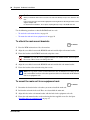
Fasten the rack-mount brackets to the rack using the four supplied screws See the figure
Attach the unit to an equipment rack on page 21.
NN40160-300
Chapter 3 Hardware installation
21
Figure 2 Attach the unit to an equipment rack
Wall-mount installation
To install a BCM450 unit (main unit or expansion cabinet) on a wall, you need a wall-mount
bracket for each unit.
Use the following procedures to install a BCM450 unit on a wall:
•
To install the BCM450 on a wall on page 21
To install the BCM450 on a wall
1
6 minutes
Place the wall-mount bracket on the backboard (or wall) and mark the location of the screw
holes. Use a bubble level to ensure that the wall-mount bracket is level with the plywood
backboard.
Note: If the backboard for the BCM main unit has enough room for the expansion
cabinet, you do not require a second backboard.
2
Install four #10 x 2.5 cm (#10 x 1 in.) round-head screws in the backboard. Leave
approximately 0.5 cm (0.25 in.) of each screw exposed from the backboard (or wall).
3
Hang the wall-mount bracket on the installed screws.
4
Use a level to ensure the wall-mount bracket is level.
5
Remove the wall-mount bracket from the backboard.
6
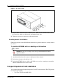
Align the screw holes on one side of the BCM450 main unit with the wall-mount bracket.
7
Fasten the wall-mount brackets securely to the BCM main unit using the screws provided.
Caution: Use only the screws supplied with the wall-mount bracket kit (NTAB3422).
Do not replace the screws. Other screws can damage the unit.
Installation Checklist and Quick Start Guide
22
Chapter 3 Hardware installation
Figure 3 Wall-mount bracket
8
Hang the BCM main unit on the backboard screws. Make sure the main unit is level. Ensure
the wood screw heads seat fully into the wall-mount bracket slots.
9
Tighten the wood screws against the wall-mount bracket.
Desktop-mount installation
Follow this procedure to install a BCM unit (main unit or expansion cabinet) on a desktop or other
flat surface.
To install a BCM450 unit on a desktop or flat surface
4 minutes
Caution: Do not place anything directly on top of the BCM450 main unit or
expansion cabinet.
1
Attach four rubber feet to the corners on the bottom of the main unit.
2
Position the main unit on the table or shelf.
3
Position the BCM450 unit on a table or shelf. Make sure you leave enough space around the
unit for ventilation and access to the cables.
Compact Expansion Card installation
You can install the optional Compact Expansion Card (CEC) in the main unit. The CEC provides
the following functionality:
•
NN40160-300
Up to Four TI C6424 600 MHz DSPs.
Chapter 3 Hardware installation
•
•
•
23
2MBx16 DDR2 for each DSPs
Process voice services up to 240 Digital Trunk gateways
Process up to 96 G.729 IP trunks per each CEC card
To install the CEC
5 minutes
1
Remove the Base Function Tray.
2
Remove the CEC faceplate (the right-most slot) by applying pressure to the bottom of the
faceplate from the inside of the Base Function tray. Once the bottom has come loose, remove
the faceplate from the front.
3
Screw the four metal standoffs (included) into the main board of the base function tray.
4
Slide the CEC into position from the back of the base function tray, so that the CEC protrudes
slightly from the front faceplate of the base function tray.
5
Align the connectors on the card and on the main board of the base function tray and push
down. Ensure that the card is connected securely to the main board.
6
Use the four supplied screws to fasten the card to the standoffs.
7
Reinstall the Base Function Tray.
Expansion cabinet installation
After installing an MBM, or MBMs, in the expansion cabinet, install the expansion cabinet in the
same manner as the main unit (in a rack, on a wall, or on a flat surface).
For more information, see Nortel Business Communications Manager 450 1.0 Installation—
System (NN40160-301).
Warning: The timing in the BCM system is critical. Use the correct length cable as
supplied with the expansion cabinet. The system will not work properly if you connect
the BCM expansion cabinet using a cable that varies in length.
To install an expansion unit
9 minutes
1
Mount the expansion unit the same way as the main unit. Refer to Main unit and expansion
cabinet installation on page 19.
2
Locate the DS256 cable (NTAB3086) that was supplied with the expansion unit.
3
Plug one end of the DS256 cable into the DS256 port on the expansion unit.
4
Plug the other end of the cable into the DS256 connector on the faceplate of the BCM450 main
unit
Refer to the figure How to connect an expansion cabinet to a main unit on page 24.
Installation Checklist and Quick Start Guide
24
Chapter 3 Hardware installation
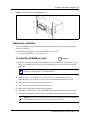
Figure 4 How to connect an expansion cabinet to a main unit
Main unit
Expansion cabinet
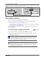
Power-supply connection
Use the power-supply cable supplied with each BCM450 unit.
Connect the power supply to your BCM450 system by one of the following methods:
•
•
To connect the power supply without a UPS on page 24
“To connect the power supply using a UPS” – see Nortel Business Communications Manager
450 1.0 Installation—System (NN40160-301).
For more information, see Nortel Business Communications Manager 450 1.0 Installation—
System (NN40160-301).
To connect the power supply without a UPS
3 minutes
1
Plug one end of the power-supply cable into the BCM450 power supply.
2
Plug the other end of the power-supply cable into the AC power source (wall outlet).
The BCM450 system boots.
Note: To use the Startup Profile for initial configuration of the BCM450 system,
save the Startup Profile on your USB storage device, and insert the USB storage
device in the USB port of the main unit before connecting the power. See To
download the Startup Profile template on page 34.
Warning: Leakage currents
You must reconnect the power cords to a grounded outlet before connecting the
telephony and data networking cables.
NN40160-300
Chapter 3 Hardware installation
25
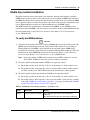
Media bay module installation
Install the expansion in the same manner as the main unit, and then install media bay modules
(MBM) in the expansion cabinet or the main unit. If you are installing the MBM in the main unit,
the MBM dip switches must remain in their default factory position. If you are installing the MBM
in the expansion cabinet, you must change them to the correct setting for your configuration. You
can use Element Manager to make any required modifications to the MBM settings.
The BCM450 main unit accommodates a maximum of four MBMs. If your BCM450 system
requires more than four MBMs, you must connect an expansion cabinet to the BCM450 main unit.
For more information, see Nortel Business Communications Manager 450 1.0 Installation—
System (NN40160-301).
To verify the MBM switches
2 minutes
1
Verify that the 6-pin dip switch is set to on for all MBMs that have the 6-pin dip switch, if the
MBM is being installed in the main unit. Verify that the DIP switches are set according to
Element Manager if the MBM is being installed in the expansion cabinet. MBMs being
installed in the expansion cabinet must first be configured through Element Manager. For more
information on setting MBM DIP switches for the expansion cabinet, see Nortel Business
Communications Manager 450 1.0 Installation—System (NN40160-301).
Note: If you are installing an FEM in the main unit, ensure all DIP switches are set to on.
All six LEDs should be lit when the system is returned to operation.
2
3
To install a global analog trunk module (GATM) in an expansion cabinet:
a
For the dip switches on the left side, at the rear of the module, set all the switches to on.
b
For the dip switches on the right side, at the rear of the module (country profile switches),
set all the switches to off. The GATM automatically downloads the country profiles.
To install a global analog station module 8 (GASM8) in an expansion cabinet:
a
For the dip switches on the left side, at the rear of the module, set all the switches to on.
b
For the dip switches on the right side, at the rear of the module, set the switches according
to the table GASM8 dip switch settings (switches 1–3) on page 25 and the table GASM8
regional dip switch settings (switches 4–8) on page 26.
Table 9 GASM8 dip switch settings (switches 1–3) (Sheet 1 of 2)
Switch
Description
Setting
Switch 1
Firmware download capability
OFF—Standard mode (firmware downloading not
supported)
ON—Enhanced mode (firmware downloading supported)
Installation Checklist and Quick Start Guide
26
Chapter 3 Hardware installation
Table 9 GASM8 dip switch settings (switches 1–3) (Sheet 2 of 2)
Switch
Description
Setting
Switch 2
To download the firmware from OFF—if you want the GASM8 to download the firmware
when the firmware version in the BCM450 is different than
the BCM450 (for enhanced
mode only)
the version in the GASM8 (default)
ON—if you want the GASM8 to download the firmware in
the event of a BCM450 cold start
Switch 3
Enable/disable echo
cancellation
OFF—Enables echo cancellation (default)
ON—Disables echo cancellation
Table 10 GASM8 regional dip switch settings (switches 4–8)
Switches 4 to 8 select the region for the GASM8 as follows:
Switch 4
Switch 5
Switch 6
Switch 7
Switch 8
North America
OFF
OFF
OFF
OFF
OFF
United Kingdom
OFF
OFF
OFF
OFF
ON
Australia
OFF
OFF
OFF
ON
OFF
Poland
OFF
OFF
OFF
ON
ON
Note: When switch 1 is ON (enhanced mode), an available regional profile will be downloaded and override
the regional dip switch settings.
To install an MBM
1 minute
1
Attach one end of a grounding strap to your wrist and the other end to a grounded metal
surface.
2
With the face of the MBM toward you, insert the MBM into an available MBM bay on the
main unit or the expansion cabinet.
3
Push the MBM completely into the MBM bay. You hear a click when the MBM is firmly
seated in the bay.
4
Repeat steps 2 and 3 for each additional MBM you wish to install.
The MBM must be configured for it to function. For information about configuring an MBM,
see To configure the MBMs on page 39. If installing a GASM module into the main unit
or expansion cabinet, you must reboot the BCM450 system for the module to function
properly. If you are installing an MBM in the main unit, the MBM must be installed
before it can be configured. If you are installing an MBM in the expansion cabinet,
configure it first, then install it in the appropriate MBM bay.
MBM wiring
15 minutes
Telephone lines connect to the expansion unit through the connectors on the MBM.
NN40160-300
Chapter 3 Hardware installation
27
For more information, see Nortel Business Communications Manager 450 1.0 Installation—
System (NN40160-301)
Danger: Electrical shock hazards
Electrical shock hazards from the telecommunications network and ac mains are possible
with this equipment. To minimize risk to service personnel and users, the BCM450 system
must be connected to an outlet with a third-wire ground. In addition, install blank
faceplates in all unused slots. The covers on all units must be in place at the completion of
any servicing.
Warning: Electrical shock warning
The MBMs were safety approved for installation into the expansion unit. The installer and
user are responsible for ensuring that installation of the hardware does not compromise
existing safety approvals.
BEFORE YOU OPEN the main unit or expansion unit, unplug the network
telecommunication cables and disconnect the unit from the ac power source.
Station modules: Connect the ports on these modules only to approved digital telephones
and peripherals with the proper cables on a protected internal wiring system.
Do not connect any telephones to wiring that runs outside the building.
Read and follow the installation instructions carefully.
Warning: Use only qualified persons to service the system.
The installation and service of this unit must be performed by service personnel with the
appropriate training and experience. Service personnel must be aware of the hazards of
working with telephony equipment and wiring. They must be experienced in techniques
that minimize any danger of shock or equipment damage.
Leakage currents
Service personnel must be alert to the possibility of high leakage currents becoming
available on metal system surfaces during power-line fault events on network lines. These
leakage currents normally flow safely to protective earth ground through the power cord.
However, if the ac power is unplugged prior to disconnecting the cables from the BCM450
units, this hazard can occur.
System shutdown: You must disconnect the telephony and data networking cables from
the system before disconnecting the power cord from a grounded outlet.
System startup: You must reconnect the power cords to a grounded outlet before
reconnecting the telephony and data-networking cables.
Installation Checklist and Quick Start Guide
28
Chapter 3 Hardware installation
To connect telephone lines to DTM, BRIM, or 4x16 MBMs
1
Obtain a telephone cable with a modular plug that matches the MBM to which you are
connecting:
•
•
•
RJ-48C—for DTM
RJ-45—for BRIM
RJ-11—for 4x16
2
Plug the modular cable into the jack in the front of the MBM.
3
Connect the other end of the cable to the telephone company demarcation blocks of the
building.
4
To connect telephone lines to another MBM, repeat steps 1 to 3 to for each additional line.
Warning: If the network ISDN is a U-loop, the BRIM must be connected only to an
NT1 provided by the service provider. The NT1 must provide a Telecommunication
Network Voltage (TNV) to Safety Extra Low Voltage (SELV) barrier.
Note: Do not attempt to plug digital equipment into the auxiliary (AUX) jacks on the
front of 4x16 MBM.
5
Select the appropriate option for your system:
•
•
If your system includes a 4x16 MBM, go to Connect extensions to the expansion unit on
page 29 for instruction about wiring the extensions for this MBM.
Repeat this procedure to add more telephone lines or proceed to Connect extensions to the
expansion unit on page 29 to add extensions.
To connect analog telephone lines to the GATM4, GATM8, G4x16,
or G8x16
1
Obtain a 25-pair cable with an RJ-21 connector on one end.
2
Plug the RJ-21 connector of the cable into the RJ-21 connector on the front of the MBM.
Use the lower RJ-21 connector on the G4x16 and G8x16 MBMs to connect analog lines.
3
Select the appropriate option to secure the RJ-21 connector to the MBM:
•
•
4
With a straight RJ-21 connector, use the two supplied screws on the sides of the connector
to secure it.
With a right-angle RJ-21 connector, use the supplied screw on the left side of the
connector to secure the left side of the connector. To secure the right side of the connector,
use the supplied cable tie to fasten the 25-pair cable to the anchor on the MBM.
Connect the other end of the cable to the telephone company demarcation blocks of the
building.
NN40160-300
Chapter 3 Hardware installation
29
Connect extensions to the expansion unit
Extensions connect to the expansion unit through the connectors on the MBM installed in the
expansion unit.
To connect extensions to DSM16, DSM32, ASM8, 4x16, G4x16, or
G8x16 MBMs
1
Obtain a 25-pair cable with an RJ-21 connector on one end.
2
Plug the RJ-21 connector of the cable into the RJ-21 connector on the front of the MBM.
Use the upper RJ-21 connector on the G4x16 and G8x16 MBMs to connect digital extensions.
3
Select the appropriate option to secure the RJ-21 connector to the MBM:
•
•
With a straight RJ-21 connector, use the two supplied screws on the sides of the connector
to secure it.
With a right-angle RJ-21 connector, use the supplied screw on the left side of the
connector to secure the left side of the connector. To secure the right side of the connector,
use the supplied cable tie to fasten the 25-pair cable to the anchor on the MBM.
4
Connect the other end of the cable to the local connecting blocks.
5
To connect extensions to a DSM32, repeat steps 1 to 4 for the second RJ-21 connector.
BCM450 main unit LAN connection
For more information, see Nortel Business Communications Manager 450 1.0 Installation—
System (NN40160-301).
Warning: The DHCP server on the main unit is enabled (IP Phones only) by
default. If your network already contains a DHCP server, disable the DHCP server
on the main unit.
To connect a BCM450 system to the LAN
5 minutes
1
Connect one end of a standard Ethernet cable to your LAN.
2
Plug the other end of the Ethernet cable into the LAN port on the BCM450 main unit.
3
If you want to use the internal BCM450 network switch to connect another IP device to the
LAN, connect an Ethernet cable between the IP device and one of the additional LAN ports on
the BCM450 system.
If you wish to connect more than one device to the BCM450 main unit, you must connect a Layer
2 switch using the procedure above. After the Layer 2 device is connected, connect the devices to
the BCM450 through the Layer 2 switch.
Installation Checklist and Quick Start Guide
30
Chapter 3 Hardware installation
If you cannot connect your BCM450 system to the LAN, you can access the system by connecting
through the OAM port. See To connect to the system using the OAM port on page 33.
DHCP server configuration and IP address
By default, the main unit is configured with a dynamic IP address, which means the unit requests
an IP configuration from a DHCP server.
The BCM450 main unit can have two DHCP server configurations:
•
•
If an external DHCP server is not present on page 30
If an external DHCP server is present on page 30
For more information, see Nortel Business Communications Manager 450 1.0 Installation—System
(NN40160-301).
If an external DHCP server is not present
If an external DHCP server is not present, the main unit uses the following default IP
configuration:
IP address:
192.168.2.2
Subnet mask:
255.255.254.0
Gateway:
192.168.1.1
The DHCP server on the main unit supplies IP configuration information for all IP devices (PCs
and IP Phones). It also supplies specific connection information to the IP Phones.
If an external DHCP server is present
Warning: The DHCP server on the main unit is enabled by default. If your
network already contains a DHCP server, disable the DHCP server on the main
unit.
If an external DHCP is present, the BCM450 system uses the IP configuration supplied by the
external DHCP server.
In this case, the DHCP server on the main unit supplies only IP Phones with IP configuration
information. It does not supply any other devices with IP settings. This means that the
administrator does not need to set up the external DHCP server to supply configuration settings to
the IP Phones.
The DHCP server on the main unit must configure a range of IP addresses to supply to the
IP Phones.
For example:
NN40160-300
Chapter 3 Hardware installation
31
If the external DHCP server supplies the IP address 177.218.21.45 (subnet mask is 255.255.255.0)
to the BCM450, the BCM450 DHCP server reserves the range 177.218.21.200–177.218.21.254.
You can use Element Manager to verify and change this default range.
The administrator must ensure that this range agrees with the network configuration. The range is
not used by the external DHCP server.
Telephone installation
The BCM450 system supports many types of telephony devices (telephones). For more
information about the supported telephones, see Nortel Business Communications Manager 450
1.0 Installation—Devices (NN40160-302).
For more information about installing telephones, Nortel Business Communications Manager 450 1.0
Installation—System (NN40160-301).
To install telephones
1
9 minutes/telephone
Open the box for each telephone, and verify that you have the following components:
•
•
•
•
telephone set
power supply and power-supply cable (if applicable)
telephone cable
installation instructions
2
Visually inspect the components for any damage.
3
Install the telephones as shown in the included installation instructions.
4
Label the telephone with customer-supplied information. Note the location, wall-jack
identifier, and phone number for punch downs and BCM450 software commissioning.
Installation Checklist and Quick Start Guide
32
Chapter 3 Hardware installation
NN40160-300
33
Chapter 4
System configuration
The initial configuration defines your BCM450 system to the network. It also gives the system a
unique identity and initial parameters. Then you can continue with the specific configurations for
your system.
This chapter provides information on the following topics:
•
•
•
•
•
•
•
Connect to the system on page 33
BCM Web page downloads on page 34
Software keycode on page 35
System parameters on page 35
DHCP server configuration on page 39
MBM configuration on page 39
Additional parameters on page 40
For more information about installing the BCM450 system (such as wiring charts and cable
diagrams), see Nortel Business Communications Manager 450 1.0 Installation—Hardware
(NN40160-301).
Connect to the system
If you can use the default IP address, you can connect the BCM450 system to the LAN. Then you
can configure the BCM450 system, through Element Manager, from any PC connected to the
LAN.
If you can connect through a LAN connection, proceed to BCM Web page downloads on page 34.
Warning: Before using the default address on your network, check with your system
administrator. If this address conflicts with the LAN settings, you can cause network
damage if you connect to the network without changing the IP address.
If you must change the IP address (due to a conflict with your network), you can connect to the
BCM450 through the OAM port. See To connect to the system using the OAM port on page 33.
For more information, see Nortel Business Communications Manager 450 1.0 Installation—Hardware
(NN40160-301).
To connect to the system using the OAM port
1
Connect one end of the Ethernet cable to the OAM port on the main unit.
2
Connect the other end of the Ethernet cable to the Ethernet port on your computer.
The DHCP-enabled computer is assigned IP address 10.10.11.2 (255.255.255.252).
Installation Checklist and Quick Start Guide
34
Chapter 4 System configuration
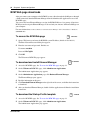
BCM Web page downloads
After you connect your computer to the BCM450 system, either through the OAM port or through
a LAN connection, download Element Manager from the Administrator Applications area of the
BCM Web page.
You can use the latest Element Manager version (for BCM450 Release 1) to manage all previous
BCM systems that require Element Manager. You need only one instance of Element Manager on
your computer.
For more information, see Nortel Business Communications Manager 450 1.0 Installation—Hardware
(NN40160-301).
To access the BCM Web page
1
2 minutes
Open a Web browser and enter the BCM450 system IP address (default is 192.168.2.2).
The Enter Network Password dialog box appears.
2
Enter the username and password. Defaults are:
Username: nnadmin
Password: PlsChgMe!
3
Click OK.
The Welcome to BCM Web page appears.
To download and install Element Manager
1
Access the BCM Web page. See To access the BCM Web page on page 34.
2
On the Welcome to BCM Web page, click Administrator Applications.
15 minutes
The Administrator Applications page appears.
3
On the Administrator Applications page, click Business Element Manager.
The Element Manager pane appears.
4
Read the information on this pane.
5
Click Download Element Manager on the right side of the screen, and follow the instructions
to download.
6
After you download Element Manager, double-click the application and follow the installation
instructions.
To download the Startup Profile template
1
Access the BCM Web page. See To access the BCM Web page on page 34.
2
On the Welcome to BCM Web page, click Administrator Applications.
The Administrator Applications page appears.
NN40160-300
1 minute
Chapter 4 System configuration
3
35
On the Administrator Applications page, click Startup Profile template.
The Startup Profile template pane appears.
4
Read the information on this pane.
5
Click Download Startup Profile template on the right side of the screen, and follow the
instructions to download.
Software keycode
You require a keycode to enable software features on your BCM450 system. You receive only one
keycode whether you purchase one feature or a bundle of features. You can load a keycode using
Element Manager, Startup Profile, or Telset Administration.
To generate a keycode, you require an authorization code for each feature you purchase.
For example, if you require one feature, you receive one authorization code and you generate one
keycode. If you purchase four features, you receive four authorization codes, but you generate
only one keycode.
To generate a keycode through the Nortel Keycode Retrieval System (KRS), you require:
•
•
•
Username and password for the KRS (http://www.nortel.com/servsup/krs)
BCM450 authorization code for each feature
BCM450 system ID
For more information about keycodes, see Keycode Install Guide (NN40010-301).
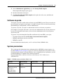
System parameters
This section provides information about configuring the basic BCM450 system parameters (see
the table BCM450 system parameters on page 35). You can configure the basic parameters using
the Startup Profile template or Element Manager. After configuring the basic parameters, you can
use Element Manager to configure more advanced parameters.
For more information, see Business Communications Manager 450 1.0 Maintenance
(NN40160-503).
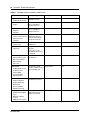
Table 11 BCM450 system parameters (Sheet 1 of 3)
Parameters
Element Manager
Startup Profile
Telset Administration
Keycode
Configuration > System >
Keycodes
Keycode
Feature 9*8 > Feature codes
IP address:
• Obtain dynamically
• IP address
• IP subnet mask
• Default gateway
Configuration > System >
IP Subsystem
IP Address
Feature 9*8 > IP Address
Installation Checklist and Quick Start Guide
36
Chapter 4 System configuration
Table 11 BCM450 system parameters (Sheet 2 of 3)
Parameters
Element Manager
Modem:
• Enable/disable modem
Configuration > Resources Modem
> Dial Up Interfaces
Feature 9*8 > Modem
System:
• Region
Administration > Utilities >
Reset > Cold Reset
Telephony Services
System
Feature **PROFILE
Telephony startup:
• Template
• Start DN
Administration > Utilities >
Reset > Cold Reset
Telephony Services
Telephony Startup
Feature **STARTUP
User account:
• Telset user ID (numeric)
• Telset password
(numeric)
Configuration >
Administrator Access >
Accounts and Privileges >
View by Accounts tab
UserAccount
Feature 9*8 > User Accounts
System:
• System name
Configuration > System >
Identification
System
N/A
System:
• System ID
Configuration > System >
Keycodes
(System ID - it is set
automatically and cannot
be changed)
System
N/A
Time:
• Date and Time source
• NTP server address
• Date and time
• Time zone
Configuration > System >
Date and Time
Time
N/A
DHCP server:
• Enable/disable server
• IP domain name
• Primary DNS
• Secondary DNS
• Default gateway
DHCP Server
Configuration > Data
Services > DHCP Server >
General Settings tab
N/A
IP Phones:
• Enable registration
• Enable global pwd
• Global pwd
• Auto-assign DNs
• Advertisement logo
Configuration > Resources IP Telephones
> Telephony Resources
N/A
SNMP Agent:
• Enable/disable SNMP
agent
• Minimum required
security
• SNMP version support
Configuration >
Administrator Access >
SNMP > General tab
NN40160-300
Startup Profile
SNMP Agent
Telset Administration
N/A
Chapter 4 System configuration
37
Table 11 BCM450 system parameters (Sheet 3 of 3)
Parameters
Element Manager
Startup Profile
Telset Administration
SNMP community:
• Community string
• Type of access
Configuration >
Administrator Access >
SNMP > Community
Strings tab
SNMP Community
N/A
SNMP manager:
• Manager IP address
Configuration >
Administrator Access >
SNMP > General tab
SNMP Manager
N/A
User account:
• User ID
• Group
• Description
• Callback number
Configuration >
Administrator Access >
Accounts and Privileges >
View by Accounts tab
User Account
N/A
To configure the system using Element Manager
15 minutes
1
Open Element Manager.
2
In the Element Navigation Panel, select Network Elements, New Network Element, and
then select Business Communications Manager.
3
Enter the BCM450 system IP address in the dialog box (default is 192.168.2.2).
4
Enter the following username and password:
Username: nnadmin
Password: PlsChgMe!
5
Click Ok.
6
In the Element Navigation Panel, expand the Network Elements folder. Click on the IP
address of the BCM that you wish to connect to.
7
The Connection Information page will load. Enter the User ID and Password.
8
Click Connect on the menu bar.
Element Manager connects to the BCM450 system.
9
Configure the required parameters. See the table BCM450 system parameters on page 35.
For more information about configuring the system, see the online Help within
Element Manager.
Installation Checklist and Quick Start Guide
38
Chapter 4 System configuration
To configure the system using the Startup Profile (optional)
15 minutes
Note: The Startup Profile template uses macros to perform certain functions. You
must set your Excel macro security level to medium or low to enable the macros:
• From the Tools menu, select Macros and then select Security.
• Select Medium or Low.
• Exit from Excel.
• Open the Startup Profile template (in Excel).
• Enable macros if prompted.
1
On a computer with a USB port and Microsoft Excel, open the Startup Profile template.
If you do not have a copy of the Startup Profile template, see To download the Startup Profile
template on page 34.
2
Refer to the Usage Instructions tab for instructions about using the Startup Profile template.
3
Click the StartupProfileTemplate tab to begin entering information in the Startup Profile
template.
4
In the Startup Profile template, enter your BCM450 system ID in the System ID field.
The system ID is on the box of the main unit and on the main unit itself. If you enter the wrong
system ID, the Startup Profile does not function with your system.
5
Click the large button at the top of the Startup Profile template to save a version of the Startup
Profile (.sps file) and a version of the Startup Profile editor (Excel spreadsheet) on your
computer.
The filenames for the Startup Profile editor and the Startup Profile consist of the system ID
followed by the appropriate extension.
Note: Never edit the Startup Profile (.sps file) directly; always use the Startup
Profile editor to make changes.
6
In the Startup Profile editor, enter the remaining information that you want loaded onto the
BCM450 system.
The Startup Profile editor contains explanations of the various parameters. Click the cell where
you want to enter information, and the Help text appears.
You can specify which parameters to load onto your system by selecting Apply for the
parameters you want to load. If you do not want to load certain parameters, select Ignore.
7
After you enter all the information, click the large button at the top of the Startup Profile
template to save a version of the Startup Profile (.sps file) and a version of the Startup Profile
editor (Excel spreadsheet) on your computer.
8
Exit from Microsoft Excel.
NN40160-300
Chapter 4 System configuration
9
39
Insert the USB storage device into the bottom USB port of the computer.
10 Copy the Startup Profile (.sps file) to the root directory of the USB storage device.
11 If you want to load your keycode using the Startup Profile, copy the keycode file to the root
directory of the USB storage device.
The name of the keycode file on the USB storage device must exactly match the filename you
entered in the Startup Profile editor.
12 Remove the USB storage device from the USB port of the computer.
The Startup Profile is now stored on the USB storage device.
13 Insert the USB storage device into the USB port of the BCM450 main unit before you power
up the system.
Warning: Do not use the Startup Profile on a functional BCM450 system
because the parameter values in the Startup Profile replace those on the system.
For more information about the Startup Profile, see the Business Communications Manager 450
1.0 Maintenance (NN40160-503) or Business Communications Manager 450 1.0 Installation—
Hardware (NN40160-301).
DHCP server configuration
Use the following procedure to configure DHCP server settings for your system.
To configure DHCP server settings
5 minutes
1
From the Configuration tab, click the Data Services folder to expand it.
2
Select DHCP Server.
3
Select the General Settings tab.
4
Configure the attributes for your system.
MBM configuration
You must configure the MBMs to function with your BCM450 system.
For more information, see Business Communications Manager 450 1.0 Maintenance
(NN40160-503) or Business Communications Manager 450 1.0 Installation—Hardware
(NN40160-301).
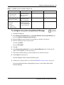
To configure the MBMs
1 minute/MBM
1
Open Element Manager and connect to your BCM450 system.
2
From the Configuration tab, click the Resources folder to expand it.
Installation Checklist and Quick Start Guide
40
Chapter 4 System configuration
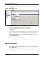
3
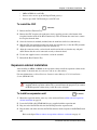
Select Telephony Resources from the Resources folder. See the figure Telephony Resources
page on page 40.
Figure 5 Telephony Resources page
4
In the Modules section, select the row of the MBM that you want to configure.
5
Double-click the Module type field to display the list of MBM types.
6
Select the type of MBM that you installed in the expansion cabinet.
7
Click Configure.
8
Enter the Start DN, Public Received Digits/OLI, Private Received Digits/OLI, Start Line
(depending on MBM type) and select Assign Target Lines check box if required (default is
clear).
9
If you are installing an MBM in the expansion cabinet, the suggested DIP switch settings
appear in the DIP switch field.
10 Repeat steps 4 to 9 to enable the second MBM.
You can set other parameters for the MBMs depending on the type of MBM you
installed.
Additional parameters
You can also customize the following parameters:
•
•
•
Security policies—see Nortel Business Communications Manager 450 1.0 Administration and
Security (NN40160-601)
Modem settings—see the Networking Configuration Guide
Software updates—see Nortel Business Communications Manager 450 1.0 Administration and
Security (NN40160-601)
NN40160-300
Chapter 4 System configuration
•
•
41
Voice mail—for information about using the Web-based interface to configure your voice mail
system, see the CallPilot Manager Set Up and Operation Guide (NN40090-300); or for
information about using Telset Administration to configure your voice mail system, see the
CallPilot Telephone Administration Guide (NN40090-500)
Backup and restore—see Nortel Business Communications Manager 450 1.0 Administration
and Security (NN40160-601)
Installation Checklist and Quick Start Guide
42
Chapter 4 System configuration
NN40160-300