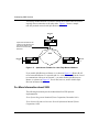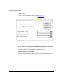
1
Configuring XNS Services
Router Software Version 10.0
Site Manager Software Version 4.0
Part No. 112949 Rev. A
January 1996
4401 Great America Parkway
Santa Clara, CA 95054
8 Federal Street
Billerica, MA 01821
Copyright © 1988–1996 Bay Networks, Inc.
All rights reserved. Printed in the USA. January 1996.
The information in this document is subject to change without notice. The statements, configurations, technical data, and
recommendations in this document are believed to be accurate and reliable, but are presented without express or implied
warranty. Users must take full responsibility for their applications of any products specified in this document. The
information in this document is proprietary to Bay Networks, Inc.
The software described in this document is furnished under a license agreement and may only be used in accordance with the
terms of that license. A summary of the Software License is included in this document.
Restricted Rights Legend
Use, duplication, or disclosure by the United States Government is subject to restrictions as set forth in subparagraph
(c)(1)(ii) of the Rights in Technical Data and Computer Software clause at DFARS 252.227-7013.
Notice for All Other Executive Agencies
Notwithstanding any other license agreement that may pertain to, or accompany the delivery of, this computer software, the
rights of the United States Government regarding its use, reproduction, and disclosure are as set forth in the Commercial
Computer Software-Restricted Rights clause at FAR 52.227-19.
Trademarks of Bay Networks, Inc.
ACE, AFN, BCN, BLN, BN, CN, FRE, LN, Optivity, SynOptics, SynOptics Communications, Wellfleet and the Wellfleet
logo are registered trademarks and AN, ANH, ASN, BaySIS, BayStack, BCNX, BLNX, BNX, EZ Internetwork, EZ LAN,
FN, PathMan, PhonePlus, PPX, Quick2Config, RouterMan, SPEX, Bay Networks, Bay Networks Press, the Bay Networks
logo and the SynOptics logo are trademarks of Bay Networks, Inc.
Third-Party Trademarks
All other trademarks and registered trademarks are the property of their respective owners.
Statement of Conditions
In the interest of improving internal design, operational function, and/or reliability, Bay Networks, Inc. reserves the right to
make changes to the products described in this document without notice.
Bay Networks, Inc. does not assume any liability that may occur due to the use or application of the product(s) or circuit
layout(s) described herein.
Portions of the code in this software product are Copyright © 1988, Regents of the University of California. All rights
reserved. Redistribution and use in source and binary forms of such portions are permitted, provided that the above copyright
notice and this paragraph are duplicated in all such forms and that any documentation, advertising materials, and other
materials related to such distribution and use acknowledge that such portions of the software were developed by the
University of California, Berkeley. The name of the University may not be used to endorse or promote products derived from
such portions of the software without specific prior written permission.
SUCH PORTIONS OF THE SOFTWARE ARE PROVIDED “AS IS” AND WITHOUT ANY EXPRESS OR IMPLIED
WARRANTIES, INCLUDING, WITHOUT LIMITATION, THE IMPLIED WARRANTIES OF MERCHANTABILITY
AND FITNESS FOR A PARTICULAR PURPOSE.
In addition, the program and information contained herein are licensed only pursuant to a license agreement that contains
restrictions on use and disclosure (that may incorporate by reference certain limitations and notices imposed by third parties).
Bay Networks Software License
Note: This is Bay Networks basic license document. In the absence of a
software license agreement specifying varying terms, this license — or the
license included with the particular product — shall govern licensee’s use of
Bay Networks software.
This Software License shall govern the licensing of all software provided to licensee by Bay Networks (“Software”).
Bay Networks will provide licensee with Software in machine-readable form and related documentation
(“Documentation”). The Software provided under this license is proprietary to Bay Networks and to third parties from
whom Bay Networks has acquired license rights. Bay Networks will not grant any Software license whatsoever, either
explicitly or implicitly, except by acceptance of an order for either Software or for a Bay Networks product
(“Equipment”) that is packaged with Software. Each such license is subject to the following restrictions:
1.
Upon delivery of the Software, Bay Networks grants to licensee a personal, nontransferable, nonexclusive license
to use the Software with the Equipment with which or for which it was originally acquired, including use at any
of licensee’s facilities to which the Equipment may be transferred, for the useful life of the Equipment unless
earlier terminated by default or cancellation. Use of the Software shall be limited to such Equipment and to such
facility. Software which is licensed for use on hardware not offered by Bay Networks is not subject to restricted
use on any Equipment, however, unless otherwise specified on the Documentation, each licensed copy of such
Software may only be installed on one hardware item at any time.
2.
Licensee may use the Software with backup Equipment only if the Equipment with which or for which it was
acquired is inoperative.
3.
Licensee may make a single copy of the Software (but not firmware) for safekeeping (archives) or backup
purposes.
4.
Licensee may modify Software (but not firmware), or combine it with other software, subject to the provision
that those portions of the resulting software which incorporate Software are subject to the restrictions of this
license. Licensee shall not make the resulting software available for use by any third party.
5.
Neither title nor ownership to Software passes to licensee.
6.
Licensee shall not provide, or otherwise make available, any Software, in whole or in part, in any form, to any
third party. Third parties do not include consultants, subcontractors, or agents of licensee who have licensee’s
permission to use the Software at licensee’s facility, and who have agreed in writing to use the Software only in
accordance with the restrictions of this license.
7.
Third-party owners from whom Bay Networks has acquired license rights to software that is incorporated into
Bay Networks products shall have the right to enforce the provisions of this license against licensee.
8.
Licensee shall not remove or obscure any copyright, patent, trademark, trade secret, or similar intellectual
property or restricted rights notice within or affixed to any Software and shall reproduce and affix such notice on
any backup copy of Software or copies of software resulting from modification or combination performed by
licensee as permitted by this license.
Bay Networks, Inc.
4401 Great America Parkway, Santa Clara, CA 95054
8 Federal Street, Billerica, MA 01821
Bay Networks Software License (continued)
9.
Licensee shall not reverse assemble, reverse compile, or in any way reverse engineer the Software. [Note: For
licensees in the European Community, the Software Directive dated 14 May 1991 (as may be amended from time
to time) shall apply for interoperability purposes. Licensee must notify Bay Networks in writing of any such
intended examination of the Software and Bay Networks may provide review and assistance.]
10. Notwithstanding any foregoing terms to the contrary, if licensee licenses the Bay Networks product “Site
Manager,” licensee may duplicate and install the Site Manager product as specified in the Documentation. This
right is granted solely as necessary for use of Site Manager on hardware installed with licensee’s network.
11. This license will automatically terminate upon improper handling of Software, such as by disclosure, or Bay
Networks may terminate this license by written notice to licensee if licensee fails to comply with any of the
material provisions of this license and fails to cure such failure within thirty (30) days after the receipt of written
notice from Bay Networks. Upon termination of this license, licensee shall discontinue all use of the Software
and return the Software and Documentation, including all copies, to Bay Networks.
12. Licensee’s obligations under this license shall survive expiration or termination of this license.
Bay Networks, Inc.
4401 Great America Parkway, Santa Clara, CA 95054
8 Federal Street, Billerica, MA 01821
Contents
About This Guide
Audience ........................................................................................................................... xi
Before You Begin .............................................................................................................. xi
Bay Networks Customer Support .....................................................................................xii
CompuServe ..............................................................................................................xii
InfoFACTS .................................................................................................................xiii
World Wide Web ........................................................................................................xiii
How to Get Help ..............................................................................................................xiii
Conventions .....................................................................................................................xiv
Ordering Bay Networks Publications ............................................................................... xv
Acronyms ......................................................................................................................... xv
Chapter 1
XNS Overview
XNS Protocol Stack ........................................................................................................1-2
Protocol Layer/Level Support .........................................................................................1-3
Level 0 ......................................................................................................................1-3
Level 1 ......................................................................................................................1-4
Level 2 ......................................................................................................................1-4
XNS RIP Overview .........................................................................................................1-4
Error Protocol .................................................................................................................1-6
Echo Protocol .................................................................................................................1-7
Sequenced Packet Protocol ...........................................................................................1-8
Packet Exchange Protocol ..............................................................................................1-8
External Servers .............................................................................................................1-8
Static Routes ..................................................................................................................1-9
Adjacent Hosts .............................................................................................................1-11
Configurable Split Horizon ............................................................................................1-13
For More Information about XNS ..................................................................................1-14
v
Chapter 2
XNS Configuration Notes
Configuring XNS without RIP .........................................................................................2-1
Configuring a MAC Address on a Token Ring Interface .................................................2-2
Chapter 3
Enabling XNS Services
Enabling XNS on an Interface ........................................................................................3-1
Enabling XNS Services ..................................................................................................3-2
Chapter 4
Editing XNS Parameters
Accessing XNS Parameters ...........................................................................................4-2
Editing XNS Global Parameters .....................................................................................4-3
Editing XNS Interface Parameters ..................................................................................4-6
Editing RIP Interface Parameters .................................................................................4-13
Configuring Adjacent Host Parameters ........................................................................4-16
Adding an Adjacent Host ........................................................................................4-17
Editing an Adjacent Host ........................................................................................4-20
Deleting an Adjacent Host ......................................................................................4-22
Configuring Static Route Parameters ...........................................................................4-22
Adding a Static Route ............................................................................................4-23
Editing a Static Route .............................................................................................4-25
Deleting a Static Route ..........................................................................................4-27
Editing XNS Traffic Filters .............................................................................................4-27
Appendix A
Site Manager Default Settings
Index
vi
Figures
Figure 1-1.
Figure 1-2.
Figure 1-3.
Figure 1-4.
Figure 1-5.
Figure 3-1.
Figure 4-1.
Figure 4-2.
Figure 4-3.
Figure 4-4.
Figure 4-5.
Figure 4-6.
Figure 4-7.
Figure 4-8.
Comparison of OSI and XNS Protocol Stacks .........................................1-2
Static Route in a Sample Network .........................................................1-10
Static Adjacent Host in a Sample Network ............................................1-12
Split Horizon Enabled in a Fully Meshed Network .................................1-13
Split Horizon Disabled in a Non-Fully Meshed Network ........................1-14
XNS Configuration Window ......................................................................3-2
Configuration Manager Window ...............................................................4-2
Edit XNS Global Parameters Window ......................................................4-3
XNS Interfaces Window ...........................................................................4-6
XNS RIP Interfaces Window ..................................................................4-14
XNS Adjacent Hosts Window .................................................................4-17
Adjacent Host Configuration Window .....................................................4-18
XNS Static Routes Window ....................................................................4-23
XNS Add Static Route Window ..............................................................4-24
vii
Tables
Table 1-1.
Table A-1.
Table A-2.
Table A-3.
Table A-4.
Table A-5.
XNS Error Protocol Numbers ...................................................................1-7
XNS Global Parameters .......................................................................... A-1
XNS Interface Parameters ...................................................................... A-1
XNS RIP Interface Parameters ............................................................... A-2
XNS Adjacent Host Parameters .............................................................. A-2
XNS Static Route Parameters ................................................................ A-2
ix
About This Guide
Configuring XNS Services
Bay Networks Customer Support
Bay Networks provides live telephone technical support to our distributors,
resellers, and service-contracted customers from two U.S. and three international
support centers. If you have purchased your Bay Networks product from a
distributor or authorized reseller, contact the technical support staff of that
distributor or reseller for assistance with installation, configuration,
troubleshooting, or integration issues.
Customers also have the option of purchasing direct support from Bay Networks
through a variety of service programs. The programs include priority access
telephone support, on-site engineering assistance, software subscription, hardware
replacement, and other programs designed to protect your investment.
To purchase any of these support programs, including PhonePlus™ for 24-hour
telephone technical support, call 1-800-2LANWAN. Outside the U.S. and
Canada, call (408) 764-1000. You can also receive information on support
programs from your local Bay Networks field sales office, or purchase Bay
Networks support directly from your reseller. Bay Networks provides several
methods of receiving support and information on a nonpriority basis through the
following automated systems.
CompuServe
Bay Networks maintains an active forum on CompuServe. All you need to join us
online is a computer, a modem, and a CompuServe account. We also recommend
using the CompuServe Information Manager software, available from
CompuServe.
The Bay Networks forum contains libraries of technical and product documents
designed to help you manage and troubleshoot your Bay Networks products.
Software agents and patches are available, and the message boards are monitored
by technical staff and can be a source for problem solving and shared experiences.
Customers and resellers holding Bay Networks service contracts can visit the
special libraries to acquire advanced levels of support documentation and
software.
To open an account and receive a local dial-up number, call CompuServe at
1-800-524-3388 and ask for Representative No. 591.
•
xii
In the United Kingdom, call Freephone 0800-289378.
About This Guide
•
In Germany, call 0130-37-32.
•
In Europe (except for the United Kingdom and Germany), call
(44) 272-760681.
•
Outside the U.S., Canada, and Europe, call (614) 529-1349 and ask for
Representative No. 591, or consult your listings for an office near you.
Once you are online, you can reach our forum by typing the command GO
BAYNETWORKS at any ! prompt.
InfoFACTS
InfoFACTS is the Bay Networks free 24-hour fax-on-demand service. This
automated system contains libraries of technical and product documents designed
to help you manage and troubleshoot your Bay Networks products. The system
can return a fax copy to the caller or to a third party within minutes of being
accessed.
World Wide Web
The World Wide Web (WWW) is a global information system for file distribution
and online document viewing via the Internet. You need a direct connection to the
Internet and a Web Browser (such as Mosaic or Netscape).
Bay Networks maintains a WWW Home Page that you can access at
http://www.baynetworks.com. One of the menu items on the Home Page is the
Customer Support Web Server, which offers technical documents, software
agents, and an E-mail capability for communicating with our technical support
engineers.
How to Get Help
For additional information or advice, contact the Bay Networks Technical
Response Center in your area:
United States
Valbonne, France
Sydney, Australia
Tokyo, Japan
1-800-2LAN-WAN
(33) 92-966-968
(61) 2-903-5800
(81) 3-328-005
xiii
Configuring XNS Services
Conventions
This section describes the conventions used in this guide.
angle brackets (< >)
Indicate that you choose the text to enter based on the
description inside the brackets. Do not type the
brackets when entering the command. Example: if
command syntax is ping <ip_address>, you enter ping
192.32.10.12
arrow character (➔)
Separates menu and option names in instructions.
Example: Protocols➔AppleTalk identifies the
AppleTalk option in the Protocols menu.
bold text
Indicates text that you need to enter and command
names in text. Example: Use the dinfo command.
brackets ([ ])
Indicate optional elements. You can choose none, one,
or all of the options.
italic text
Indicates variable values in command syntax
descriptions, new terms, file and directory names, and
book titles.
quotation marks (“ ”)
Indicate the title of a chapter or section within a book.
screen text
Indicates data that appears on the screen. Example: Set
Bay Networks Trap Monitor Filters
ellipsis points
vertical line (|)
.
Horizontal (. . .) and vertical ( .. ) ellipsis points indicate
omitted information.
Indicates that you enter only one of the parts of the
command. The vertical line separates choices. Do not
type the vertical line when entering the command.
Example: If the command syntax is
show at routes | nets, you enter either
show at routes or show at nets, but not both.
xiv
About This Guide
Ordering Bay Networks Publications
To purchase additional copies of this document or other Bay Networks
publications, order by part number from Bay Networks Press™ at the following
numbers. You may also request a free catalog of Bay Networks Press product
publications.
Phone:
FAX - U.S./Canada:
FAX - International:
1-800-845-9523
1-800-582-8000
1-916-939-1010
ANSI
American National Standards Institute
DLCI
Data Link Connection Identifier
IDP
Internet Datagram Protocol
MAC
media access control
OSI
Open Systems Interconnection
PEP
Packet Exchange Protocol
RIP
Routing Information Protocol
SMDS
Switched Multimegabit Data Services
SNAP
Subnetwork Access Protocol
SNMP
Simple Network Management Protocol
SPP
Sequenced Packet Protocol
WAN
wide area network
XNS
Xerox Network Systems
Acronyms
xv
Chapter 1
XNS Overview
This chapter provides information on the Bay Networks implementation of the
Xerox Network Systems (XNS) router software. The Bay Networks
implementation of XNS is based on the Xerox System Integration Standard
specification (Xerox Corporation, December 1981), commonly referred to as The
Gray Book.
This chapter describes the following topics:
•
XNS Protocol Stack
•
Protocol Layer/Level Support
•
XNS Routing Information Protocol (RIP)
•
Error Protocol
•
Echo Protocol
•
Sequenced Packet Protocol
•
Packet Exchange Protocol
•
External Servers
•
Static Routes
•
Adjacent Hosts
•
Configurable Split Horizon
The following sections describe the XNS protocol stack and the internetworking
services pertaining to the Bay Networks router running XNS software.
1-1
Configuring XNS Services
XNS Protocol Stack
XNS was developed at the Xerox Palo Alto Research Center (PARC). Its layered
architecture is a predecessor of the OSI architectural model. Both architectures are
functionally similar. Figure 1-1 compares the OSI and XNS protocol stacks.
OSI
XNS
Layer 7 - Application
Layer 6 - Presentation
Layer 5 - Session
Level 4 - Application
Level 3 - Control,
Process Interaction
Layer 4 - Transport
Level 2 - Transport
Layer 3 - Network
Level 1 - IDP
Layer 2 - Data Link
Layer 1 - Physical
Figure 1-1.
Level 0 - Transmission
Media Protocols
Comparison of OSI and XNS Protocol Stacks
A description of each XNS level follows:
1-2
•
Level 0 protocols handle the physical transmission of data between two
points. Level 0 protocols are independent of XNS specifications. Instead, they
depend on the transmission medium available between the two points engaged
in communication. Examples of Level 0 protocols are Ethernet and Token
Ring. Level 0 corresponds generally to Layers 1 and 2, the physical and data
link layers, of the OSI model.
•
The Level 1 protocol, Internet Datagram Protocol (IDP), determines where
each internet packet goes, addresses the source and destination of each
internet packet, and selects the transmission medium. Level 1 corresponds
generally to Layer 3, the network layer, of the OSI model.
XNS Overview
•
Level 2 protocols provide for the exchange of routing information between
routers, handle the sequencing of packets within a packet stream, report
transmission errors, retransmit packets in response to errors, suppress
duplicate packets, and adjust the rate of packet transmission (flow control).
Examples of Level 2 protocols are Routing Information Protocol, Error
Protocol, Echo Protocol, Sequenced Packet Protocol, and the Packet
Exchange Protocol. Level 2 corresponds to Layer 4, the transport layer, of the
OSI model.
•
Level 3 protocols are control protocols; they determine process interactions
that involve remote resources, such as printer and file requests, and data
structuring conventions. Level 3 corresponds generally to Layers 5 and 6, the
session and presentation layers, of the OSI model.
•
Level 4 protocols are application protocols that are implemented for specific
platforms. Level 4 corresponds to Layer 7, the application layer, of the OSI
model.
The following sections describe the involvement of the Bay Networks XNS
routing software in Levels 0, 1, and 2. Levels 3 and 4 do not involve routing, and
are beyond the scope of this document.
Protocol Layer/Level Support
This section describes in detail the protocol support that Bay Networks XNS
routing software provides at Level 0, 1, and 2 of the XNS protocol model.
Level 0
The XNS Level 0 protocols handle the physical transmission of data between two
points. The Bay Networks router running XNS software supports the following
Level 0 protocols or frame formats/encapsulations:
•
Ethernet: Ethernet II
•
Token Ring: SNAP
•
FDDI: SNAP
•
Frame Relay: Frame Relay SNAP
•
SMDS: SMDS SNAP
1-3
Configuring XNS Services
Level 1
Bay Networks implements IDP, the only XNS Level 1 protocol. IDP determines
where each internet packet goes, addresses the source and destination of each
internet packet, and selects the transmission medium. IDP is a connectionless
datagram protocol. In other words, it does not need a channel established for
delivery. Also, IDP is unreliable. Higher-level protocols assume the responsibility
for reliability.
The Level 2 services provide IDP with the information necessary to route internet
packets.
Level 2
Level 2 protocols correspond to the transport layers of the OSI model. The Bay
Networks router running XNS software implements the following XNS Level 2
protocols:
•
Routing Information Protocol
•
Error Protocol
•
Echo Protocol
•
Sequenced Packet Protocol
•
Packet Exchange Protocol
Note that the Bay Networks router running XNS software bridges packets other
than XNS when the bridge is configured.
XNS RIP Overview
XNS Routing Information Protocol (RIP) lets workstations and routers exchange
information dynamically to establish the route with the fewest hops and shortest
delay to each network.
Each router running XNS software maintains a RIP table, which contains the
following information about every network in the XNS network topology:
1-4
•
The network address of each network
•
The number of hops (cost) to that network
XNS Overview
•
The address of the next-hop node to which packets destined for that network
will be forwarded
Routers maintain RIP tables by exchanging request and response packets. Routers
update their RIP tables with information from incoming response packets. The
header of each packet indicates the packet operation: request or response.
RIP request packets contain the number of the destination network in the header.
A RIP request packet may be one of the following types:
•
A general request that a router broadcasts to determine the fastest route to all
networks on an internetwork. The value FFFFFFFF in the network number
field within the RIP data indicates that the packet is a general request.
•
A specific request that a workstation or router broadcasts to determine the
fastest route to a particular network. One or more network numbers in the
network number field within the RIP data indicates that the packet is a specific
request.
Routers at the destination network issue RIP response packets. RIP response
packets contain the network number and the number of hops and ticks required to
get to the network.
A RIP response may be one of the following types:
•
A response to a request
•
An informational broadcast from a router issued every 30 seconds
•
An informational broadcast when a change occurs in the routing table;
examples are changes in cost information, changes to routes, aging of routes,
and additions of routes to networks new to the table
•
An informational broadcast when an interface performs an orderly shutdown
procedure or initializes
1-5
Configuring XNS Services
To limit traffic, RIP broadcasts are limited to a router’s immediate segments and
are not forwarded by receiving routers.
Note: The router running XNS software learns WAN addresses from RIP
broadcasts received over WANs, and therefore stores XNS address/WAN
address pairs for future use as next-hop destinations. So, if RIP is not
configured for a WAN interface, you must configure adjacent hosts for all
transmission paths to nodes adjacent to Frame Relay or SMDS circuits when
you configure an XNS interface. You must then configure static routes from the
adjacent hosts to the next-hop routers.
You can enable RIP Listen and RIP Supply functions for each XNS and/or XNS
interface on the router running XNS software. When you enable the Listen
function, the router adds routes received in RIP updates from neighboring routers
to its own internal routing table. When you enable the Supply function, the router
running XNS software transmits RIP updates to routers on neighboring networks.
Error Protocol
The Error Protocol is an optional Level 2 protocol intended to provide diagnostic
and performance information.
The destination host that detects an error returns an Error Protocol packet to the
socket of the host that generated the incorrect packet. The Error Protocol packet
contains a copy of the first 42 bytes of the incorrect packet so that it can be
validated by the source. The Packet Type field of the Error Protocol packet
identifies the error number.
Table 1-1 lists the XNS standard Error Protocol numbers. Bay Networks routers
running XNS software report errors they detect using this standard. The host that
detected the error discards the incorrect packet after copying its first 42 bytes to
the Data field of the Error Protocol packet.
Because the protocol is optional, the host that receives the Error Protocol packet
may or may not use the information before dropping the packet. The Bay
Networks router running XNS software does not use the information in the Error
Protocol packets it receives.
1-6
XNS Overview
Table 1-1.
XNS Error Protocol Numbers
Error Number
(Octal)
Description of Error
0
An unspecified error is detected at the destination.
1
A serious inconsistency, such as an incorrect checksum, is detected
at the destination.
2
The destination socket specified in the incorrect packet does not
exist in the destination host.
3
The destination dropped the packet because of resource limitations.
1000
An unspecified error occurred before reaching the destination.
1001
A serious inconsistency, such as an incorrect checksum, occurred
before reaching the destination.
1002
The destination host cannot be reached from here.
1003
The packet’s hop count reached its upperbound threshold without
reaching its destination.
1004
The packet is too large for an intermediate network. The Error
Parameter field of the Error Protocol packet contains the maximum
packet length allowed.
Echo Protocol
The Echo Protocol is a Level 2 protocol. It provides a relatively simple means to
verify the existence and correct operation of a host’s IDP implementation and a
path to a host.
The Echo Protocol packet contains an Operation field, which indicates whether
the packet is a request (1) or a response (2). The Bay Networks router running
XNS software generates responses only to echo requests it receives on the
well-known error socket, Socket 2. It does not generate echo request packets.
When the destination host receives an echo request packet, it generates a response
packet and copies the data from the Data field of the request packet to the Data
field of the response packet. The destination host then forwards the response
packet to the source socket of the host that sent the echo request. This lets the
requesting host verify the data.
1-7
Configuring XNS Services
Sequenced Packet Protocol
The Sequenced Packet Protocol (SPP) is a Level 2 protocol. It supports the
reliable transmission of sequenced internet packets between clients on the
network. SPP uses IDP to create a virtual circuit between the source and
destination endpoints.
SPP has an open connection when it knows the address (host and socket number)
and the connection identification for both connection endpoints. When packets
start passing over a new connection, SPP assigns sequence number 0 (zero) to the
first packet transmitted.
SPP supports extended sessions between connection endpoints, as opposed to PEP
(Packet Exchange Protocol), which requires no connection and supports only
request-response transactions.
SPP specifications provide information on packet format, standard packet
sequences, and recommendations on how best to use the protocol.
Packet Exchange Protocol
The Packet Exchange Protocol (PEP) is a Level 2 protocol that XNS uses to send
a request and receive a response reliably. PEP handles request-response
transactions without the need to establish a connection between clients. The
Packet Exchange Protocol can send packets to or from any valid socket address.
External Servers
The Bay Networks XNS routing software features external server support.
External server support provides client access to a service on another network if
the service is not available on the client’s network.
You enable external server support from the XNS Interfaces window (refer to
“Editing XNS Interface Parameters” in Chapter 4).
1-8
XNS Overview
When you enable external server support on a particular XNS interface, you
specify the service request type to be routed and the destination of the service. The
router then forwards incoming requests for that service type to the remote
destination.
Note: You should enable external server support only when a service is not
available on the local network. The default setting for this feature is Disabled.
Static Routes
Static routes are manually configured routes that specify the next hop in the
transmission path a datagram must follow based on the datagram’s destination
address. A static route specifies a transmission path to another network.
The Bay Networks router running XNS software allows you to configure static
routes on each logical XNS interface. For example, in Figure 1-2 the route from
the interface on Router Host ID 1 to Network 5 is a static route. Unlike routes
learned through RIP, static routes remain in the RIP tables until you delete them.
Static route support for XNS allows you to do the following:
•
Direct all XNS traffic destined to a given network to an adjacent host
•
Reduce routing traffic by disabling RIP Supply on all or a subset of attached
interfaces and by manually configuring static routes
•
Eliminate all dynamic routing capabilities and all RIP Supply and listen
activities over an XNS interface
Caution: To establish a Data Link layer connection in a Frame Relay or
SMDS network (with the router sending frames over a static route), you must
configure an adjacent host and enter a locally significant DLCI. (Refer to
“Configuring Adjacent Host Parameters” in Chapter 4.)
1-9
Configuring XNS Services
Static route configuration
for all XNS traffic to
network 5
Values
Parameters
Target network
Next hop network
Next hop host
5
2
4
Router
Host ID 1
Frame Relay
or SMDS
Network 2
Frame Relay
or SMDS
Network 3
Generic XNS Router
Host ID 4
Frame Relay
or SMDS
Network 5
Key
Static route
Route closed
to XNS traffic
Route not
affected
Figure 1-2.
1-10
Generic XNS router
Host ID 6
Static Route in a Sample Network
XNS Overview
Adjacent Hosts
An adjacent host is a network device that is local to a directly connected network.
This device may or may not be a router. For example, Host ID 4 in Figure 1-3 is
an adjacent host to Router Host ID 1. Host ID 6 is not an adjacent host because it
is not connected logically to a directly adjacent network.
The Bay Networks router running XNS software allows you to specify static
transmission paths to adjacent hosts. A static transmission path to an adjacent host
establishes the data link connection necessary for packet transmission along a
static route in a Frame Relay or SMDS network when RIP is not enabled. For
example, in Figure 1-3 the XNS interface on Router Host ID 1 has Host 4
configured as a statically adjacent host. This provides a data link connection that
allows the static routing to occur between Host ID 1 and Network 5.
With adjacent host support, you can do the following:
•
Configure the router to map XNS addresses of network devices that are local
to adjacent WANs to their associated WAN addresses
•
Configure many static routes that use a single adjacent host as their next-hop
node, thereby reducing manual configuration tasks
Note: You must use the locally significant DLCI (Data Link Control Identifier)
parameter to identify a virtual circuit when you configure a static adjacent
host in a Frame Relay or SMDS network. You must enter the DLCI in
hexadecimal format. (Refer to “Configuring Adjacent Host Parameters” in
Chapter 4.)
1-11
Configuring XNS Services
Adjacent host configuration
for all XNS traffic to host 4
Parameters
Values
Target host network
Host ID
Next hop interface
Locally significant DLCI
2
4
2
0x191
Router
Host ID 1
Frame relay DLCI address
Decimal (Hexadecimal)
401 (0x191)
402 (0x192)
Frame Relay
or SMDS
Network 2
Frame Relay
or SMDS
Network 3
403 (0x193)
Adjacent host
Key
Static route
404 (0x194)
Generic XNS router
Host ID 4
Frame Relay
or SMDS
Network 5
Route closed
to XNS traffic
Route not
affected
Figure 1-3.
1-12
Generic XNS router
Host ID 6
Static Adjacent Host in a Sample Network
XNS Overview
Configurable Split Horizon
The purpose of the Split Horizon algorithm is to prevent circular routes and
reduce network traffic. The Bay Networks implementation of Split Horizon
excludes RIPs and SAPs learned from a neighbor when forwarding RIP and SAP
updates to that neighbor. Split Horizon is enabled by default for each interface.
Caution: We advise you not to disable Split Horizon unless it is absolutely
necessary.
If you have a star or non-fully meshed Frame Relay topology, you may need to
disable Split Horizon on certain interfaces for the routers to learn about the other
networks.
A fully meshed network is a WAN in which all nodes have a logically direct
connection to each other. In a fully meshed environment, all routers will learn
about all networks and have complete routing tables. Figure 1-4 shows a sample
fully meshed network with Split Horizon enabled.
Network
1
Router A
Split Horizon enabled on this
interface to eliminate all
redundant RIP and SAP traffic.
WAN
Network
2
Router B
Figure 1-4.
Router C
Network
3
Split Horizon Enabled in a Fully Meshed Network
1-13
Configuring XNS Services
A non-fully meshed network is a WAN in which one or more nodes do not have
logically direct connections to all other nodes. Figure 1-5 shows a sample
non-fully meshed network with Split Horizon disabled.
Network
1
Split Horizon disabled on this
interface so that Router B can
learn about Network 3 and
Router C can learn about
Network 2.
Router A
WAN
Network
2
Router B
Figure 1-5.
Router C
Network
3
Split Horizon Disabled in a Non-Fully Meshed Network
If you enable Split Horizon on Router A, as shown in Figure 1-4, Router B will
never learn about Router C’s networks and vice versa. If users on Network 2 need
to communicate with users on Network 3, you must disable Split Horizon on
Router A, as shown in Figure 1-5. You do not, however, need to disable Split
Horizon on Routers B and C.
For More Information about XNS
The following documents provide technical detail on XNS protocol
implementation:
Xerox System Integration Standard (Xerox Corporation, December 1981).
Xerox Network Systems Architecture General Information Manual (Xerox
Corporation, 1985).
1-14
Chapter 2
XNS Configuration Notes
Refer to this chapter when you are configuring the following XNS services:
•
XNS without RIP
•
XNS on a Token Ring interface
Configuring XNS without RIP
The router running XNS software learns WAN addresses from RIP broadcasts
received over WANs. The router stores the XNS address/WAN address pairs in its
RIP table for future determination of next-hop destinations.
Every router running XNS software on the internetwork learns about all the other
routers running XNS software through the propagation of RIP tables. These tables
can become very large in large internetworks.
You may want to configure XNS without RIP to control the size of these tables
and to reduce bandwidth. However, you must do the following when you
configure an XNS WAN interface without RIP:
1.
Configure an adjacent host, and edit the DLCI parameter in the XNS
Adjacent Host Configuration window for each host on an adjacent Frame
Relay or SMDS network.
Refer to “Configuring Adjacent Host Parameters” in Chapter 4.
2.
Configure a static route to the next-hop router for each adjacent host.
Refer to “Configuring Static Route Parameters” in Chapter 4.
2-1
Configuring XNS Services
Configuring a MAC Address on a Token Ring Interface
Any physical interface (such as LANCE, ILACC, and FSI) that can run in
indiscriminate mode allows multiple protocols to register a media access control
(MAC) address for which the protocol software can listen. Therefore, XNS can
register its host number as the MAC address for each interface.
However, if XNS is running over a Token Ring interface, you must enter the host
ID in the MAC Address Override parameter and set the MAC Address Select
parameter to Cnfg for every Token Ring interface on which XNS is running, as
follows:
2-2
1.
Select Circuits➔Edit Circuits from the Configuration Manager window.
2.
Select the Token Ring circuit in the Circuit List window and click on
Edit.
3.
Select Lines in the Circuit Definition window.
4.
Select the interface from the Edit Lines window and click on Edit.
5.
Enter the router’s XNS host ID in the MAC Address Override parameter
box.
6.
Set the MAC Address Select parameter to Cnfg in the Token Ring
Parameters window.
7.
Repeat Steps 2 through 6 for every Token Ring circuit on which XNS is
running.
Chapter 3
Enabling XNS Services
This chapter describes how to enable XNS services. It assumes you have read
Configuring Routers and that you have
1. Opened a configuration file
2. Specified router hardware if this is a local mode configuration file
3. Selected the link or net module connector on which you are enabling XNS
When you enable XNS services, you do not have to configure any XNS
parameters. The Configuration Manager supplies default values for all XNS
parameters. If you want to edit these default values, refer to Chapter 4, “Editing
XNS Parameters.”
Enabling XNS on an Interface
To enable XNS on an interface, complete the following steps:
1.
Select XNS from the WAN Protocols menu; this menu appears after you
select a link or net module connector that requires a WAN circuit.
Protocol prioritization is enabled automatically when you select XNS. For
detailed information on protocol prioritization, refer to Configuring Traffic
Filters and Protocol Prioritization.
2.
Click on OK to enable default XNS Services.
The Configuration Manager displays the Select Protocols window. Go to the
appropriate protocol-specific guide for information on enabling the protocols
you want to run on this interface.
3-1
Configuring XNS Services
Enabling XNS Services
You enable XNS services from the XNS Configuration window (Figure 3-1).
Refer to the parameter descriptions in this section to specify the parameters. When
you have specified all parameters in the window, click on OK to enable default
XNS services and to display the next protocol-specific pop-up window. If you
want to edit the default values, refer to Chapter 4, “Editing XNS Parameters,” for
instructions.
Figure 3-1.
Parameter:
Network Address
Default:
None
Options:
Any valid XNS network address
Function:
Instructions:
MIB Object ID:
3-2
XNS Configuration Window
Assigns an XNS address in hexadecimal notation to the interface.
Enter the XNS address of the interface in hexadecimal notation.
1.3.6.1.4.1.18.3.5.10.3.1.6
Enabling XNS Services
Parameter:
Base Host Number
Default:
The Configuration Manager automatically generates a unique 6-byte host
number from the Bay Networks router’s serial number if you do not enter
a value. (This automatically generated number is not displayed.)
Options:
Any host number
Function:
Instructions:
Sets a host ID and source MAC address for all slots. By means of this
parameter, XNS interfaces configured on any slot in the node share the
same host ID and source MAC address.
Do not enter a number in this box if you want the Configuration Manager
to generate a host number automatically, or if the interface is on a Token
Ring circuit and you are setting the Token Ring Mac Address Select
parameter to Boxwide.
Enter the MAC address in hexadecimal notation only if the interface is on
a Token Ring circuit and you are setting the Token Ring MAC Address
Select parameter to Cnfg. Refer to the section “Configuring a MAC
Address on a Token Ring Interface” in Chapter 2 for more information
about this parameter.
MIB Object ID:
1.3.6.1.4.1.18.3.5.10.1.4
Note: If you already have XNS configured on the router, this field does not
appear.
3-3
Configuring XNS Services
Parameter:
Configure RIP
Default:
Depends on whether you have RIP configured
Options:
Yes | No
Function:
Instructions:
MIB Object ID:
Indicates whether you have RIP configured on this interface.
The Configuration Manager sets the default value for the Configure RIP
parameter based on your selection in the Select Protocols window. You
can, however, change the value of this parameter as long as the XNS
Configuration window remains in the workstation display.
99999.7.3
Note: If you already have XNS configured on the router, this field does not
appear.
Parameter:
Implementation
Default:
Xerox
Options:
Xerox
Function:
Specifies the version of XNS you want to add to this circuit. At this time,
your only option is Xerox.
Instructions:
Accept the default value.
MIB Object ID:
1.3.6.1.4.1.18.3.5.10.1.6
Note: You can change the value of the Network Address, Base Host Number,
and Implementation parameters only as long as the XNS Configuration
window remains in the workstation display. However, once you save the
contents of this window, these parameters appear only in the list of XNS
interfaces in the XNS option configuration screens. You cannot edit the
Network Address parameter in any option configuration screen. To change the
network address of a specific XNS interface, you must delete the interface from
its circuit, then add the interface again to the same circuit, this time specifying
the new network address.
3-4
Chapter 4
Editing XNS Parameters
Refer to this chapter when you are using Site Manager to
•
Access XNS parameters
•
Edit XNS global parameters
•
Edit XNS interface parameters
•
Edit XNS RIP interface parameters
•
Add, edit, and delete adjacent hosts
•
Add, edit, and delete static routes
•
Edit XNS traffic filters
•
Delete XNS services from the router
After you successfully enable an XNS interface on the router, you can use Site
Manager to edit XNS parameters and customize XNS services, as described in
this chapter.
We assume that you have already added one or more XNS default interfaces to a
router configuration file that you now want to edit. (Refer to Configuring Routers
if you need to add XNS interfaces to the configuration file.)
For each XNS parameter, this chapter provides information about default settings,
valid parameter options, the parameter function, instructions for setting the
parameter, and the Management Information Base (MIB) object ID.
4-1
Configuring XNS Services
The Technician Interface allows you to modify parameters by issuing set and
commit commands with the MIB object ID. This process is equivalent to
modifying parameters using Site Manager. For more information about using the
Technician Interface to access the MIB, refer to Using Technician Interface
Software.
Caution: The Technician Interface does not verify that the value you enter for
a parameter is valid. Entering an invalid value can corrupt your
configuration.
Accessing XNS Parameters
You can access all XNS operational parameters from the Configuration Manager
window (Figure 4-1). Refer to Configuring Routers if you need instructions on
how to access this window.
Figure 4-1.
4-2
Configuration Manager Window
Editing XNS Parameters
Editing XNS Global Parameters
To edit XNS Global parameters, begin at the Configuration Manager window
(Figure 4-1) and proceed as follows:
1.
Select Protocols➔XNS➔Global.
The Edit XNS Global Parameters window appears (Figure 4-2).
Figure 4-2.
Edit XNS Global Parameters Window
2.
Edit those parameters you want to change.
3.
Click on OK to save your changes and exit the window.
A description follows of the parameters in the XNS Global Parameters window.
4-3
Configuring XNS Services
Parameter:
Enable
Default:
Enable
Options:
Enable | Disable
Function:
Globally enables or disables the system software mechanisms that allow
users to add XNS interfaces to the node configuration.
Disable forces every XNS interface existing on the node into the “down”
(inoperative) state.
Enable reinitializes every XNS interface existing on the node, with each
interface maintaining the most recent setting of its own
Interface Enable | Disable parameter. The actual up/down operating state
of each interface at the time of global reinitialization further depends on
the current up/down state of the associated circuit.
Instructions:
Select Disable to force every XNS interface existing on the node into the
“down” (inoperative) state.
Select Enable to globally reinitialize all XNS interfaces configured on the
node, with each interface maintaining the most recent setting of its own
Interface Enable | Disable parameter.
MIB Object ID:
4-4
1.3.6.1.4.1.18.3.5.10.1.2
Editing XNS Parameters
Parameter:
Host Number
Default:
The Configuration Manager automatically generates a unique 6-byte host
number from the Bay Networks router’s serial number if you do not enter
a value. (This automatically generated number does not appear.)
Options:
Any host number
Function:
Instructions:
Sets a host ID and source MAC address for all slots. By means of this
parameter, XNS interfaces configured on any slot in the node share the
same host ID and source MAC address.
Do not enter a number in this box if you want the Configuration Manager
to generate a host number automatically, or if the interface is on a Token
Ring circuit and you are setting the Token Ring MAC Address Select
parameter to Boxwide.
Enter the MAC address in hexadecimal notation only if the interface is on
a Token Ring circuit and you are setting the Token Ring MAC Address
Select parameter to Cnfg.
MIB Object ID:
1.3.6.1.4.1.18.3.5.10.1.4
Note: Refer to “Configuring a MAC Address on a Token Ring Interface” in
Chapter 2 for more information about this parameter.
Parameter:
Implementation
Default:
XEROX
Options:
None
Function:
Instructions:
MIB Object ID:
Specifies the implementation of the XNS protocol on the router.
Use the default setting.
1.3.6.1.4.1.18.3.5.10.1.6
4-5
Configuring XNS Services
Editing XNS Interface Parameters
Any XNS interface you add to a Token Ring circuit acquires from the system a
default set of XNS parameter values. You can use the Configuration Manager to
enable or disable a specific XNS interface. To access the XNS Interfaces window,
begin at the Configuration Manager window (refer to Figure 4-1) and proceed as
follows:
1.
Select Protocols➔XNS➔Interfaces to display the XNS Interfaces window
(Figure 4-3).
Figure 4-3.
4-6
XNS Interfaces Window
Editing XNS Parameters
The reference for each interface in the list appears in the form
network address, circuit name
where
•
The network address of the interface is in hexadecimal format.
•
The name of the physical circuit supporting that interface is in
alphanumeric format.
2.
Select the interface you want to modify. The parameter values associated
with that interface appear (lower right) in the parameter windows.
3.
Modify the values of those parameters you want to change.
4.
Click on Apply to save your changes.
5.
Click on Done to exit the XNS Interfaces window.
A description of the parameters in the XNS Interfaces window follows.
Parameter:
Enable
Default:
The Configuration Manager automatically sets this interface-specific
parameter to Enable when you add XNS support to this interface.
Options:
Enable | Disable
Function:
Instructions:
Enables or disables XNS routing on this interface.
Select Enable if you previously set this parameter to Disable and now
want the interface to support XNS routing.
Select Disable only if you want to disable XNS routing over this interface.
MIB Object ID:
1.3.6.1.4.1.18.3.5.10.3.1.2
4-7
Configuring XNS Services
Parameter:
Default:
Range:
Cost
0 (for each hop)
1 to 15
Function:
Sets the cost (number of hops) for this interface. This parameter allows
you to configure the shortest path. The cost is added to routes learned on
this interface through RIP and is specified in subsequent RIP packets sent
to other interfaces. XNS disposes of the packet when its hop count
surpasses 15.
Instructions:
Enter the interface cost value. Standard RIP implementation assigns a
cost of 1. Increasing this value causes the RIP Network Diameter to reach
the upper bound of 15 more quickly.
MIB Object ID:
Parameter:
1.3.6.1.4.1.18.3.5.10.3.1.7
Xsum On
Default:
Enable
Options:
Enable | Disable
Function:
Instructions:
Performs checksumming and compares the checksum to the number in
the Checksum field of each XNS packet. However, XNS does not perform
a checksum on a packet it receives if the value 0xffff is in the Checksum
field. If XNS performs a checksum on a packet, and its value does not
match the value in the Checksum field, XNS drops the packet.
Select Enable if you want XNS to perform checksumming.
Select Disable to bypass checksumming.
MIB Object ID:
Parameter:
MAC Address
Default:
None (the base host number that you entered when you added XNS to the
circuit overrides the MAC Address parameter)
Options:
Any valid MAC address
Function:
4-8
1.3.6.1.4.1.18.3.5.10.3.1.8
Specifies the MAC address of this interface.
Instructions:
Leave this parameter blank.
MIB Object ID:
1.3.6.1.4.1.18.3.5.10.3.1.10
Editing XNS Parameters
Parameter:
SMDS Group Address
Default:
None
Options:
A complete SMDS E.164 address specified by the SMDS subscription
agreement that you have with your SMDS provider
Function:
Provides a MAC-layer multicast address for this SMDS interface. This
network-level interface parameter overrides the Group Address setting
you entered when adding SMDS at the circuit level.
Instructions:
Leave blank if this interface is not on an SMDS circuit.
Enter the complete SMDS E.164 group address, for example,
E16175552876FFFF. If only one telephone number is assigned to the
circuit, enter the same telephone number that you entered when you
added SMDS to this circuit. You can display this number in the SMDS
Interface Parameters window. Refer to Configuring SMDS Services for
more information.
MIB Object ID:
Parameter:
1.3.6.1.4.1.18.3.5.10.3.1.11
External Server
Default:
Disable
Options:
Enable | Disable
Function:
Instructions:
MIB Object ID:
Specifies whether external server capabilities are active. If you select
Enable, the interface forwards packets of a particular type to a specific
destination.
Select Enable to turn on external server capabilities. Select Disable to turn
off external server capabilities. Use the Ext Serv PacketType parameter to
specify the packet type. Use the Ext Serv Network, Ext Serv Host ID, and
Ext Serv Socket Num parameters to specify the destination.
1.3.6.1.4.1.18.3.5.10.3.1.13
4-9
Configuring XNS Services
Parameter:
Ext Serv Network
Default:
Enable
Options:
Any valid network address
Function:
Instructions:
Specifies the network of the remote server to supply external server
capabilities. Use this setting only if you set the External Server parameter
to Enable.
Enter the network address of the remote server to which you want to
supply external server capabilities.
Leave blank if you are not using external server capabilities.
MIB Object ID:
Parameter:
1.3.6.1.4.1.18.3.5.10.3.1.14
Ext Serv Host ID
Default:
0
Options:
Any valid host ID
Function:
Instructions:
Specifies the host ID of the remote server to supply external server
capabilities. Use this setting only if the External Server parameter is set to
Enable.
Enter the host ID of the remote server to which you want to supply
external server capabilities.
Leave blank if you are not using external server capabilities.
MIB Object ID:
4-10
1.3.6.1.4.1.18.3.5.10.3.1.15
Editing XNS Parameters
Parameter:
Ext Serv Packet Type
Default:
None
Options:
Any valid packet type
Function:
Instructions:
Specifies the packet type of the service requests to forward to the remote
server. Use this setting only if the External Server parameter is set to
Enable.
Enter the packet type of the service requests to forward to the remote
server.
Leave blank if you are not using external server capabilities.
MIB Object ID:
Parameter:
1.3.6.1.4.1.18.3.5.10.3.1.16
Ext Serv Socket Num
Default:
None
Options:
Any valid destination socket number
Function:
Specifies the destination socket number of the remote server to which to
forward service requests. Use this setting only if the External Server
parameter is set to Enable.
Instructions:
Leave blank if you are not using external server capabilities or if you are
using external server capabilities and you want to forward all packets of
the specified type that this interface receives to the specified remote
server.
Otherwise, enter the destination socket number of the remote server to
which to forward service requests.
MIB Object ID:
1.3.6.1.4.1.18.3.5.10.3.1.17
4-11
Configuring XNS Services
Parameter:
WAN Broadcast
Default:
ffffff (not displayed)
Options:
Default value or a user-specified Frame Relay broadcast address
Function:
Instructions:
Specifies a Frame Relay broadcast address for this XNS interface.
Leave blank to accept the default value. With the default value, the router
sends all broadcast traffic through all logical connections associated with
the XNS interface you are configuring.
Enter a Frame Relay broadcast address to send all broadcast traffic
through the XNS interface you are configuring.
MIB Object ID:
Parameter:
1.3.6.1.4.1.18.3.5.10.3.1.28
WAN Multicast
Default:
ffffff (not displayed)
Options:
Default value or a user-specified Frame Relay multicast address
Function:
Instructions:
Specifies a Frame Relay multicast address for this XNS interface.
Leave blank to accept the default value. With the default value, the router
sends all multicast traffic through all logical connections associated with
the XNS interface you are configuring.
Enter a Frame Relay multicast address to send all multicast traffic through
the XNS interface you are configuring.
MIB Object ID:
4-12
1.3.6.1.4.1.18.3.5.10.3.1.29
Editing XNS Parameters
Parameter:
Split Horizon Algorithm
Default:
Enable
Options:
Enable | Disable
Function:
Instructions:
When the interface forwards RIP and SAP updates, it can exclude RIP
and SAP broadcast updates learned on that interface.
Select Enable if you previously set this parameter to Disable and now do
not want the router to transmit RIP and SAP updates received from the
interface over that interface.
Select Disable only if you want the router to transmit RIP and SAP
updates it receives from the interface over that interface.
MIB Object ID:
1.3.6.1.4.1.18.3.5.10.3.1.30
Editing RIP Interface Parameters
If you enable RIP on an XNS interface, you can edit the RIP parameters of that
interface by accessing the XNS RIP Interfaces window. (The following
instructions describe a RIP-enabled XNS interface as an XNS RIP interface.)
For instructions on how to add an XNS RIP interface to a circuit, refer to
Configuring Routers. To edit the configurable RIP parameters of an XNS
interface, begin at the Configuration Manager window (refer to Figure 4-1) and
proceed as follows:
1.
Select Protocols➔XNS➔RIP Interfaces.
The XNS RIP Interfaces window appears (Figure 4-4). The window shows at
the upper left a list of all XNS RIP interfaces configured on the selected
circuit.
4-13
Configuring XNS Services
Figure 4-4.
XNS RIP Interfaces Window
2.
Select the interface you want to edit by clicking on the appropriate entry
in the list of RIP interfaces.
3.
Click on any parameter value you want to change; then enter a new
value.
4.
Click on Apply to save your changes.
5.
Click on Done to exit the XNS RIP Interfaces window.
A description of the parameters in the XNS RIP Interfaces window follows.
4-14
Editing XNS Parameters
Parameter:
Enable
Default:
Enable
Options:
Enable | Disable
Function:
Instructions:
Specifies whether you enabled the Routing Information Protocol on this
XNS interface.
Select Enable to enable RIP on this interface.
Select Disable to disable RIP on this interface.
MIB Object ID:
1.3.6.1.4.1.18.3.5.10.4.1.2
Parameter:
Supply
Default:
Enable
Options:
Enable | Disable
Function:
Instructions:
Specifies whether the interface transmits all RIP updates to routers in
neighboring networks.
Select Enable to configure the interface to transmit all RIP updates.
Select Disable to prohibit the interface from transmitting all RIP updates.
MIB Object ID:
1.3.6.1.4.1.18.3.5.10.4.1.5
4-15
Configuring XNS Services
Parameter:
Listen
Default:
Enable
Options:
Enable | Disable
Function:
Instructions:
Specifies whether this interface listens to RIP updates from neighboring
networks.
Select Enable to configure this XNS interface to listen to RIP updates, and
to convey received routing information to its internal routing table.
Select Disable to configure this XNS interface to ignore RIP updates from
neighboring routers. Disabling RIP also prevents this interface from
conveying any received routing information to its internal routing table.
MIB Object ID:
1.3.6.1.4.1.18.3.5.10.4.1.6
Note: If you set this parameter to Enable, a route filter can still prohibit the
interface from updating its internal routing tables.
Configuring Adjacent Host Parameters
The sections that follow describe how to add, edit, and delete adjacent host routes
in a Bay Networks router configuration. You perform these actions via the XNS
Adjacent Hosts window.
To access the Adjacent Hosts window, begin at the Configuration Manager
window (refer to Figure 4-1) and select Protocols➔XNS➔Adjacent Hosts. The
XNS Adjacent Hosts window appears (Figure 4-5), showing a list of all Adjacent
Hosts currently associated with a specific Host ID. (The Host ID is a global
parameter for XNS interfaces defined on any slot.)
4-16
Editing XNS Parameters
Figure 4-5.
XNS Adjacent Hosts Window
Adding an Adjacent Host
To add an adjacent host, begin at the XNS Adjacent Hosts window (Figure 4-5)
and proceed as follows:
1.
Click on Add.
The Adjacent Host Configuration window appears (Figure 4-6). The reference
for each adjacent host in the list appears in the form
Both addresses are in hexadecimal format.
4-17
Configuring XNS Services
Figure 4-6.
2.
Adjacent Host Configuration Window
Enter hexadecimal values for the Target Host Network and Host ID
parameters.
Once you enter appropriate values, these parameters are available for viewing
as statistics only.
3.
Enter hexadecimal values for the Next Hop Interface and the DLCI, if
appropriate.
Refer to the descriptions at the end of this section for information about these
parameters.
4.
Click on OK to save your entries to the configuration file.
The XNS Adjacent Hosts window (refer to Figure 4-5) reappears immediately
after you click on OK.
A description of the parameters in the Adjacent Host Configuration window
follows.
4-18
Editing XNS Parameters
Parameter:
Target Host Network (hex)
Default:
None
Options:
Valid network address of the adjacent host
Function:
Instructions:
MIB Object ID:
Parameter:
Specifies the network address of the adjacent host.
Enter a network address of up to 8 hexadecimal characters.
1.3.6.1.4.1.18.3.5.10.5.1.3
Host ID (hex)
Default:
None
Options:
Valid host ID of the adjacent host
Function:
Instructions:
Specifies the Host ID of the device you want to configure as an adjacent
host.
Enter a Host ID of up to 12 hexadecimal characters.
MIB Object ID:
1.3.6.1.4.1.18.3.5.10.5.1.4
Parameter:
Next Hop Interface (hex)
Default:
None
Options:
Configured network address of the next hop
Function:
Instructions:
MIB Object ID:
Specifies the network address of the next-hop interface.
Enter a network address of up to 8 hexadecimal characters.
1.3.6.1.4.1.18.3.5.10.5.1.5
4-19
Configuring XNS Services
Parameter:
DLCI (hex)
Default:
None
Options:
Data Link Control Identifier
Function:
Instructions:
Identifies the virtual circuit in a Frame Relay or SMDS network.
Enter a locally significant DLCI of up to 16 hexadecimal characters if the
interface is on a Frame Relay or SMDS network.
Leave blank if the interface is not on a Frame Relay or SMDS network.
MIB Object ID:
1.3.6.1.4.1.18.3.5.10.5.1.6
Caution: The router cannot pass traffic through an interface to an adjacent
host on a Frame Relay or SMDS network if the adjacent host is configured
without the correct DLCI.
Editing an Adjacent Host
You can edit the configurable parameters of an Adjacent Host entry in the node
configuration. The Configuration Manager does not allow you to change the
Target Host Network and Host ID parameters you set in any Adjacent Host
Configuration window. To establish new values for these parameters, you must
delete that host and configure a new host. You can, however, reconfigure all other
parameters associated with an adjacent host.
To edit the configurable parameters associated with an existing adjacent host,
begin at the Configuration Manager window (refer to Figure 4-1) and select
Protocols➔XNS➔Adjacent Hosts. The XNS Adjacent Hosts window appears
(refer to Figure 4-5). From this window, proceed as follows:
1.
Select the adjacent host you want to edit. Click on the appropriate entry
in the list of Adjacent Hosts.
2.
Click on any parameter value you want to change; then enter a new
value.
3.
Click on Apply to save your changes.
4.
Click on Done to exit the XNS Adjacent Hosts window.
A description of parameters in the XNS Adjacent Hosts window follows.
4-20
Editing XNS Parameters
Parameter:
Enable
Default:
The Configuration Manager automatically sets this parameter to Enable
when you click on Add in the XNS Adjacent Hosts window.
Options:
Enable | Disable
Function:
Instructions:
Specifies whether the selected adjacent host record is enabled or disabled
in the XNS routing tables. The router does not consider any adjacent host
record you disable.
Select Disable to make the adjacent host record inactive in the XNS
routing table; the router will not consider this adjacent host.
Select Enable to make the adjacent host record active again in the XNS
routing table.
MIB Object ID:
Parameter:
1.3.6.1.4.1.18.3.5.10.5.1.2
Next Hop Intf
Default:
None
Options:
Configured network address of the next hop
Function:
Instructions:
MIB Object ID:
Specifies the network address of the next-hop interface.
Enter a network address of up to 8 hexadecimal characters.
1.3.6.1.4.1.18.3.5.10.5.1.5
4-21
Configuring XNS Services
Parameter:
DLCI
Default:
None
Options:
Data Link Control Identifier
Function:
Instructions:
Identifies the virtual circuit in a Frame Relay or SMDS network.
Enter a locally significant DLCI of up to 16 hexadecimal characters if the
interface is on a Frame Relay or SMDS network.
Leave blank if the interface is not on a Frame Relay or SMDS network.
MIB Object ID:
1.3.6.1.4.1.18.3.5.10.5.1.6
Caution: The router cannot pass traffic through an interface to an adjacent
host on a Frame Relay or SMDS network if the adjacent host is configured
without the correct DLCI.
Deleting an Adjacent Host
To delete an adjacent host, proceed as follows:
1.
From the XNS Adjacent Hosts window, select the adjacent host you want
to delete from the node configuration.
Refer to Figure 4-5.
2.
Click on Delete.
The system software deletes the Adjacent Host entry you selected, and the entry
disappears from the list of adjacent hosts in the XNS Adjacent Hosts window.
Configuring Static Route Parameters
XNS static routes are user-specified transmission paths that XNS internet packets
follow. You configure static routes when you want to restrict the paths that packets
can follow. Static routes, like routes learned through RIP, appear in the XNS
routing table. Unlike routes learned through RIP, however, static routes do not
time out. Static routes remain in the XNS routing table until you reconfigure them
manually.
4-22
Editing XNS Parameters
The sections that follow show you how to add, edit, and delete XNS static routes
in a Bay Networks router configuration. You perform these functions from the
XNS Static Routes window. Begin at the Configuration Manager window
(Figure 4-1) and select Protocols➔XNS➔Static Routes. The XNS Static Routes
window appears (Figure 4-7).
Figure 4-7.
XNS Static Routes Window
Caution: To establish a Data Link layer connection in a Frame Relay or
SMDS network, which allows the router to send packets over a static route,
you must configure an adjacent host and edit the DLCI parameter in the XNS
Adjacent Hosts window.
Adding a Static Route
To add a static route, begin at the XNS Static Routes window (Figure 4-7) and
proceed as follows:
4-23
Configuring XNS Services
1.
Click on Add.
The XNS Add Static Route window appears (Figure 4-8).
Figure 4-8.
2.
XNS Add Static Route Window
Enter values for the Target Network and Next Hop Network parameters.
Once you enter appropriate values, those parameters are available for viewing
as statistics only. Use the descriptions that follow as a guide.
3.
Click on OK to save your entries.
The XNS Add Static Route window (Figure 4-8) reappears immediately after
you click on OK.
4-24
Editing XNS Parameters
Parameter:
Target Network (hex)
Default:
None
Options:
Any valid network address in hexadecimal notation
Function:
Instructions:
Specifies the address of the network to which you want to configure the
static route.
Enter a network address of up to 8 hexadecimal characters.
MIB Object ID:
1.3.6.1.4.1.18.3.5.10.6.1.3
Parameter:
Next Hop Network (hex)
Default:
None
Options:
Any valid network address in hexadecimal notation
Function:
Instructions:
MIB Object ID:
Specifies the network address of the next hop.
Enter a network address of up to 8 hexadecimal characters.
1.3.6.1.4.1.18.3.5.10.6.1.5
Editing a Static Route
You can edit the configurable parameters of a static route that you specified earlier
in the node configuration. The Configuration Manager does not allow you to
reconfigure the Target Network and Next Hop Network parameters for a static
route. If you want to change these parameters, you must delete the static route and
add a new route with the proper information. However, you can reconfigure all
other parameters associated with a static route.
To edit the configurable parameters associated with an existing static route, begin
at the Configuration Manager window (Figure 4-1) and select
Protocols➔XNS➔Static Routes. The XNS Static Routes window appears (refer
to Figure 4-7). From this window, proceed as follows:
1.
Select the static route you want to edit. Click on the appropriate entry in
the list of static routes.
2.
Click on any parameter value you want to change; then enter a new
value.
3.
Click on Apply to save your changes.
4.
Click on Done to exit the XNS Static Routes window.
4-25
Configuring XNS Services
A description of parameters in the XNS Static Routes window follows.
Parameter:
Enable
Default:
The Configuration Manager automatically sets this parameter to Enable
when you click on Add in the XNS Static Routes window.
Options:
Enable | Disable
Function:
Specifies the state (active or inactive) of the static route record in the XNS
routing tables.
Instructions:
Select Disable to make the static route record inactive in the XNS routing
table; the router will not consider this static route.
Select Enable to make the static route record active in the XNS routing
table.
MIB Object ID:
Parameter:
Default:
Range:
Function:
Instructions:
MIB Object ID:
Parameter:
Cost
0 router hops
0 to 15 router hops
Specifies the number of router hops added to an XNS data packet. The
router uses this parameter when determining the best route for a datagram
to follow. The cost is also propagated through RIP. The default setting of 0
for static routes gives them priority over RIP-learned routes.
Enter the number of router hops.
1.3.6.1.4.1.18.3.5.10.6.1.4
Next Hop Host
Default:
None
Options:
Any valid host address in hexadecimal notation
Function:
Instructions:
MIB Object ID:
4-26
1.3.6.1.4.1.18.3.5.10.6.1.2
Specifies the address of the next host in the static routing path.
Enter a host address of up to 12 hexadecimal characters.
1.3.6.1.4.1.18.3.5.10.6.1.6
Editing XNS Parameters
Deleting a Static Route
To delete an XNS static route, proceed as follows:
1.
From the XNS Static Routes window, select the static route you want to
delete from the node configuration.
Refer to Figure 4-7.
2.
Click on Delete.
The system software deletes the Static Routes entry you selected, and the entry
disappears from the list of static routes in the XNS Static Routes window.
Editing XNS Traffic Filters
Traffic filters allow you to control network traffic on configured network
interfaces. You can configure traffic filters to drop inbound protocol-specific
network packets and datagrams when they arrive at a configured network interface
on the router. You can also configure these filters to accept outbound traffic and
forward it to specific destination nodes on the network. XNS traffic filters, for
example, allow to you to drop, accept, or forward XNS packets on those interfaces
that you configure for XNS.
For information about traffic filters for XNS and other protocols that support this
capability, refer to Configuring Traffic Filters and Protocol Prioritization.
To delete XNS from the node, begin at the Configuration Manager window (refer
to Figure 4-1) and complete the following steps:
1.
Select Protocols➔XNS➔Delete XNS.
A confirmation window appears.
2.
Select OK.
The Configuration Manager window appears.
XNS is no longer configured on the Bay Networks router.
4-27
Appendix A
Site Manager Default Settings
Tables A-1 to A-4 describe the Site Manager default parameter settings for the
Xerox Network Systems (XNS) protocol and for XNS RIP.
Table A-1.
XNS Global Parameters
Parameter
Default
Enable
Enable
Host Number
None
Implementation
Xerox
Table A-2.
XNS Interface Parameters
Parameter
Default
Enable
Enable
Cost
0
Xsum On
Enable
MAC Address
None
SMDS Group Address
None
External Server
Disable
Ext Serv Network
Enable
Ext Serv Host ID
0
Ext Serv Packet Type
None
Ext Serv Socket Num
None
(continued)
A-1
Configuring XNS Services
Table A-2.
XNS Interface Parameters (continued)
Parameter
Default
WAN Broadcast
ffffff
WAN Multicast
ffffff
Split Horizon Algorithm
Enable
Table A-3.
XNS RIP Interface Parameters
Parameter
Default
Enable
Enable
Supply
Enable
Listen
Enable
Table A-4.
XNS Adjacent Host Parameters
Parameter
Default
Target Host Network (hex)
None
Host ID (hex)
None
Next Hop Interface (hex)
None
DLCI (hex)
None
Enable
Enable
Next Hop Intf
None
DLCI
None
Table A-5.
XNS Static Route Parameters
Parameter
Default
Target Network (hex)
None
Next Hop Network (hex)
None
Enable
Enable
Cost
0
(continued)
A-2
Site Manager Default Settings
Table A-5.
XNS Static Route Parameters (continued)
Parameter
Default
Next Hop Host
None
Next Hop Interface
None
DLCI
None
A-3
Index
A
adjacent host parameters, 4-16
adjacent hosts, 1-11
adding, 4-17
deleting, 4-22
editing, 4-20
B
Bay Networks
CompuServe forum, xii
customer support, xii
Home Page on World Wide Web, xiii
InfoFACTS service, xiii
publications, ordering, xv
Technical Response Center, xiii
broadcasts, 1-6
E
E.164 address, 4-9
Echo Protocol, 1-7
Error Protocol
description, 1-6
numbers, 1-7
external server, 1-8
F
filters, 4-27
Frame Relay, 1-11, 2-1, 4-12, 4-23
fully meshed network, 1-13
non-fully meshed network, 1-13
fully meshed network, 1-13 to 1-14
C
G
CompuServe, Bay Networks forum on, xii
configurable split horizon algorithm, 1-13
configuration notes, 2-1
customer support. See getting help
getting help
from a Bay Networks Technical Response
Center, xiii
through CompuServe, xii
through InfoFACTS service, xiii
through World Wide Web, xiii
D
defaults
XNS parameters, A-1
DLCI (Data Link Connection Identifier), 1-9,
1-11, 2-1, 4-18, 4-20, 4-22, 4-23
I
implementation notes, 2-1
indiscriminate mode, 2-2
InfoFACTS service, xiii
Index-1
M
media access control (MAC), 2-2
N
non-fully meshed network, 1-13 to 1-14
O
OSI protocol stack, 1-2
P
Packet Exchange Protocol, 1-8
parameters
adjacent host
DLCI, 4-20, 4-22
Enable, 4-21
Host ID, 4-19
Next Hop Interface, 4-19, 4-21
Target Host Network, 4-19
editing adjacent host, 4-16
editing global, 4-3
editing RIP interface, 4-12
editing static route, 4-22
global
Host Number, 4-5
interface
Checksum on, 4-8
Cost, 4-8
Enable, 4-7
External Server Enable, 4-9
External Server Host ID, 4-10
External Server Network, 4-10
External Server Packet Type, 4-11
External Server Socket Number, 4-11
MAC Address, 4-8
SMDS Group Address, 4-9
Split Horizon Algorithm, 4-13
WAN Broadcast, 4-12
WAN Multicast, 4-12
Xsum on, 4-8
Index-2
RIP interface
Enable, 4-15
Listen, 4-15
Supply, 4-15
static route
Cost, 4-26
Enable, 4-26
Next Hop Host, 4-26
Next Hop Network, 4-25
Target Network, 4-25
XNS
Base Host Number, 3-3
Configure RIP, 3-3
Implementation, 3-4
Network Address (hex), 3-2
PEP, 1-8
protocol stack
OSI, 1-2
XNS, 1-2
protocols
Level 0, 1-2, 1-3
Level 1, 1-2, 1-4
Level 2, 1-3, 1-4
Level 3, 1-3
Level 4, 1-3
R
RIP
broadcasts, 1-6
configuring without, 2-1
packet type
request, 1-5
response, 1-5
RIP (Routing Information Protocol), 1-4
Routing Information Protocol
XNS, description, 1-4
S
Sequenced Packet Protocol, 1-8
Site Manager, 4-1
SMDS, 1-9, 1-11, 2-1, 4-9, 4-23
split horizon
fully meshed network, 1-13
non-fully meshed network, 1-13 to 1-14
purpose, 1-13
support, 1-13 to 1-14
SPP, 1-8
static route
adding, 4-23
deleting, 4-27
editing, 4-25
static routes, 1-9
static transmission paths, 1-11
T
The Gray Book, 1-1
Token Ring, 2-2, 4-5, 4-6
traffic filters, 4-27
Echo Protocol, description, 1-7
editing adjacent host parameters, 4-16
editing global parameters, 4-3
editing static route parameters, 4-22
enabling on a circuit, 3-2
Error Protocol, description, 1-6
Error Protocol, numbers, 1-7
external server, description, 1-8
level 0 services, 1-3
level 1 services, 1-4
level 2 services, 1-4
MAC address on a Token Ring, 2-2
Packet Exchange Protocol, 1-8
parameters
Configure RIP, 3-3
description. See parameters
Implementation, 3-4
Network Address (hex), 3-2
protocol stack, 1-2
Routing Information Protocol (RIP), 1-4
Routing Information Protocol, configuring
without, 2-1
Sequenced Packet Protocol, 1-8
static routes, description, 1-9
W
WAN, 1-6, 1-11, 2-1
Broadcast, 4-12
Multicast, 4-12
World Wide Web, Bay Networks Home Page on,
xiii
X
Xerox Network Systems. See XNS
XNS, 1-1
accessing parameters, 4-2
adjacent host, description, 1-11
Comparison to OSI, 1-2
configuring filters for, see filtering
deleting from the Bay Networks router, 4-27
Index-3