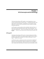
1
Configuring ST2 Services
Router Software Version 10.0
Site Manager Software Version 4.0
Software Version BNX 6.0
Site Manager Software Version BNX 6.0
Part No. 112924 Rev. A
January 1996
4401 Great America Parkway
Santa Clara, CA 95054
8 Federal Street
Billerica, MA 01821
Copyright © 1988–1996 Bay Networks, Inc.
All rights reserved. Printed in the USA. January 1996.
The information in this document is subject to change without notice. The statements, configurations, technical data, and
recommendations in this document are believed to be accurate and reliable, but are presented without express or implied
warranty. Users must take full responsibility for their applications of any products specified in this document. The
information in this document is proprietary to Bay Networks, Inc.
The software described in this document is furnished under a license agreement and may only be used in accordance with the
terms of that license. A summary of the Software License is included in this document.
Restricted Rights Legend
Use, duplication, or disclosure by the United States Government is subject to restrictions as set forth in subparagraph
(c)(1)(ii) of the Rights in Technical Data and Computer Software clause at DFARS 252.227-7013.
Notice for All Other Executive Agencies
Notwithstanding any other license agreement that may pertain to, or accompany the delivery of, this computer software, the
rights of the United States Government regarding its use, reproduction, and disclosure are as set forth in the Commercial
Computer Software-Restricted Rights clause at FAR 52.227-19.
Trademarks of Bay Networks, Inc.
ACE, AFN, BCN, BLN, BN, CN, FRE, LN, Optivity, SynOptics, SynOptics Communications, Wellfleet and the Wellfleet
logo are registered trademarks and AN, ANH, ASN, BaySIS, BayStack, BCNX, BLNX, BNX, EZ Internetwork, EZ LAN,
FN, PathMan, PhonePlus, PPX, Quick2Config, RouterMan, SPEX, Bay Networks, Bay Networks Press, the Bay Networks
logo and the SynOptics logo are trademarks of Bay Networks, Inc.
Third-Party Trademarks
All other trademarks and registered trademarks are the property of their respective owners.
Statement of Conditions
In the interest of improving internal design, operational function, and/or reliability, Bay Networks, Inc. reserves the right to
make changes to the products described in this document without notice.
Bay Networks, Inc. does not assume any liability that may occur due to the use or application of the product(s) or circuit
layout(s) described herein.
Portions of the code in this software product are Copyright © 1988, Regents of the University of California. All rights
reserved. Redistribution and use in source and binary forms of such portions are permitted, provided that the above copyright
notice and this paragraph are duplicated in all such forms and that any documentation, advertising materials, and other
materials related to such distribution and use acknowledge that such portions of the software were developed by the
University of California, Berkeley. The name of the University may not be used to endorse or promote products derived from
such portions of the software without specific prior written permission.
SUCH PORTIONS OF THE SOFTWARE ARE PROVIDED “AS IS” AND WITHOUT ANY EXPRESS OR IMPLIED
WARRANTIES, INCLUDING, WITHOUT LIMITATION, THE IMPLIED WARRANTIES OF MERCHANTABILITY
AND FITNESS FOR A PARTICULAR PURPOSE.
In addition, the program and information contained herein are licensed only pursuant to a license agreement that contains
restrictions on use and disclosure (that may incorporate by reference certain limitations and notices imposed by third parties).
Bay Networks Software License
Note: This is Bay Networks basic license document. In the absence of a
software license agreement specifying varying terms, this license — or the
license included with the particular product — shall govern licensee’s use of
Bay Networks software.
This Software License shall govern the licensing of all software provided to licensee by Bay Networks (“Software”).
Bay Networks will provide licensee with Software in machine-readable form and related documentation
(“Documentation”). The Software provided under this license is proprietary to Bay Networks and to third parties from
whom Bay Networks has acquired license rights. Bay Networks will not grant any Software license whatsoever, either
explicitly or implicitly, except by acceptance of an order for either Software or for a Bay Networks product
(“Equipment”) that is packaged with Software. Each such license is subject to the following restrictions:
1.
Upon delivery of the Software, Bay Networks grants to licensee a personal, nontransferable, nonexclusive license
to use the Software with the Equipment with which or for which it was originally acquired, including use at any
of licensee’s facilities to which the Equipment may be transferred, for the useful life of the Equipment unless
earlier terminated by default or cancellation. Use of the Software shall be limited to such Equipment and to such
facility. Software which is licensed for use on hardware not offered by Bay Networks is not subject to restricted
use on any Equipment, however, unless otherwise specified on the Documentation, each licensed copy of such
Software may only be installed on one hardware item at any time.
2.
Licensee may use the Software with backup Equipment only if the Equipment with which or for which it was
acquired is inoperative.
3.
Licensee may make a single copy of the Software (but not firmware) for safekeeping (archives) or backup
purposes.
4.
Licensee may modify Software (but not firmware), or combine it with other software, subject to the provision
that those portions of the resulting software which incorporate Software are subject to the restrictions of this
license. Licensee shall not make the resulting software available for use by any third party.
5.
Neither title nor ownership to Software passes to licensee.
6.
Licensee shall not provide, or otherwise make available, any Software, in whole or in part, in any form, to any
third party. Third parties do not include consultants, subcontractors, or agents of licensee who have licensee’s
permission to use the Software at licensee’s facility, and who have agreed in writing to use the Software only in
accordance with the restrictions of this license.
7.
Third-party owners from whom Bay Networks has acquired license rights to software that is incorporated into
Bay Networks products shall have the right to enforce the provisions of this license against licensee.
8.
Licensee shall not remove or obscure any copyright, patent, trademark, trade secret, or similar intellectual
property or restricted rights notice within or affixed to any Software and shall reproduce and affix such notice on
any backup copy of Software or copies of software resulting from modification or combination performed by
licensee as permitted by this license.
Bay Networks, Inc.
4401 Great America Parkway, Santa Clara, CA 95054
8 Federal Street, Billerica, MA 01821
Bay Networks Software License (continued)
9.
Licensee shall not reverse assemble, reverse compile, or in any way reverse engineer the Software. [Note: For
licensees in the European Community, the Software Directive dated 14 May 1991 (as may be amended from time
to time) shall apply for interoperability purposes. Licensee must notify Bay Networks in writing of any such
intended examination of the Software and Bay Networks may provide review and assistance.]
10. Notwithstanding any foregoing terms to the contrary, if licensee licenses the Bay Networks product “Site
Manager,” licensee may duplicate and install the Site Manager product as specified in the Documentation. This
right is granted solely as necessary for use of Site Manager on hardware installed with licensee’s network.
11. This license will automatically terminate upon improper handling of Software, such as by disclosure, or Bay
Networks may terminate this license by written notice to licensee if licensee fails to comply with any of the
material provisions of this license and fails to cure such failure within thirty (30) days after the receipt of written
notice from Bay Networks. Upon termination of this license, licensee shall discontinue all use of the Software
and return the Software and Documentation, including all copies, to Bay Networks.
12. Licensee’s obligations under this license shall survive expiration or termination of this license.
Bay Networks, Inc.
4401 Great America Parkway, Santa Clara, CA 95054
8 Federal Street, Billerica, MA 01821
Contents
About This Guide
Software Suites ................................................................................................................ xi
Audience ...........................................................................................................................xii
Bay Networks Customer Support .....................................................................................xii
CompuServe ..............................................................................................................xii
InfoFACTS .................................................................................................................xiii
World Wide Web ........................................................................................................xiii
How to Get Help ..............................................................................................................xiv
Conventions .....................................................................................................................xiv
Ordering Bay Networks Publications ............................................................................... xv
Acronyms ......................................................................................................................... xv
Chapter 1
ST2 Concepts and Terminology
ST2 and IP ......................................................................................................................1-1
ST2 Agents .....................................................................................................................1-2
Stream Control Messages ..............................................................................................1-3
Neighbors and Tunnels ...................................................................................................1-3
Resource Manager .........................................................................................................1-5
ST2 Features ..................................................................................................................1-5
Chapter 2
The Role of an ST2 Intermediate Agent
Setting Up a Stream Segment ........................................................................................2-1
Receiving a Connect Request from Upstream .........................................................2-2
Determining the Next Hop Downstream ...................................................................2-3
Using the IP Routing Table (IP-Inherited Routing) .............................................2-3
Using the ST2 Neighbor Table (Exploratory Routing) ........................................2-4
Establishing a Connection with a Downstream Neighbor ........................................2-4
Adding a Target to a Stream ...........................................................................................2-4
v
Forwarding ST2 Data Downstream ................................................................................2-5
Shutting Down a Stream .................................................................................................2-6
Chapter 3
Configuring an Intermediate Agent
Selecting a Slot and Configuring a Circuit ......................................................................3-2
Adding an ST2 Interface to a Circuit ...............................................................................3-2
Customizing an ST2 Interface ........................................................................................3-5
Configuring ST2 on the Router .....................................................................................3-11
Building a Neighbors Forwarding Table ........................................................................3-13
Appendix A
Site Manager Default Settings
ST2 Interface Parameter Defaults ................................................................................. A-1
ST2 Global Parameter Defaults ..................................................................................... A-2
ST2 Neighbor Parameter Defaults ................................................................................. A-2
Index
vi
Figures
Figure 1-1.
Figure 1-2.
Figure 2-1.
Figure 2-2.
Figure 3-1.
Figure 3-2.
Figure 3-3.
ST2 Point-to-Multipoint Stream ................................................................1-2
ST2 Neighbors .........................................................................................1-4
Setting Up a Point-to-Point Stream ..........................................................2-2
Adding a Target to a Stream ....................................................................2-5
IP Configuration Window ..........................................................................3-3
Edit ST2 Interfaces Window .....................................................................3-6
ST2 Base Group Parameters Window ...................................................3-11
Figure 3-4.
Figure 3-5.
ST2 Neighbors Window .........................................................................3-14
ST2 Neighbor Configuration Window .....................................................3-14
vii
Tables
Table 1-1.
ST2 Features ...........................................................................................1-5
ix
About This Guide
This guide describes how to configure a Bay Networks router or BNX platform as
a Stream Protocol 2 (ST2) intermediate agent.
Software Suites
Routing and Switching software is available in the following suites:
•
The System Suite includes IP routing, 802.1 Transparent Bridge, Source Route
Bridge, Translation Bridge, SNMP Agent, Bay Networks HDLC, PPP, OSPF,
EGP, BGP, and basic DLSw.
•
The LAN Suite includes DECnet Phase 4, AppleTalk Phase 2, OSI, VINES,
IPX, and ATM DXI, in addition to the System Suite.
•
The WAN Suite includes ATM DXI, Frame Relay, LAPB, and X.25, in
addition to the System Suite.
•
The Corporate Suite includes the System, LAN, and WAN suites in their
entirety.
•
The ARE ATM Suite provides RFC 1483 and 1577 compliance, ATM UNI 3.0
signaling, in addition to the LAN Suite.
•
The ARE VNR Corporate Suite provides ATM Forum LAN Emulation, in
addition to the ARE ATM Suite and Corporate Suite.
•
The BNX Suite includes IP Routing, SNMP Agent, Bay Networks HDLC,
PPP, OSPF, EGP, BGP, File-Based Performance Statistics, Frame Relay
switching, and Frame Relay billing, and selected components from the
Corporate, ARE ATM, and ARE VNR Corporate suites.
Availability of features and functionality described in this guide depends on the
suites you are using.
xi
Configuring ST2 Services
Audience
This manual is intended for network administrators who have experience using
Site Manager to configure the Internet Protocol (IP) and IP routing protocols on
Bay Networks routers.
Bay Networks Customer Support
Bay Networks provides live telephone technical support to our distributors,
resellers, and service-contracted customers from two U.S. and three international
support centers. If you have purchased your Bay Networks product from a
distributor or authorized reseller, contact the technical support staff of that
distributor or reseller for assistance with installation, configuration,
troubleshooting, or integration issues.
Customers also have the option of purchasing direct support from Bay Networks
through a variety of service programs. The programs include priority access
telephone support, on-site engineering assistance, software subscription, hardware
replacement, and other programs designed to protect your investment.
To purchase any of these support programs, including PhonePlus™ for 24-hour
telephone technical support, call 1-800-2LANWAN. Outside the U.S. and
Canada, call (408) 764-1000. You can also receive information on support
programs from your local Bay Networks field sales office, or purchase Bay
Networks support directly from your reseller. Bay Networks provides several
methods of receiving support and information on a nonpriority basis through the
following automated systems.
CompuServe
Bay Networks maintains an active forum on CompuServe. All you need to join us
online is a computer, a modem, and a CompuServe account. We also recommend
using the CompuServe Information Manager software, available from
CompuServe.
The Bay Networks forum contains libraries of technical and product documents
designed to help you manage and troubleshoot your Bay Networks products.
Software agents and patches are available, and the message boards are monitored
by technical staff and can be a source for problem solving and shared experiences.
xii
Customers and resellers holding Bay Networks service contracts can visit the
special libraries to acquire advanced levels of support documentation and
software.
To open an account and receive a local dial-up number, call CompuServe at
1-800-524-3388 and ask for Representative No. 591.
•
In the United Kingdom, call Freephone 0800-289378.
•
In Germany, call 0130-37-32.
•
In Europe (except for the United Kingdom and Germany), call
(44) 272-760681.
•
Outside the U.S., Canada, and Europe, call (614) 529-1349 and ask for
Representative No. 591, or consult your listings for an office near you.
Once you are online, you can reach our forum by typing the command GO
BAYNETWORKS at any ! prompt.
InfoFACTS
InfoFACTS is the Bay Networks free 24-hour fax-on-demand service. This
automated system contains libraries of technical and product documents designed
to help you manage and troubleshoot your Bay Networks products. The system
can return a fax copy to the caller or to a third party within minutes of being
accessed.
World Wide Web
The World Wide Web (WWW) is a global information system for file distribution
and online document viewing via the Internet. You need a direct connection to the
Internet and a Web Browser (such as Mosaic or Netscape).
Bay Networks maintains a WWW Home Page that you can access at http://
www.baynetworks.com. One of the menu items on the Home Page is the
Customer Support Web Server, which offers technical documents, software
agents, and an E-mail capability for communicating with our technical support
engineers.
xiii
Configuring ST2 Services
How to Get Help
For additional information or advice, contact the Bay Networks Technical
Response Center in your area:
United States
Valbonne, France
Sydney, Australia
Tokyo, Japan
1-800-2LAN-WAN
(33) 92-966-968
(61) 2-903-5800
(81) 3-328-005
Conventions
This section describes the conventions used in this guide.
angle brackets (< >)
Indicate that you choose the text to enter based on the
description inside the brackets. Do not type the
brackets when entering the command. Example: if
command syntax is ping <ip_address>, you enter ping
192.32.10.12
arrow character (➔)
Separates menu and option names in instructions.
Example: Protocols➔AppleTalk identifies the
AppleTalk option in the Protocols menu.
bold text
Indicates text that you need to enter and command
names in text. Example: Use the dinfo command.
brackets ([ ])
Indicate optional elements. You can choose none, one,
or all of the options.
italic text
Indicates variable values in command syntax
descriptions, new terms, file and directory names, and
book titles.
quotation marks (“ ”)
Indicate the title of a chapter or section within a book.
screen text
Indicates data that appears on the screen. Example: Set
Bay Networks Trap Monitor Filters
ellipsis points
vertical line (|)
xiv
.
Horizontal (. . .) and vertical ( .. ) ellipsis points indicate
omitted information.
Indicates that you enter only one of the parts of the
command. The vertical line separates choices. Do not
type the vertical line when entering the command.
Example: If the command syntax is
show at routes | nets, you enter either
show at routes or show at nets, but not both.
Ordering Bay Networks Publications
To purchase additional copies of this document or other Bay Networks
publications, order by part number from Bay Networks Press™ at the following
numbers. You may also request a free catalog of Bay Networks Press product
publications.
Phone:
FAX - U.S./Canada:
FAX - International:
1-800-845-9523
1-800-582-8000
1-916-939-1010
ANSI
American National Standards Institute
ARP
Address Resolution Protocol
ATM
Asynchronous Transfer Mode
CMIP
Common Management Information Protocol
EGP
Exterior Gateway Protocol
FDDI
Fiber Distributed Data Interface
HID
hop identifier
MAC
media access control
MOP
Maintenance Operations Protocol
OSI
Open Systems Interconnection
OSPF
Open Shortest Path First
QENET
Quad Ethernet Link Module
RIP
Routing Information Protocol
SCMP
Stream Control Message Protocol
SNMP
Simple Network Management Protocol
ST2
Stream Protocol 2
Acronyms
xv
Chapter 1
ST2 Concepts and Terminology
The Internet Stream Protocol (ST2) enables a network application to reserve
resources on internet routers for an ST2 stream — a transmission path from a data
origin to one or more data targets. The capability to reserve Internet resources
makes ST2 well suited for video conferencing, real-time simulation, and other
multimedia applications.
An ST2 stream is a point-to-point or point-to-multipoint connection. Figure 1-1
shows an ST2 stream established between a single video streaming unit — the
origin of the transmissions — and six receiving target video systems. The stream
is simplex — data flows in one direction only, downstream from the origin to the
targets.
ST2 and IP
Underlying and supporting an ST2 stream is an internet topology that includes
multiple IP routers capable of providing and guaranteeing the resources required
for the data transmission. For example, the topology underlying the stream in
Figure 1-1 includes seven routers.
An ST2 stream creates a semblance of an end-to-end connection establishment
typical of a virtual circuit protocol. However, messages are never exchanged
directly between origin and targets. Each router discovers the next-hop IP routers
and is concerned only with the part of the stream between itself and these routers.
1-1
Configuring ST2 Services
Figure 1-1. ST2 Point-to-Multipoint Stream
ST2 Agents
Each IP router supporting the stream is configured with the hardware and software
required for ST2 data transmissions; in addition, each router is running ST2 agent
software. Such routers are considered to be ST2 capable.
1-2
ST2 Concepts and Terminology
An ST2 agent that receives control messages and stream data directly from an
origin application or delivers control messages and stream data to a target
application is considered to be a host agent. ST2 agents that forward control
messages and data to the next agent downstream are considered to be intermediate
agents. A Bay Networks router can be configured as an intermediate ST2 agent.
The ST2 environment in Figure 1-1 includes three Bay Networks routers (BayNet/
ST2 1, BayNet/ST2 2, and BayNet/ST2 3).
Stream Control Messages
ST2 agents communicate with each other by exchanging messages defined by the
Stream Control Message Protocol (SCMP).
For example, an origin that wants to establish a stream sends an SCMP connect
message to the next-hop IP router downstream. The connection request includes
•
A list of one or more targets.
•
A hop identifier (HID). An HID is suggested by the upstream agent. The
downstream agent may accept the HID or propose an alternative HID.
•
A flowspec listing the network resources required for the stream.
To accept a connection request from an upstream agent, the agent returns an
SCMP ACCEPT message.
In “ST2 Features” on page 1-5, Table 1-1 lists all the SCMP messages currently
supported by the Bay Networks implementation of ST2.
Neighbors and Tunnels
An ST2 agent exchanges SCMP messages with next-hop agents. In an ST2
environment, next-hop agents are considered to be neighbors.
Neighbors can be connected in two ways — directly or through an ST2 tunnel. In
Figure 1-2 the ST2 agent on Router A has two neighbors, the agent on Router B
and the agent on Router D. Router A and Router B are connected directly — they
both have an interface to Network 1. Router A and Router D are connected
through a tunnel that includes Network 2 and Network 3 and a router that does not
have ST2 capabilities, Router C.
1-3
Configuring ST2 Services
Tunnels are configured by the network administrator to establish ST2 streams in
networks where not all IP routers are ST2 capable. For transmission through a
tunnel, SCMP messages and ST2 data are encapsulated in IP datagrams and
forwarded through a non-ST2 router, and decapsulated at the destination.
A non-ST2 router can provide a tunnel for both stream data and control messages;
however, a router that lacks ST2 capability cannot guarantee the resources listed
in the flowspec.
Figure 1-2. ST2 Neighbors
1-4
ST2 Concepts and Terminology
Resource Manager
An SCMP CONNECT request includes a flowspec that lists the communications
resources required by the proposed stream.
On a Bay Networks router, an ST2 agent that receives a connect request from an
agent upstream passes the flowspec to the local Resource Manager.
The Resource Manager allocates and guarantees the resources required by the
stream.
For information on the Resource Manager, see Configuring Line Services or
Configuring Customer Access and Trunks (BNX Software), depending on the type
of installed software.
ST2 Features
Table 1-1 lists ST2 features and indicates the ones called out in RFC 1190,
“Experimental Internet Stream Protocol, Version 2,” and the ones supported by the
current version of Bay Networks router software.
Table 1-1. ST2 Features
Feature
RFC 1190
Current Version
Multiline circuits
n/a
yes
Peak bandwidth reservation
n/a
yes
Bandwidth policing
n/a
yes
Autorouting using IP route tables
n/a
yes
IP encapsulation of ST2
yes
yes
Adding targets during connection
yes
yes
HID negotiation
yes
yes
SCMP(ACCEPT)
yes
yes
SCMP(ACK)
yes
yes
SCMP(CHANGE REQUEST)
yes
no
SCMP(CHANGE)
yes
no
(continued)
1-5
Configuring ST2 Services
Table 1-1. ST2 Features (continued)
1-6
Feature
RFC 1190
Current Version
SCMP(CONNECT)
yes
yes
SCMP(DISCONNECT)
yes
yes
SCMP(ERROR IN REQUEST)
yes
yes
SCMP(ERROR IN RESPONSE)
yes
yes
SCMP(HELLO)
yes
yes
SCMP(HID-CHANGE)
yes
yes
SCMP(HID-APPROVE)
yes
yes
SCMP(HID-REJECT)
yes
yes
SCMP(HID-CHANGE-REQUEST)
yes
no
SCMP(NOTIFY)
yes
no
SCMP(REFUSE)
yes
yes
SCMP(STATUS)
yes
no
SCMP(STATUS-RESPONSE)
yes
no
SCMP (OPCODE 18:userdata)
no
yes
Chapter 2
The Role of an ST2 Intermediate Agent
This chapter examines the role played by an intermediate ST2 agent running on a
Bay Networks router in an ST2 environment. The chapter consists of the
following sections:
•
“Setting Up a Stream Segment” on page 2-1
•
“Adding a Target to a Stream” on page 2-4
•
“Forwarding ST2 Data Downstream” on page 2-5
•
“Shutting Down a Stream” on page 2-6
Setting Up a Stream Segment
As part of ST2 stream setup, a Bay Networks router configured as an intermediate
agent:
1. Receives an SCMP connect request from an upstream ST2 neighbor
2. Establishes a connection with the upstream neighbor
3. Determines the appropriate downstream neighbor
4. Reserves resources on the downstream interface
5. Sends an SCMP connection request to the downstream neighbor
6. Establishes a connection with the downstream neighbor
Stream setup creates a semblance of an end-to-end connection establishment
typical of a virtual circuit protocol. However, control messages are never
exchanged directly between origin and targets.
2-1
Configuring ST2 Services
Receiving a Connect Request from Upstream
An intermediate ST agent receives connect requests on ST2 interfaces from
upstream agents. A connect request can specify a single target (the typical case) or
multiple targets. In Figure 2-1, for example, BayNet/ST2 1, an intermediate agent,
receives a connect request from ST2 1. The connect request specifies a single
target for the stream, T6. The request also includes a flowspec listing the network
resources required for the transmission.
Figure 2-1. Setting Up a Point-to-Point Stream
2-2
The Role of an ST2 Intermediate Agent
The ST2 agent on BayNet/ST2 1, using the information in the connection request:
1. Negotiates a hop identifier (HID) with the previous hop, ST2 1
2. Reserves the local and network resources required to support the stream
3. Passes the flowspec to the Bay Networks resource manager
Determining the Next Hop Downstream
An ST2 agent on a Bay Networks router uses two methods to determine the next
downstream hop in the stream:
•
IP-inherited routing (the primary method), using the IP routing table
•
ST2 exploratory routing (the backup method), using the ST2 neighbor table
Using the IP Routing Table (IP-Inherited Routing)
In IP-inherited routing, the ST2 agent obtains the address of the next-hop router
from the IP routing table. This table consists of entries describing routes that have
been learned by the routing protocols configured on the router (OSPF and BGP,
for example). The routing table also contains entries for static routes — that is,
routes that have been inserted by the network administrator.
Each entry in the IP routing table includes a target IP network, a next-hop IP
address, an interface address, and other information. There is no information in a
routing table entry, however, to distinguish an ST2 route (that is, a hop with an
ST2-capable router on the other end). For this reason, it is possible for ST2 to
select a route that it cannot use.
If ST2 selects a route that is not ST2 capable (and does not provide a tunnel to an
ST2 agent), ST2 does not use the route and returns an SCMP REFUSE message
upstream with the reason code No Route to Destination.
If the required resources are not available via a path stored in the IP routing table,
ST2 uses exploratory routing. See “Using the ST2 Neighbor Table (Exploratory
Routing)” on page 2-4.
2-3
Configuring ST2 Services
Using the ST2 Neighbor Table (Exploratory Routing)
In exploratory routing, the ST2 agent obtains information about its ST2-capable
neighbors from its ST2 neighbors table. This table, which is configured by the
network administrator, consists of entries that describe the characteristics of a
next-hop neighbor and provide the next-hop address.
The table notes those neighbors that can perform exploratory routing. When
resources are not available via a route stored in the IP routing table, the ST2 agent
selects a neighbor that is capable of exploratory routing.
Establishing a Connection with a Downstream Neighbor
Once the SCMP session has been established, the downstream intermediate agent
becomes the upstream agent for the next hop and issues a connect message. The
message contains an HID value and the flowspec for the stream.
Adding a Target to a Stream
Once a stream has been established from the origin to a target, the origin can issue
additional connect requests to add targets to the stream. Each connect request
identifies the stream and specifies the target to add. In Figure 2-2, for example,
target T4 has been added to the stream established between the video origin and
T6.
To create a new branch in the stream (if one is required), the intermediate ST2
agent follows the steps described in “Determining the Next Hop Downstream” on
page 2-3 and in the previous section, “Establishing a Connection with a
Downstream Neighbor.”
2-4
The Role of an ST2 Intermediate Agent
Figure 2-2. Adding a Target to a Stream
Forwarding ST2 Data Downstream
An ST agent receives data packets encapsulated by an ST header. A data packet
received by an ST agent contains the HID assigned to the stream for the branch
from the previous hop to itself. The agent uses the HID to obtain quickly the
necessary forwarding information for the next hop.
2-5
Configuring ST2 Services
The forwarding information identifies the next-hop agent and includes the HID
and address of the next hop.
Shutting Down a Stream
Two SCMP messages — Disconnect and Refuse — allow ST2 agents to shut
down a stream in an orderly manner.
An intermediate agent receives SCMP Disconnect messages on its upstream ST2
interfaces. Disconnect messages can be generated by the origin or, in the case of
network failure, by a next-hop agent upstream.
An intermediate agent receives SCMP Refuse messages on its downstream ST2
interfaces. Refuse messages can be generated by an ST2 target or by a next-hop
agent downstream.
The ST2 agent acknowledges the request to shut down the stream and performs
the appropriate action. In the case of a Disconnect message, the agent sends a
Disconnect to the next-hop agent or agents downstream. In the case of a Refuse
message, the agent sends a Refuse message to the next hop upstream.
2-6
Chapter 3
Configuring an Intermediate Agent
For each ST2 parameter, this manual provides default settings, valid parameter
options, the parameter function, instructions for setting the parameter, and the
Management Information Base (MIB) object ID.
This chapter shows you how to set parameters using Site Manager. You can also
use the Technician Interface to modify parameters (by issuing set and commit
commands that specify the MIB object ID). For more information about using the
Technician Interface to access the MIB, refer to Using Technician Interface
Software.
Caution: The Technician Interface does not verify that the value you enter for
a parameter is valid. Entering an invalid value can corrupt your
configuration.
The following sections show you how to use Site Manager to configure a Bay
Networks router as an ST2-capable intermediate agent:
•
“Selecting a Slot and Configuring a Circuit” on page 3-2
•
“Adding an ST2 Interface to a Circuit” on page 3-2
•
“Customizing an ST2 Interface” on page 3-5
•
“Configuring ST2 on the Router” on page 3-11
•
“Building a Neighbors Forwarding Table” on page 3-13
3-1
Configuring ST2 Services
Selecting a Slot and Configuring a Circuit
Before you can add an ST2 interface to a circuit, you must perform the following
operations to ensure that the slot is properly set up for IP and ST2:
1. Open a configuration file.
2. Specify a slot and configure a link module on the slot (if the configuration file
is a local-mode file).
3. Select a link or net module connector and configure a circuit on the connector,
or configure a WAN circuit if this connector requires one.
For instructions on performing these operations, refer to Configuring Routers or
Configuring Customer Access and Trunks (BNX Software), depending on the type
of installed software.
Adding an ST2 Interface to a Circuit
ST2 requires the services of IP. Every circuit that you configure with an ST2
interface must also be configured with an IP interface.
Once you have set up a slot and configured a circuit, you are finished with the Add
Circuit window.
1.
Click on OK on the Add Circuit window.
The Select Protocols window appears.
2.
Select IP and ST2 from the Select Protocols window and click on OK.
Site Manager displays the IP configuration window (Figure 3-1).
3-2
3.
Edit the parameters on the screen.
4.
Click on OK.
Configuring an Intermediate Agent
Figure 3-1. IP Configuration Window
Parameter:
IP Address
Default:
None
Options:
0.0.0.0 or any valid IP address
Function:
Instructions:
MIB Object ID:
Assigns a 32-bit IP address to the interface.
Enter the IP address of the interface in dotted decimal notation. Enter
0.0.0.0 to configure an unnumbered interface on the circuit.
1.3.6.1.4.1.18.3.5.3.2.1.4.1.4
3-3
Configuring ST2 Services
Parameter:
Subnet Mask
Default:
None
Options:
The Configuration Manager automatically calculates an appropriate
subnet mask, depending on the class of the network to which the interface
connects. However, you can change the subnet mask with this parameter.
Function:
Instructions:
MIB Object ID:
Parameter:
Specifies the network and subnetwork portion of the 32-bit IP address.
Either accept the assigned subnet mask, or enter another subnet mask in
dotted decimal notation.
1.3.6.1.4.1.18.3.5.3.2.1.4.1.6
Transmit Bcast Addr
Default:
0.0.0.0
Options:
0.0.0.0 or any valid IP broadcast address
Function:
Specifies the broadcast address that this IP subnet uses to broadcast
packets.
Accepting 0.0.0.0 for this parameter specifies that the IP router will use a
broadcast address with a host portion of all 1s. Accepting 0.0.0.0 does not
configure the router to use the address 0.0.0.0 to broadcast packets. For
example, if you have IP address 123.1.1.1 and a subnet mask of
255.255.255.0, accepting the default value 0.0.0.0 configures the IP router
to use the address 123.1.1.255 to broadcast packets.
To set the explicit broadcast address of all 1s, enter 255.255.255.255 for
this parameter.
Instructions:
Accept the default, 0.0.0.0, unless the calculated broadcast address (host
portion) of all 1s is not adequate. If this is the case, then enter the
appropriate IP broadcast address in dotted decimal notation.
If you set the IP Address parameter to 0.0.0.0 (to configure an
unnumbered interface), Site Manager automatically sets this parameter to
255.255.255.255.
MIB Object ID:
3-4
1.3.6.1.4.1.18.3.5.3.2.1.4.1.8
Configuring an Intermediate Agent
Parameter:
UnNumbered Assoc Address
Note: ST2 cannot be configured on an unnumbered interface in the current
software version.
Default:
Range:
Function:
None
Any valid IP address
Specifies an address that IP uses when sourcing a packet.
RIP uses this address to make decisions about advertising subnets over
the unnumbered interface. RIP advertises subnets over the unnumbered
interface if the subnets have the same mask as the associated address.
Instructions:
MIB Object ID:
Specify the address of any numbered interface on the router.
1.3.6.1.4.1.18.3.5.3.2.1.4.1.110
Customizing an ST2 Interface
This section shows you how to customize an interface that you have added to a
router circuit. Begin at the Configuration Manager window and perform the
following operations:
1.
Select Protocols➔IP➔ST2➔Interfaces.
The Edit ST2 Interfaces window appears (Figure 3-2).
2.
Edit the parameters and click on Apply.
3.
Click on Done.
3-5
Configuring ST2 Services
Figure 3-2. Edit ST2 Interfaces Window
Parameter:
Enable
Default:
Enable
Options:
Enable | Disable
Function:
Instructions:
MIB Object ID:
3-6
Enables and disables ST2 on this interface.
By default, the router enables ST2 when you add the ST2 protocol to the
circuit. If you want to disable ST2 on the interface, use this parameter.
1.3.6.1.4.1.18.3.5.16.1.2.2.1.2
Configuring an Intermediate Agent
Parameter:
Default:
Range:
Function:
Instructions:
MIB Object ID:
Parameter:
Default:
Range:
Function:
Instructions:
MIB Object ID:
Parameter:
IP Address
None
Any valid IP address
Specifies the IP address of this ST2 interface.
Supply a unique IP address in dotted decimal notation.
1.3.6.1.4.1.18.3.5.16.1.2.2.1.6
Accept Time Out
10 seconds
1 to 999
Specifies the time in seconds between ST2 accept message retries on this
interface.
Use the default unless the application requires otherwise.
1.3.6.1.4.1.18.3.5.16.1.2.2.1.7
Accept Retry
Default:
3 retries
Range:
1 to 100
Function:
Instructions:
MIB Object ID:
Specifies the maximum retry count for accept messages on this interface.
Use the default unless the application requires otherwise.
1.3.6.1.4.1.18.3.5.16.1.2.2.1.8
3-7
Configuring ST2 Services
Parameter:
Default:
Range:
Function:
Instructions:
MIB Object ID:
Parameter:
10 seconds
1 to 999
Specifies the time in seconds between ST2 connect message retries on
this interface.
Use the default unless the application requires otherwise.
1.3.6.1.4.1.18.3.5.16.1.2.2.1.9
Connect Retry
Default:
5 retries
Range:
1 to 100
Function:
Instructions:
MIB Object ID:
Parameter:
Default:
Range:
Function:
Instructions:
MIB Object ID:
3-8
Connect Time Out
Specifies the maximum retry count for connect messages on this
interface.
Use the default unless the application requires otherwise.
1.3.6.1.4.1.18.3.5.16.1.2.2.1.10
Disconnect Time Out
10 seconds
1 to 999
Specifies the time in seconds between ST2 disconnect message retries on
this interface.
Use the default unless the application requires otherwise.
1.3.6.1.4.1.18.3.5.16.1.2.2.1.11
Configuring an Intermediate Agent
Parameter:
Disconnect Retry
Default:
3 retries
Options:
1 to 100
Function:
Instructions:
MIB Object ID:
Parameter:
Default:
Range:
Function:
Instructions:
MIB Object ID:
Parameter:
Specifies the maximum retry count for disconnect messages on this
interface.
Use the default unless the application requires otherwise.
1.3.6.1.4.1.18.3.5.16.1.2.2.1.12
HID Change Time Out
10 seconds
1 to 999
Specifies the time in seconds between ST2 HID change message retries
on this interface.
Use the default unless the application requires otherwise.
1.3.6.1.4.1.18.3.5.16.1.2.2.1.13
HID Change Retry
Default:
3 retries
Range:
1 to 100
Function:
Instructions:
MIB Object ID:
Specifies the maximum retry count for HID change messages on this
interface.
Use the default unless the application requires otherwise.
1.3.6.1.4.1.18.3.5.16.1.2.2.1.14
3-9
Configuring ST2 Services
Parameter:
Default:
Range:
Function:
Instructions:
MIB Object ID:
Parameter:
10 seconds
1 to 999
Specifies the time in seconds between ST2 refuse message retries on this
interface.
Use the default unless the application requires otherwise.
1.3.6.1.4.1.18.3.5.16.1.2.2.1.15
Refuse Retry
Default:
3 retries
Range:
1 to 100
Function:
Instructions:
MIB Object ID:
Parameter:
Default:
Range:
Function:
Instructions:
MIB Object ID:
3-10
Refuse Time Out
Specifies the maximum retry count for refuse messages on this interface.
Use the default unless the application requires otherwise.
1.3.6.1.4.1.18.3.5.16.1.2.2.1.16
Hello Time Out
10 seconds
1 to 100
Specifies the time in seconds between ST2 hello message retries on this
interface.
Use the default unless the application requires otherwise.
1.3.6.1.4.1.18.3.5.16.1.2.2.1.17
Configuring an Intermediate Agent
Parameter:
Hello Retry
Default:
5 retries
Range:
1 to 100
Function:
Instructions:
MIB Object ID:
Specifies the maximum retry count for hello messages on this interface.
Use the default unless the application requires otherwise.
1.3.6.1.4.1.18.3.5.16.1.2.2.1.18
Configuring ST2 on the Router
An ST2 agent runs on every slot that has been configured with an ST2 interface.
To customize the way an ST2 agent operates on the router, begin at the
Configuration Manager window and perform the following operations:
1.
Select Protocols➔IP➔ST2➔Global.
The ST2 Base Group Parameters window appears (Figure 3-3).
2.
Edit the parameters and click on OK.
Figure 3-3. ST2 Base Group Parameters Window
3-11
Configuring ST2 Services
Parameter:
Enable
Default:
Enable
Options:
Enable | Disable
Function:
Instructions:
MIB Object ID:
Parameter:
By default, the router starts ST2 on the slot when you configure an ST2
interface on a circuit. If you do not want ST2 to be started on the slot,
select Disable.
1.3.6.1.4.1.18.3.5.16.1.2.1.2
Tunnelling Capability
Default:
No
Options:
Yes | No
Function:
Instructions:
MIB Object ID:
Parameter:
Specifies whether ST2 can use a tunnel to establish a neighbor-toneighbor connection.
By default, ST2 does not have tunneling capability. If your network
requires the use of tunnels, select Yes.
1.3.6.1.4.1.18.3.5.16.1.2.1.5
Tunnelling Enable
Default:
Disable
Options:
Enable | Disable
Function:
Instructions:
MIB Object ID:
3-12
Determines whether ST2 is enabled on the slot.
Enables and disables tunneling on a router that has tunneling capability.
If you select Yes for the Tunneling Capability parameter, use this
parameter to enable and disable that feature on the router.
1.3.6.1.4.1.18.3.5.16.1.2.1.6
Configuring an Intermediate Agent
Building a Neighbors Forwarding Table
The network administrator constructs an ST2 neighbors forwarding table on the
router and supplies an entry for each neighbor router that has ST2 capability.
To create an entry describing an ST2 neighbor, begin at the Configuration
Manager window and perform the following operations:
1.
Select Protocols➔IP➔ST2➔Neighbors.
The ST2 Neighbors window appears (Figure 3-4).
2.
Click on Add.
The Neighbor Configuration window appears (Figure 3-5).
3.
Edit the parameters in this window to supply the IP address of the
neighbor and indicate the type of neighbor.
4.
Click on OK.
The ST2 Neighbors window reappears, displaying the addresses of all
configured neighbors.
5.
Click on the neighbor whose characteristics you want to describe or
modify.
6.
Edit the parameters in this window and click on Apply.
The router uses the information you have supplied to create a forwarding table
entry for the neighbor.
7.
Click on Done.
3-13
Configuring ST2 Services
Figure 3-4. ST2 Neighbors Window
Figure 3-5. ST2 Neighbor Configuration Window
3-14
Configuring an Intermediate Agent
Parameter:
Enable
Default:
Enable
Options:
Enable | Disable
Function:
Instructions:
MIB Object ID:
Parameter:
Specifies whether the record for this neighbor is active.
Use this parameter to disable a configured neighbor.
1.3.6.1.4.1.18.3.5.16.1.2.3.1.2
Route Exploration Capability
Default:
No
Options:
Yes | No
Function:
Instructions:
MIB Object ID:
Parameter:
Specifies whether the neighbor is capable of route exploration.
Determine this characteristic of the ST2 neighbor and supply the proper
value.
1.3.6.1.4.1.18.3.5.16.1.2.3.1.2.4
Hello Protocol
Default:
Enable
Options:
Enable | Hello When Stream Active | Disable
Function:
Specifies whether the router should send Hello messages to the neighbor.
The parameter also specifies the type of Hello procedure.
Instructions:
Select Enable to use the normal Bay Networks hello procedure. Select
Hello When Stream Active to use the hello procedure only when a stream
is running to a neighbor.
MIB Object ID:
1.3.6.1.4.1.18.3.5.16.1.2.3.1.2.5
3-15
Configuring an Intermediate Agent
Parameter:
Neighbor Type
Default:
Local
Options:
Local | Tunnel
Function:
Instructions:
MIB Object ID:
Parameter:
Default:
Range:
Function:
Instructions:
MIB Object ID:
Parameter:
Default:
Range:
Function:
Instructions:
MIB Object ID:
Specifies the type of connection to this neighbor.
Set this parameter to Tunnel if the router is connected to the neighbor via
an ST2 tunnel.
1.3.6.1.4.1.18.3.5.16.1.2.3.1.2.6
Neighbor Priority Level
8
1 to 16
Assigns a priority value to the neighbor.
If you enter multiple ST2 route exploration neighbors in the forwarding
table, use this parameter to rank them. First choice is the neighbor with
the lowest value.
1.3.6.1.4.1.18.3.5.16.1.2.3.1.2.7
Next Hop IP Address
None
A valid IP address
Specifies the IP address of the next-hop router or host.
Set to the IP address of the neighbor (router or host).
1.3.6.1.4.1.18.3.5.16.1.2.3.1.2.3
3-16
Appendix A
Site Manager Default Settings
This appendix lists the default ST2 settings for Site Manager. Use the
Configuration Manager to edit any of the Site Manager default settings listed here.
ST2 Interface Parameter Defaults
Parameter
Default
Enable
Enable
IP Address
None
Accept Time Out
10 seconds
Accept Retry
3 retries
Connect Time Out
10 seconds
Connect Retry
5 retries
Disconnect Time Out
10 seconds
Disconnect Retry
3 retries
HID Change Time Out
10 seconds
HID Change Retry
3 retries
Refuse Time Out
10 seconds
Refuse Retry
3 retries
Hello Time Out
10 seconds
Hello Retry
5 retries
A-1
Configuring ST2 Services
ST2 Global Parameter Defaults
Parameter
Default
Enable
Enable
Tunneling Capability
No
Tunneling Enable
Disable
ST2 Neighbor Parameter Defaults
A-2
Parameter
Default
Route Exploration Capability
No
Hello Protocol
Enable
Neighbor Type
Local
Neighbor Priority Level
8
Next Hop IP Address
None
Index
A
agent, defined, 1-2
B
Bay Networks publications, ordering, x
C
I
intermediate agent, defined, 1-3
internet, relationship to ST2, 1-1
IP parameters
IP Address, 3-3
Subnet Mask, 3-4
Transmit Bcast Addr, 3-4
IP-inherited routing, 2-3
connect request
forwarding downstream, 2-4
receiving from upstream, 2-2
N
D
neighbor, defined, 1-3
next hop, determining, 2-3
data packets, forwarding downstream, 2-5
E
exploratory routing, 2-4
F
flowspec, 1-3
H
hop identifier (HID), 1-3
host agent, defined, 1-3
O
origin, definition of, 1-1
R
resource manager, role in ST2 setup, 1-5
routing
exploratory, 2-4
IP-inherited, 2-3
S
SCMP (Stream Control Message Protocol), 1-3
Index-1
ST2 parameters
global
Enable, 3-12
Tunnelling Capability, 3-12
Tunnelling Enable, 3-12
interface
Accept Retry, 3-7
Accept Time Out, 3-7
Connect Retry, 3-8
Connect Time Out, 3-8
Disconnect Retry, 3-9
Disconnect Time Out, 3-8
Enable, 3-6
Hello Retry, 3-11
Hello Time Out, 3-10
HID Change Retry, 3-9
HID Change Time Out, 3-9
IP Address, 3-7, 1
Refuse Retry, 3-10
Refuse Time Out, 3-10
neighbors
Enable, 3-15
Hello Protocol, 3-15
Neighbor Priority Level, 3-16
Neighbor Type, 3-16
Next Hop IP Address, 3-16
Route Exploration Capability, 3-15
ST2-capable, defined, 1-2
stream
definition of, 1-1
setting up, 2-1
shutting down, 2-6
Stream Control Message Protocol (SCMP), 1-3
T
target
adding to a stream, 2-4
definition of, 1-1
tunnel, defined, 1-4
Index-2