1
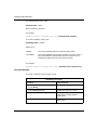
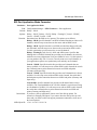
BayRS Version 14.00
Part No. 308621-14.00 Rev 00
September 1999
4401 Great America Parkway
Santa Clara, CA 95054
Configuring Dial Services
Copyright © 1999 Nortel Networks
All rights reserved. Printed in the USA. September 1999.
The information in this document is subject to change without notice. The statements, configurations, technical data,
and recommendations in this document are believed to be accurate and reliable, but are presented without express or
implied warranty. Users must take full responsibility for their applications of any products specified in this document.
The information in this document is proprietary to Nortel Networks NA Inc.
The software described in this document is furnished under a license agreement and may only be used in accordance
with the terms of that license. A summary of the Software License is included in this document.
Trademarks
NORTEL NETWORKS is a trademark of Nortel Networks.
Bay Networks, ACE, AFN, AN, BCN, BLN, BN, CN, FRE, LN, Optivity, and PPX are registered trademarks and
Advanced Remote Node, ANH, ARN, ASN, BayRS, BaySecure, BayStack, BCC, Centillion, Passport, SPEX, and
System 5000 are trademarks of Nortel Networks.
Microsoft, MS, MS-DOS, Win32, Windows, and Windows NT are registered trademarks of Microsoft Corporation.
All other trademarks and registered trademarks are the property of their respective owners.
Restricted Rights Legend
Use, duplication, or disclosure by the United States Government is subject to restrictions as set forth in subparagraph
(c)(1)(ii) of the Rights in Technical Data and Computer Software clause at DFARS 252.227-7013.
Notwithstanding any other license agreement that may pertain to, or accompany the delivery of, this computer
software, the rights of the United States Government regarding its use, reproduction, and disclosure are as set forth in
the Commercial Computer Software-Restricted Rights clause at FAR 52.227-19.
Statement of Conditions
In the interest of improving internal design, operational function, and/or reliability, Nortel Networks NA Inc. reserves
the right to make changes to the products described in this document without notice.
Nortel Networks NA Inc. does not assume any liability that may occur due to the use or application of the product(s)
or circuit layout(s) described herein.
Portions of the code in this software product may be Copyright © 1988, Regents of the University of California. All
rights reserved. Redistribution and use in source and binary forms of such portions are permitted, provided that the
above copyright notice and this paragraph are duplicated in all such forms and that any documentation, advertising
materials, and other materials related to such distribution and use acknowledge that such portions of the software were
developed by the University of California, Berkeley. The name of the University may not be used to endorse or
promote products derived from such portions of the software without specific prior written permission.
SUCH PORTIONS OF THE SOFTWARE ARE PROVIDED “AS IS” AND WITHOUT ANY EXPRESS OR
IMPLIED WARRANTIES, INCLUDING, WITHOUT LIMITATION, THE IMPLIED WARRANTIES OF
MERCHANTABILITY AND FITNESS FOR A PARTICULAR PURPOSE.
In addition, the program and information contained herein are licensed only pursuant to a license agreement that
contains restrictions on use and disclosure (that may incorporate by reference certain limitations and notices imposed
by third parties).
ii
308621-14.00 Rev 00
Nortel Networks NA Inc. Software License Agreement
NOTICE: Please carefully read this license agreement before copying or using the accompanying software or
installing the hardware unit with pre-enabled software (each of which is referred to as “Software” in this Agreement).
BY COPYING OR USING THE SOFTWARE, YOU ACCEPT ALL OF THE TERMS AND CONDITIONS OF
THIS LICENSE AGREEMENT. THE TERMS EXPRESSED IN THIS AGREEMENT ARE THE ONLY TERMS
UNDER WHICH NORTEL NETWORKS WILL PERMIT YOU TO USE THE SOFTWARE. If you do not accept
these terms and conditions, return the product, unused and in the original shipping container, within 30 days of
purchase to obtain a credit for the full purchase price.
1. License Grant. Nortel Networks NA Inc. (“Nortel Networks”) grants the end user of the Software (“Licensee”) a
personal, nonexclusive, nontransferable license: a) to use the Software either on a single computer or, if applicable, on
a single authorized device identified by host ID, for which it was originally acquired; b) to copy the Software solely
for backup purposes in support of authorized use of the Software; and c) to use and copy the associated user manual
solely in support of authorized use of the Software by Licensee. This license applies to the Software only and does not
extend to Nortel Networks Agent software or other Nortel Networks software products. Nortel Networks Agent
software or other Nortel Networks software products are licensed for use under the terms of the applicable Nortel
Networks NA Inc. Software License Agreement that accompanies such software and upon payment by the end user of
the applicable license fees for such software.
2. Restrictions on use; reservation of rights. The Software and user manuals are protected under copyright laws.
Nortel Networks and/or its licensors retain all title and ownership in both the Software and user manuals, including
any revisions made by Nortel Networks or its licensors. The copyright notice must be reproduced and included with
any copy of any portion of the Software or user manuals. Licensee may not modify, translate, decompile, disassemble,
use for any competitive analysis, reverse engineer, distribute, or create derivative works from the Software or user
manuals or any copy, in whole or in part. Except as expressly provided in this Agreement, Licensee may not copy or
transfer the Software or user manuals, in whole or in part. The Software and user manuals embody Nortel Networks’
and its licensors’ confidential and proprietary intellectual property. Licensee shall not sublicense, assign, or otherwise
disclose to any third party the Software, or any information about the operation, design, performance, or
implementation of the Software and user manuals that is confidential to Nortel Networks and its licensors; however,
Licensee may grant permission to its consultants, subcontractors, and agents to use the Software at Licensee’s facility,
provided they have agreed to use the Software only in accordance with the terms of this license.
3. Limited warranty. Nortel Networks warrants each item of Software, as delivered by Nortel Networks and properly
installed and operated on Nortel Networks hardware or other equipment it is originally licensed for, to function
substantially as described in its accompanying user manual during its warranty period, which begins on the date
Software is first shipped to Licensee. If any item of Software fails to so function during its warranty period, as the sole
remedy Nortel Networks will at its discretion provide a suitable fix, patch, or workaround for the problem that may be
included in a future Software release. Nortel Networks further warrants to Licensee that the media on which the
Software is provided will be free from defects in materials and workmanship under normal use for a period of 90 days
from the date Software is first shipped to Licensee. Nortel Networks will replace defective media at no charge if it is
returned to Nortel Networks during the warranty period along with proof of the date of shipment. This warranty does
not apply if the media has been damaged as a result of accident, misuse, or abuse. The Licensee assumes all
responsibility for selection of the Software to achieve Licensee’s intended results and for the installation, use, and
results obtained from the Software. Nortel Networks does not warrant a) that the functions contained in the software
will meet the Licensee’s requirements, b) that the Software will operate in the hardware or software combinations that
the Licensee may select, c) that the operation of the Software will be uninterrupted or error free, or d) that all defects
in the operation of the Software will be corrected. Nortel Networks is not obligated to remedy any Software defect that
cannot be reproduced with the latest Software release. These warranties do not apply to the Software if it has been (i)
altered, except by Nortel Networks or in accordance with its instructions; (ii) used in conjunction with another
vendor’s product, resulting in the defect; or (iii) damaged by improper environment, abuse, misuse, accident, or
negligence. THE FOREGOING WARRANTIES AND LIMITATIONS ARE EXCLUSIVE REMEDIES AND ARE
IN LIEU OF ALL OTHER WARRANTIES EXPRESS OR IMPLIED, INCLUDING WITHOUT LIMITATION ANY
WARRANTY OF MERCHANTABILITY OR FITNESS FOR A PARTICULAR PURPOSE. Licensee is responsible
308621-14.00 Rev 00
iii
for the security of its own data and information and for maintaining adequate procedures apart from the Software to
reconstruct lost or altered files, data, or programs.
4. Limitation of liability. IN NO EVENT WILL NORTEL NETWORKS OR ITS LICENSORS BE LIABLE FOR
ANY COST OF SUBSTITUTE PROCUREMENT; SPECIAL, INDIRECT, INCIDENTAL, OR CONSEQUENTIAL
DAMAGES; OR ANY DAMAGES RESULTING FROM INACCURATE OR LOST DATA OR LOSS OF USE OR
PROFITS ARISING OUT OF OR IN CONNECTION WITH THE PERFORMANCE OF THE SOFTWARE, EVEN
IF NORTEL NETWORKS HAS BEEN ADVISED OF THE POSSIBILITY OF SUCH DAMAGES. IN NO EVENT
SHALL THE LIABILITY OF NORTEL NETWORKS RELATING TO THE SOFTWARE OR THIS AGREEMENT
EXCEED THE PRICE PAID TO NORTEL NETWORKS FOR THE SOFTWARE LICENSE.
5. Government Licensees. This provision applies to all Software and documentation acquired directly or indirectly by
or on behalf of the United States Government. The Software and documentation are commercial products, licensed on
the open market at market prices, and were developed entirely at private expense and without the use of any U.S.
Government funds. The license to the U.S. Government is granted only with restricted rights, and use, duplication, or
disclosure by the U.S. Government is subject to the restrictions set forth in subparagraph (c)(1) of the Commercial
Computer Software––Restricted Rights clause of FAR 52.227-19 and the limitations set out in this license for civilian
agencies, and subparagraph (c)(1)(ii) of the Rights in Technical Data and Computer Software clause of DFARS
252.227-7013, for agencies of the Department of Defense or their successors, whichever is applicable.
6. Use of Software in the European Community. This provision applies to all Software acquired for use within the
European Community. If Licensee uses the Software within a country in the European Community, the Software
Directive enacted by the Council of European Communities Directive dated 14 May, 1991, will apply to the
examination of the Software to facilitate interoperability. Licensee agrees to notify Nortel Networks of any such
intended examination of the Software and may procure support and assistance from Nortel Networks.
7. Term and termination. This license is effective until terminated; however, all of the restrictions with respect to
Nortel Networks’ copyright in the Software and user manuals will cease being effective at the date of expiration of the
Nortel Networks copyright; those restrictions relating to use and disclosure of Nortel Networks’ confidential
information shall continue in effect. Licensee may terminate this license at any time. The license will automatically
terminate if Licensee fails to comply with any of the terms and conditions of the license. Upon termination for any
reason, Licensee will immediately destroy or return to Nortel Networks the Software, user manuals, and all copies.
Nortel Networks is not liable to Licensee for damages in any form solely by reason of the termination of this license.
8. Export and Re-export. Licensee agrees not to export, directly or indirectly, the Software or related technical data
or information without first obtaining any required export licenses or other governmental approvals. Without limiting
the foregoing, Licensee, on behalf of itself and its subsidiaries and affiliates, agrees that it will not, without first
obtaining all export licenses and approvals required by the U.S. Government: (i) export, re-export, transfer, or divert
any such Software or technical data, or any direct product thereof, to any country to which such exports or re-exports
are restricted or embargoed under United States export control laws and regulations, or to any national or resident of
such restricted or embargoed countries; or (ii) provide the Software or related technical data or information to any
military end user or for any military end use, including the design, development, or production of any chemical,
nuclear, or biological weapons.
9. General. If any provision of this Agreement is held to be invalid or unenforceable by a court of competent
jurisdiction, the remainder of the provisions of this Agreement shall remain in full force and effect. This Agreement
will be governed by the laws of the state of California.
Should you have any questions concerning this Agreement, contact Nortel Networks, 4401 Great America Parkway,
P.O. Box 58185, Santa Clara, California 95054-8185.
LICENSEE ACKNOWLEDGES THAT LICENSEE HAS READ THIS AGREEMENT, UNDERSTANDS IT, AND
AGREES TO BE BOUND BY ITS TERMS AND CONDITIONS. LICENSEE FURTHER AGREES THAT THIS
AGREEMENT IS THE ENTIRE AND EXCLUSIVE AGREEMENT BETWEEN NORTEL NETWORKS AND
LICENSEE, WHICH SUPERSEDES ALL PRIOR ORAL AND WRITTEN AGREEMENTS AND
COMMUNICATIONS BETWEEN THE PARTIES PERTAINING TO THE SUBJECT MATTER OF THIS
AGREEMENT. NO DIFFERENT OR ADDITIONAL TERMS WILL BE ENFORCEABLE AGAINST NORTEL
NETWORKS UNLESS NORTEL NETWORKS GIVES ITS EXPRESS WRITTEN CONSENT, INCLUDING AN
EXPRESS WAIVER OF THE TERMS OF THIS AGREEMENT.
iv
308621-14.00 Rev 00
Contents
Preface
Before You Begin ............................................................................................................xxv
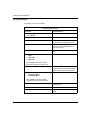
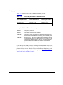
Text Conventions ...........................................................................................................xxvi
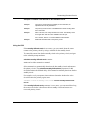
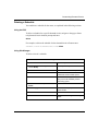
Acronyms ..................................................................................................................... xxviii
Hard-Copy Technical Manuals ........................................................................................xxx
How to Get Help .............................................................................................................xxx
Chapter 1
Dial Services Overview
How to Use This Guide ...................................................................................................1-2
Nortel Networks Dial Services ........................................................................................1-3
Network Access Methods and Services ...................................................................1-4
Dial-on-Demand Service ................................................................................................1-5
Activating Demand Circuits ......................................................................................1-5
Terminating Demand Circuits ...................................................................................1-6
Demand Lines and Pools .........................................................................................1-8
How Demand Lines, Pools, and Circuits Work Together ..........................................1-8
Demand Circuit Protocols ......................................................................................1-10
Configuring Frame Relay to Work Optimally with Dial-on-Demand .................1-11
Adding Bandwidth Service for Congested Demand Lines .....................................1-12
Dial Backup Service .....................................................................................................1-14
Activating the Backup Line .....................................................................................1-15
Reestablishing the Backup Connection ..................................................................1-15
Terminating the Backup Connection ......................................................................1-16
Backup Circuit Protocols ........................................................................................1-16
Knowing When the Primary Line Fails ...................................................................1-19
Backup Lines and Pools .........................................................................................1-20
How Backup Lines, Pools, and Circuits Work Together ..........................................1-20
Configuration of the Backup Circuit ........................................................................1-21
308621-14.00 Rev 00
v
Bandwidth-on-Demand Service ....................................................................................1-22
Enabling Bandwidth-on-Demand Service ..............................................................1-23
Activating Dial-Up Lines to Relieve Congestion .....................................................1-25
Terminating Secondary Lines .................................................................................1-25
Bandwidth-on-Demand Lines and Pools ................................................................1-25
How Lines, Pools, and Circuits Work Together .......................................................1-26
Sample Bandwidth-on-Demand Application ...........................................................1-27
Using the Same Line for All Dial Services ....................................................................1-27
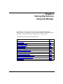
Chapter 2
Starting Dial Services Using Site Manager
Before You Begin ............................................................................................................2-2
Setting Up a Dial Service ...............................................................................................2-2
Configuring Line Pools ....................................................................................................2-6
Creating Line Pools with Modem Lines ....................................................................2-6
Creating Line Pools with ISDN Lines .......................................................................2-8
Configuring BRI Lines ..............................................................................................2-9
Configuring BRI Dial-Up Lines ...........................................................................2-9
Configuring BRI Leased Lines (Germany and Japan Only) ............................2-10
Configuring PRI Lines ............................................................................................2-11
Adding ISDN Lines to a Pool ..................................................................................2-13
Configuring Circuits ......................................................................................................2-14
Creating PPP Dial-on-Demand Circuits ........................................................................2-15
Specifying the Authentication Protocol Information ................................................2-16
Specifying the Connection Mode ...........................................................................2-17
Enabling a Protocol ................................................................................................2-18
Creating PPP Dial Backup Circuits ...............................................................................2-19
Specifying the Backup Mode ..................................................................................2-20
Specifying the Authentication Protocol Information ................................................2-21
Creating Bandwidth Circuits .........................................................................................2-22
Configuring Leased Circuits As Bandwidth Circuits ...............................................2-22
Specifying the Bandwidth Mode .............................................................................2-23
Specifying the Authentication Protocol Information ................................................2-25
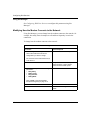
Adding Bandwidth Service for Demand Lines ........................................................2-26
Creating an Outgoing Phone List .................................................................................2-27
Creating the Local Phone List (ISDN Only) ..................................................................2-28
vi
308621-14.00 Rev 00
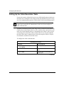
Setting Up the Caller Resolution Table .........................................................................2-30
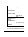
What to Do Next ...........................................................................................................2-31
Chapter 3
Starting Dial Services Using the BCC
Before You Begin ............................................................................................................3-2
Using the BCC ................................................................................................................3-2
BCC Help .................................................................................................................3-2
Specifying a Physical Interface for the ASN .............................................................3-3
Specifying a Physical Interface for the ARN .............................................................3-4
Demand Circuit Naming Conventions ................................................................3-4
Setting Up a Dial Service ...............................................................................................3-5
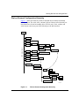
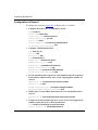
Dial-on-Demand Configuration Hierarchy ................................................................3-7
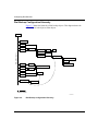
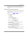
Dial Backup Configuration Hierarchy .......................................................................3-8
Creating a Leased Interface for Backup Service ............................................................3-9
Configuring a Modem Interface ....................................................................................3-10
Configuring an ISDN Interface ......................................................................................3-12
Configuring BRI Lines ............................................................................................3-12
Configuring PRI Lines ............................................................................................3-14
Designating an Interface As a Dial Object ....................................................................3-14
Creating a Line Pool .....................................................................................................3-15
Adding Lines to the Pool ...............................................................................................3-16
Specifying the ISDN Switch Type .................................................................................3-17
Configuring PPP Demand Circuits ...............................................................................3-18
Adding Protocols to the Demand Circuit ................................................................3-18
Defining the Circuit’s Connection Mode .................................................................3-19
Configuring PPP Backup Circuits .................................................................................3-19
Protocols for Backup Circuits .................................................................................3-20
Specifying the Authentication Protocol Information ......................................................3-20
Creating an Outgoing Phone List .................................................................................3-21
Creating the Local Phone List (ISDN Only) ..................................................................3-22
Setting Up the Caller Resolution Table .........................................................................3-24
What to Do Next ...........................................................................................................3-24
308621-14.00 Rev 00
vii
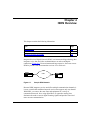
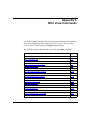
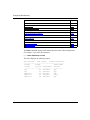
Chapter 4
ISDN Overview
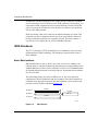
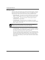
ISDN Standards ..............................................................................................................4-2
Basic Rate Interface .................................................................................................4-2
Primary Rate Interface .............................................................................................4-3
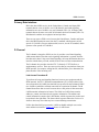
D Channel ................................................................................................................4-3
Link Access Procedure-D ..................................................................................4-3
Call Control on the D Channel ...........................................................................4-5
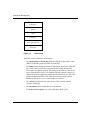
ISDN Interfaces ..............................................................................................................4-5
Functional Groups ....................................................................................................4-5
Reference Points ......................................................................................................4-6
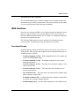
For More Information About ISDN ..................................................................................4-8
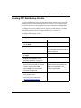
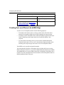
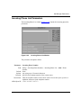
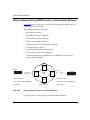
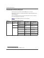
Chapter 5
Implementation Notes for All Dial Services
Point-to-Point Protocol ....................................................................................................5-1
PPP Authentication ..................................................................................................5-1
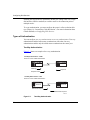
Types of Authentication ............................................................................................5-2
Two-Way Authentication .....................................................................................5-2
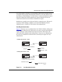
One-Way Authentication ....................................................................................5-3
Configuring the Type of Authentication ..............................................................5-4
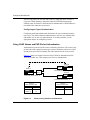
Using CHAP Names and PAP IDs for Authentication ...............................................5-4
WAN Encryption Protocol ...............................................................................................5-6
Using Encryption with Dial Backup ..........................................................................5-6
Asynchronous PPP .........................................................................................................5-6
Configuring Modems for Asynchronous PPP Interfaces ..........................................5-8
RADIUS ..........................................................................................................................5-9
RADIUS Authentication Services Using VSAs .........................................................5-9
ISDN Services ..............................................................................................................5-10
BRI Service on the AN, ANH, ASN, and ARN .......................................................5-11
B Channel Support ..........................................................................................5-11
D Channel Support ..........................................................................................5-11
BRI Leased-Line Operation for Germany and Japan ......................................5-12
BRI Subaddresses ...........................................................................................5-12
Floating B Option for the AN and ANH ............................................................5-12
PRI Service on the ASN, BLN, and BCN ...............................................................5-13
viii
308621-14.00 Rev 00
B Channel Support ..........................................................................................5-14
D Channel Support ..........................................................................................5-14
Selective PRI Service ......................................................................................5-14
PRI Multirate ....................................................................................................5-15
Placing Multirate Calls .....................................................................................5-15
Incoming Call Filtering ...........................................................................................5-16
Rate Adaption ........................................................................................................5-17
X.25 Service over an ISDN D Channel (BRI Only) ................................................5-18
Configuring X.25 Service over the D Channel .................................................5-19
Using the ping Command for ISDN Connections ...................................................5-20
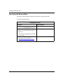
Chapter 6
Dial-on-Demand Implementation Notes
Bay Command Console ..................................................................................................6-1
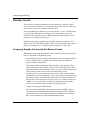
Standby Circuits .............................................................................................................6-2
Comparing Standby Circuits with Dial Backup Circuits ............................................6-2
How Standby Circuits Work ......................................................................................6-3
Balancing Traffic Between a Primary Circuit and a Hot Standby Circuit ..................6-4
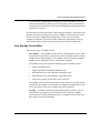
Callback ..........................................................................................................................6-5
Configuring Callback ................................................................................................6-6
Demand Circuit Groups ..................................................................................................6-7
Demand Pools and Demand Circuit Groups ............................................................6-7
Using Demand Circuit Groups with Dial Backup Service .........................................6-8
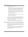
Managing Broadcast Traffic over Demand Circuits .........................................................6-8
Static Routes ............................................................................................................6-8
Dial-Optimized Routing ............................................................................................6-9
What Happens When You Enable Dial-Optimized Routing ................................6-9
Exceptions for Sending Routing Updates ........................................................6-10
Maintaining the Routing Table .........................................................................6-11
IP RIP Triggered Updates and Broadcast Timers ..................................................6-12
IPX RIP and SAP Broadcast Timers ......................................................................6-12
Traffic Filters ...........................................................................................................6-12
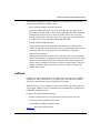
Data Compression ........................................................................................................6-13
PPP Multilink ................................................................................................................6-14
Protocol Prioritization ...................................................................................................6-15
308621-14.00 Rev 00
ix
Chapter 7
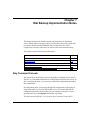
Dial Backup Implementation Notes
Bay Command Console ..................................................................................................7-1
Data Compression ..........................................................................................................7-2
Defining the Role of the Router in the Network ..............................................................7-2
Bandwidth for Backup Circuits ........................................................................................7-2
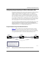
Using Unnumbered Interfaces to Dial an Alternative Site ...............................................7-3
Sample Network Using Unnumbered Interfaces ......................................................7-3
Simplifying Unnumbered Configurations with Demand Circuit Groups ....................7-4
Sample Network Using Demand Circuit Groups ......................................................7-5
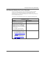
Chapter 8
Bandwidth-on-Demand Implementation Notes
Bandwidth-on-Demand Terminology ...............................................................................8-2
PPP Multilink ..................................................................................................................8-2
Multilink Fragmentation ............................................................................................8-4
PPP Bandwidth Allocation Protocol ................................................................................8-4
How BAP Works .......................................................................................................8-5
BAP Negotiation with Non-Nortel Networks Routers ...............................................8-6
Configuring BAP ......................................................................................................8-7
Data Compression ..........................................................................................................8-7
Protocol Prioritization .....................................................................................................8-8
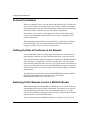
Defining the Role of the Router in the Network ..............................................................8-8
Balancing Traffic Between Lines in a Multilink Bundle ....................................................8-8
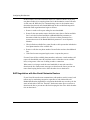
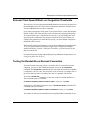
External Clock Speed Effects on Congestion Thresholds ..............................................8-9
Testing the Bandwidth-on-Demand Connection .............................................................8-9
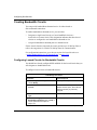
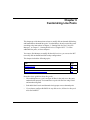
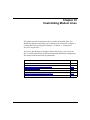
Chapter 9
Customizing Line Pools
Changing Pool IDs ..........................................................................................................9-2
Deleting Pools .................................................................................................................9-2
Modifying PPP Dial Interfaces in a Pool .........................................................................9-4
Setting a Time Limit for Convergence ......................................................................9-4
Specifying the Asynchronous Modem Control Character Map ................................9-5
Setting the Maximum Receive Unit (MRU) ...............................................................9-6
Disabling MRU Compliance .....................................................................................9-7
x
308621-14.00 Rev 00
Chapter 10
Customizing Modem Lines
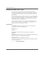
Modifying the WAN Interface Type ................................................................................10-2
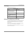
Modifying the Line Media Type and Cable Type ...........................................................10-3
Modifying the Line Priority ............................................................................................10-5
Modifying External Modem Configurations ...................................................................10-7
Using Modem Factory Defaults ..............................................................................10-7
Specifying a Modem Initialization Command (Hayes Only) ...................................10-8
Modifying the Modem Command String ...............................................................10-10
Changing the Asynchronous Baud Rate ..............................................................10-11
Modifying How the Modem Connects to the Network ..........................................10-12
Modifying the ARN Internal Modem Configuration .....................................................10-13
Selecting a Modem Type and Specifying an Initialization String ..........................10-13
Changing the Asynchronous Baud Rate ..............................................................10-15
Using Modem Factory Defaults ............................................................................10-15
Configuring a Modem for a Specific Country .......................................................10-17
Specifying the Phone Number to Dial ..................................................................10-17
Resetting the Modem Remotely ...........................................................................10-18
Modifying the Operation of the Modem ................................................................10-19
Deleting Modem Lines from a Pool .............................................................................10-20
Chapter 11
Customizing ISDN Lines
Modifying the MCT1 and MCE1 Port Configurations ....................................................11-2
Modifying the BRI and PRI Modes of Operation ...........................................................11-2
Configuring Selective PRI Service ................................................................................11-2
Modifying the ISDN Pool Channel Count ......................................................................11-3
Modifying the ISDN Channel Priority ............................................................................11-5
Modifying the ISDN Switch Type ...................................................................................11-6
Enabling Incoming Call Filtering ...................................................................................11-8
Modifying the Adaption Rate ........................................................................................11-9
Informing the Switch That Call Setup Is Complete .....................................................11-10
Configuring X.25 over a D Channel (BRI Only) ..........................................................11-11
Configuring the TEI Type ......................................................................................11-12
Configuring the TEI Value ....................................................................................11-13
Disabling X.25 over the D Channel ......................................................................11-14
308621-14.00 Rev 00
xi
Modifying BRI Signaling over the D Channel ..............................................................11-15
Modifying LAPD Transmission Units ....................................................................11-16
Activating ISDN S/T and U Interfaces ..................................................................11-16
Modifying the BRI T4 Timer .................................................................................11-17
Customizing Conformance Testing ......................................................................11-17
Modifying the BRI Line Configuration ...................................................................11-18
Modifying the X.25 Circuit for Service over the D Channel .........................................11-19
Modifying BRI Leased-Line Service (Germany and Japan Only) ...............................11-20
Changing the Circuit Name ..................................................................................11-20
Modifying the MTU ...............................................................................................11-20
Disabling the Leased Line ....................................................................................11-21
Modifying the BRI T4 Timer ........................................................................................11-21
Modifying the Interframe Time Fill Pattern ..................................................................11-22
Deleting BRI and PRI from the Router .......................................................................11-22
Deleting ISDN B Channels from a Pool ......................................................................11-23
Chapter 12
Customizing Demand Circuits
Adding Frame Relay Demand Circuits ..........................................................................12-2
Modifying the Frame Relay Interface ............................................................................12-3
Adding a Service Record .......................................................................................12-5
Adding or Modifying PVCs .....................................................................................12-6
Adding Layer 3 Protocols to Frame Relay Demand Circuits ..................................12-7
Customizing Demand Circuit Operation .......................................................................12-8
Forcing the Circuit to Activate or Deactivate ..........................................................12-8
Deactivating the Circuit Due to Inactivity ................................................................12-9
Retrying the Connection ......................................................................................12-11
Specifying Which Router Initiates a Call ..............................................................12-12
Terminating a Failed Connection and Using Another Connection ........................12-14
Modifying PPP Authentication Information ...........................................................12-15
Changing the Authentication Protocol ...........................................................12-16
Modifying CHAP ............................................................................................12-16
Modifying PAP ................................................................................................12-16
Configuring Outbound Authentication ............................................................12-17
Specifying the Duration of the Circuit ...................................................................12-19
Specifying the Maximum and Minimum Time the Circuit Is Active ................12-19
xii
308621-14.00 Rev 00
Terminating and Resetting the Circuit ............................................................12-20
Setting the Inactivity Mode ...................................................................................12-22
Changing the Demand Circuit Name ...................................................................12-23
Enabling Dial-Optimized Routing .........................................................................12-24
Configuring Standby Circuits ................................................................................12-26
Guidelines for Configuring Standby Circuits ..................................................12-26
Configuring a Hot Standby Circuit .................................................................12-27
Configuring a Normal Standby Circuit ...........................................................12-28
Controlling the Failback to the Primary Circuit ...............................................12-28
Controlling the Standby Circuit Manually .......................................................12-29
Enabling Callback ................................................................................................12-31
Modifying the Callback Mode Parameter .......................................................12-31
Callback and the Circuit’s Connection Mode .................................................12-32
Configuring Server and Client Delays ............................................................12-34
Choosing the Severity Level for Error Messages .................................................12-35
Adding Bandwidth Service for Demand Lines (PPP Only) .........................................12-36
Adding Layer 3 Protocols to PPP Demand Circuits ....................................................12-36
Scheduling Demand Circuit Availability ......................................................................12-37
Scheduling PPP Standby Circuits ........................................................................12-41
Using Schedules to Manage Standby Circuit Availability ...............................12-41
Configuring Multiple Time of Day Schedules .................................................12-41
Deleting a Schedule .............................................................................................12-45
Configuring Demand Circuit Groups ...........................................................................12-46
Protocol Configuration for Demand Circuit Groups ..............................................12-47
Caller Resolution Information for Demand Circuit Groups ...................................12-47
Modifying the Demand Circuit Group Configuration .............................................12-49
Modifying the Number of Circuits in a Demand Circuit Group .......................12-49
Modifying the Demand Pool That the Demand Circuit Group Uses ..............12-50
Removing a Demand Circuit Group ...............................................................12-51
Removing Demand Circuits ........................................................................................12-52
Deleting Hot Standby Circuits ..............................................................................12-53
Chapter 13
Customizing Backup Circuits
Creating a PPP Backup Circuit for a Direct Mode PVC ................................................13-2
Creating Frame Relay Backup Circuits for Group Mode PVCs .....................................13-5
308621-14.00 Rev 00
xiii
Modifying the Frame Relay Backup Interface .........................................................13-6
Modifying Frame Relay Service Records ...............................................................13-7
Configuring Filters for Backup Configurations ........................................................13-9
Configuring Filters for Primary/Secondary Interfaces ......................................13-9
Configuring Filters for Primary/Shared Interfaces ...........................................13-9
Customizing PPP and Frame Relay Backup Circuits ..................................................13-10
Modifying Which Router Initiates a Call ...............................................................13-10
Modifying PPP Authentication Information ...........................................................13-11
Changing the Authentication Protocol ...........................................................13-11
Configuring CHAP .........................................................................................13-12
Configuring PAP ............................................................................................13-12
Configuring Outbound Authentication ............................................................13-13
Customizing the Duration of the Circuit ................................................................13-14
Modifying the Activation of a Backup Circuit ........................................................13-15
Enabling Filters for Backup Circuits (Frame Relay Only) .....................................13-16
Specifying the Redial Count .................................................................................13-17
Specifying the Time Between Calls ......................................................................13-17
Choosing the Severity Level for Error Messages .................................................13-18
Scheduling Backup Circuit Availability ........................................................................13-18
Deleting a Backup Circuit Schedule .....................................................................13-21
Removing PPP or Frame Relay Backup Service ........................................................13-22
Chapter 14
Customizing Bandwidth-on-Demand Circuits
Customizing Bandwidth-on-Demand Service ...............................................................14-2
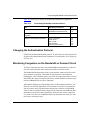
Changing the Authentication Protocol ..........................................................................14-3
Monitoring Congestion on the Bandwidth or Demand Circuit .......................................14-3
Bandwidth-on-Demand Congestion Monitor Parameters .......................................14-4
Setting the Preferred and Reserved Slots ..............................................................14-6
Setting the Preferred and Reserved Slots for BAP ................................................14-6
Modifying Multilink Fragmentation ..........................................................................14-7
Enabling BAP for Bandwidth-on-Demand Service ........................................................14-8
Removing Bandwidth-on-Demand Service ...................................................................14-9
xiv
308621-14.00 Rev 00
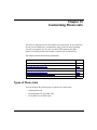
Chapter 15
Customizing Phone Lists
Types of Phone Lists ....................................................................................................15-1
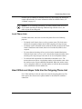
How ISDN Calls Use Phone Lists .................................................................................15-2
Outgoing and Incoming Phone Lists ......................................................................15-2
Local Phone Lists ...................................................................................................15-3
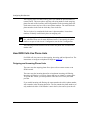
How V.25bis and Hayes Calls Use the Outgoing Phone List ........................................15-3
Modifying an Outgoing Phone List ................................................................................15-4
Adding Phone Numbers .........................................................................................15-4
Modifying the Phone Number Type ........................................................................15-7
Specifying the ISDN Number Type and Plan ...................................................15-8
Reordering and Deleting Phone Numbers ...........................................................15-10
Modifying a Call’s Adaption Rate .........................................................................15-12
Changing the Remote Pool Type ..........................................................................15-13
Configuring the Phone Number for Single or Multiple Calls .................................15-15
Enabling PRI Multirate .........................................................................................15-16
Changing the AT Command String (Hayes Only) .................................................15-18
Creating an Incoming Phone List (ISDN Only) ...........................................................15-19
Modifying Numbers in the Incoming Phone List ...................................................15-21
Using the Incoming Phone List for Callback Service ...........................................15-22
Creating a Local Phone List (ISDN Only) ...................................................................15-23
Modifying the Local Phone List ............................................................................15-26
Chapter 16
Customizing Caller Resolution
Caller Resolution for Demand Circuit Groups ...............................................................16-2
Adding Entries to the Caller Resolution Table ..............................................................16-3
Configuring the CHAP Secret ................................................................................16-4
Configuring the PAP Password ...............................................................................16-4
Modifying Entries in the Caller Resolution Table ..........................................................16-6
Deleting a Caller Resolution Entry ...............................................................................16-7
Appendix A
Site Manager Parameters
Pool ID Parameter ......................................................................................................... A-4
WAN Serial Interface Type Parameter ........................................................................... A-5
Sync and Async Line Media Type Parameters .............................................................. A-6
308621-14.00 Rev 00
xv
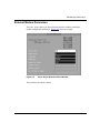
External Modem Parameters ......................................................................................... A-9
V.34 Modem Parameters ............................................................................................. A-15
Port Application Mode Parameters .............................................................................. A-18
PRI Port Application Mode Parameter .................................................................. A-18
BRI Port Application Mode Parameter .................................................................. A-19
ISDN Switch Parameters ............................................................................................. A-20
Pool Channel Count and Priority Parameters .............................................................. A-24
BRI Configuration Parameters ..................................................................................... A-27
BRI Leased-Line Configuration Parameters ................................................................ A-32
Demand Circuit Parameters (PPP and Frame Relay) .................................................. A-34
Standby Circuit Parameters (PPP Demand Circuits Only) .......................................... A-41
Callback Parameters (PPP Demand Circuits Only) ..................................................... A-43
Authentication Protocol Parameters ............................................................................ A-46
Circuit Duration Parameters (Demand and Dial Backup) ............................................ A-51
Circuit Schedule Parameters (Demand and Dial Backup) ........................................... A-55
Demand Circuit Group Parameters ............................................................................. A-62
Demand Circuit Group Protocol Parameters ............................................................... A-63
Caller Resolution Info Parameters (Demand Circuit Groups) ...................................... A-65
PPP Circuit Options Parameters (Dial Backup) ........................................................... A-67
PPP Primary Circuit Definition Parameters (Dial Backup) ........................................... A-69
Frame Relay Interface Parameters (Dial Backup) ........................................................ A-71
Frame Relay Primary Interface Definition Parameters (Dial Backup) .......................... A-74
Frame Relay Service Control Parameter (Demand and Dial Backup) ......................... A-76
Frame Relay PVC and Service Parameters (Demand and Dial Backup) .................... A-77
Bandwidth-on-Demand Circuit Options Parameters .................................................... A-77
Bandwidth-on-Demand Circuit Definition Parameters ................................................. A-80
Bandwidth-on-Demand Congestion Monitor and BAP Parameters ............................. A-82
Local Phone Number Parameters ............................................................................... A-90
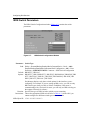
Outgoing Phone List Parameters ................................................................................. A-94
Incoming Phone List Parameters ............................................................................... A-105
Caller Resolution Table Parameters .......................................................................... A-107
Appendix B
Configuration Examples
Dial-on-Demand with PPP ............................................................................................. B-2
Configuring Dial-on-Demand Using the BCC .......................................................... B-3
xvi
308621-14.00 Rev 00
Configuration of Router 4 ................................................................................. B-3
Configuration of Router 7 ................................................................................. B-4
Configuring Dial-on-Demand Using Site Manager .................................................. B-6
Demand Pool Configuration .............................................................................. B-6
Demand Circuit Configuration .......................................................................... B-7
Outgoing Phone List Configuration ................................................................... B-8
Caller Resolution Table Configuration .............................................................. B-9
Dial-on-Demand Using ISDN Lines in a Frame Relay Network ................................... B-10
Configuration of Router 1 ...................................................................................... B-11
Configuration of Router 2 ...................................................................................... B-12
Dial-on-Demand for an ISDN Network ......................................................................... B-14
Configuration of Routers 1 and 2 .......................................................................... B-15
Port Application Mode Configuration .............................................................. B-15
Demand Pool Configuration ............................................................................ B-16
Demand Circuit Configuration ........................................................................ B-17
Outgoing Phone List Configuration ................................................................. B-18
Protocol Configuration .................................................................................... B-19
Caller Resolution Table Configuration ............................................................ B-19
Local Phone Number Configuration ............................................................... B-20
Configuring a Hot Standby Circuit for a Frame Relay Network .................................... B-21
Configuration of Router 1 ...................................................................................... B-22
Configuration of Router 2 (Normal Standby Circuit) .............................................. B-23
Dial Backup with PPP or Standard on the Primary Line .............................................. B-24
Configuring Dial Backup Using the BCC ............................................................... B-25
Configuration of Router 1 ............................................................................... B-25
Optional Schedule Configuration for Router 1 ................................................ B-26
Configuration of Router 2 ............................................................................... B-27
Configuring Dial Backup Using Site Manager ....................................................... B-28
Leased Interface Configuration ....................................................................... B-28
Backup Pool Configuration ............................................................................. B-29
Backup Circuit Configuration .......................................................................... B-30
Outgoing Phone List Configuration ................................................................. B-31
Caller Resolution Table Configuration ............................................................ B-31
Dial Backup over an ISDN Network ............................................................................. B-33
Configuring Dial Backup Using the BCC ............................................................... B-34
308621-14.00 Rev 00
xvii
Configuration of Router 1 ............................................................................... B-34
Configuration of Router 2 ............................................................................... B-36
Configuring Dial Backup Using Site Manager ....................................................... B-37
Leased Interface Configuration ....................................................................... B-37
Port Application Mode Configuration .............................................................. B-39
Backup Pool Configuration ............................................................................. B-39
Backup Circuit Configuration .......................................................................... B-40
Outgoing Phone List Configuration ................................................................. B-41
Caller Resolution Table Configuration ............................................................ B-41
Local Phone Number Configuration ............................................................... B-43
Appendix C
BCC show Commands
Online Help for show Commands .................................................................................. C-3
Commands for Dial-on-Demand .................................................................................... C-4
show dial demand summary .......................................................................................... C-5
show dial demand pools ................................................................................................ C-5
show dial demand circuits general ................................................................................. C-7
show dial demand circuits advanced ............................................................................. C-7
show dial demand lines ................................................................................................. C-8
show dial demand schedules ........................................................................................ C-9
show dial demand in-phone-numbers .......................................................................... C-10
show dial demand out-phone-numbers ....................................................................... C-10
show dial demand caller-resolution ............................................................................. C-11
show dial demand pap-chap-information ..................................................................... C-12
Commands for Dial Backup ......................................................................................... C-13
show dial backup summary ......................................................................................... C-13
show dial backup pools ................................................................................................ C-14
show dial backup circuits ............................................................................................. C-15
show dial backup lines ................................................................................................. C-16
show dial backup schedules ........................................................................................ C-17
show dial backup out-phone-numbers ......................................................................... C-17
show dial backup caller-resolution ............................................................................... C-18
show dial backup pap-chap-information ...................................................................... C-19
Commands for All Dial Services .................................................................................. C-20
show dial calls ............................................................................................................. C-21
xviii
308621-14.00 Rev 00
show dial caller-resolution ........................................................................................... C-22
show dial pap-chap-information ................................................................................... C-22
show dial local-phone-numbers ................................................................................... C-23
Modem Commands ..................................................................................................... C-24
show modem alerts ..................................................................................................... C-24
show modem all ........................................................................................................... C-25
show modem errors ..................................................................................................... C-28
show modem sample ................................................................................................... C-29
show modem stats ....................................................................................................... C-30
Appendix D
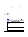
Ordering ISDN Lines in the United States
Ordering BRI Lines ........................................................................................................ D-1
Ordering PRI Lines ........................................................................................................ D-2
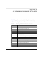
Appendix E
AT Initialization Commands for the ARN
Index
308621-14.00 Rev 00
xix
Figures
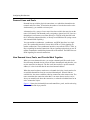
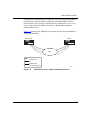
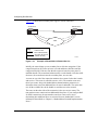
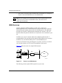
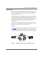
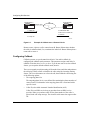
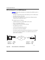
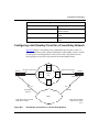
Figure 1-1.
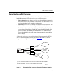
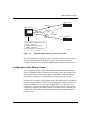
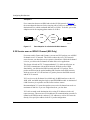
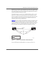
Example of Dial Access to a Switched Telephone Network .....................1-3
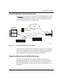
Figure 1-2.
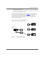
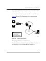
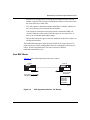
Dial-on-Demand Service ..........................................................................1-7
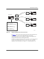
Figure 1-3.
Example of Demand Lines, Pools, and Circuits .......................................1-9
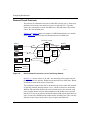
Figure 1-4.
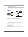
Dial-on-Demand Connection over a Frame Relay Network ...................1-10
Figure 1-5.
Additional Lines for a Dial-on-Demand Connection ...............................1-13
Figure 1-6.
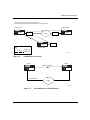
PPP Backup over a PSTN .....................................................................1-17
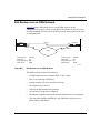
Figure 1-7.
PPP Backup over an ISDN Network ......................................................1-17
Figure 1-8.
Link Backup for a Frame Relay Network ................................................1-18
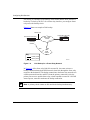
Figure 1-9.
Example of Backup Pools, Lines, and Circuits .......................................1-21
Figure 1-10. Example of Bandwidth-on-Demand Service ..........................................1-24
Figure 1-11. Sample Bandwidth-on-Demand Network ...............................................1-27
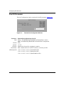
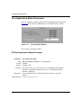
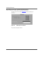
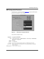
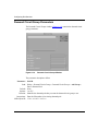
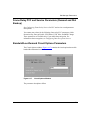
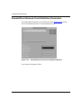
Figure 2-1.
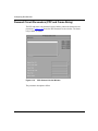
Dialup Menu in the Configuration Manager Window ................................2-5
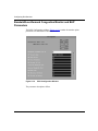
Figure 3-1.
Dial-on-Demand Configuration Hierarchy ................................................3-7
Figure 3-2.
Dial Backup Configuration Hierarchy .......................................................3-8
Figure 4-1.
Sample ISDN Network .............................................................................4-1
Figure 4-2.
BRI Interface ............................................................................................4-2
Figure 4-3.
LAPD Frame ............................................................................................4-4
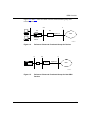
Figure 4-4.
Reference Points and Functional Groups for Devices ..............................4-7
Figure 4-5.
Reference Points and Functional Groups for Non-ISDN Devices ............4-7
Figure 5-1.
Two-Way Authentication ...........................................................................5-2
Figure 5-2.
One-Way Authentication ..........................................................................5-3
Figure 5-3.
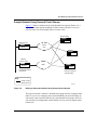
Routers Using CHAP for Authentication ..................................................5-4
Figure 5-4.
Using Asynchronous PPP over Modem Lines .........................................5-7
Figure 5-5.
Router in an ISDN Network ....................................................................5-10
Figure 5-6.
Rate Adaption for a Network with a 56 Kb/s Trunk Line .........................5-17
Figure 5-7.
Rate Adaption for a Switched 56 Kb/s Network .....................................5-18
Figure 5-8.
X.25 over the D Channel ........................................................................5-19
Figure 6-1.
Example of Callback over a Demand Circuit ............................................6-6
Figure 7-1.
Dialing an Alternative Router Using Unnumbered IP Interfaces ..............7-3
308621-14.00 Rev 00
xxi
Figure 7-2.
Dialing an Alternative Router Using Demand Circuit Groups ..................7-5
Figure 8-1.
Multilink and Bandwidth-on-Demand Operation ......................................8-3
Figure 8-2.
BAP Negotiation Between Two Routers ...................................................8-5
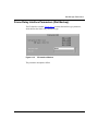
Figure A-1.
Demand Pool Configuration Window ...................................................... A-4
Figure A-2.
Choose WAN Serial Interface Type Window ........................................... A-5
Figure A-3.
Sync Line Media Type Window ............................................................... A-6
Figure A-4.
Async Line Media Type Window ............................................................. A-6
Figure A-5.
Async Hayes Modem Interface Window .................................................. A-9
Figure A-6.
Port Application Window ....................................................................... A-18
Figure A-7.
ISDN Switch Configuration Window ...................................................... A-20
Figure A-8.
ISDN Logical Lines Window .................................................................. A-24
Figure A-9.
BRI Interface Configuration Window ..................................................... A-27
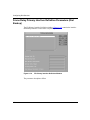
Figure A-10. PPP Demand Circuits Window ............................................................. A-34
Figure A-11. Circuit Time of Day Schedule Window .................................................. A-55
Figure A-12. Demand Circuit Groups Window ........................................................... A-62
Figure A-13. Circuit Options Window ......................................................................... A-67
Figure A-14. Primary Circuit Definition Window ........................................................ A-69
Figure A-15. FR Interface Window ............................................................................. A-71
Figure A-16. FR Primary Interface Definition Window ............................................... A-74
Figure A-17. Circuit Options Window ......................................................................... A-77
Figure A-18. Bandwidth-on-Demand Circuit Definition Window ................................ A-80
Figure A-19. BOD Configuration Window .................................................................. A-82
Figure A-20. ISDN Local Phone Numbers Window ................................................... A-90
Figure A-21. Outgoing Phone List Window ................................................................ A-94
Figure A-22. Incoming Phone List Window .............................................................. A-105
Figure A-23. Caller Resolution Table Window ......................................................... A-107
xxii
Figure B-1.
Dial-on-Demand Configuration with PPP ................................................ B-2
Figure B-2.
Dial-on-Demand Across a Frame Relay Network ................................. B-10
Figure B-3.
Dial-on-Demand for an ISDN Network .................................................. B-14
Figure B-4.
Hot Standby Connections in a Frame Relay Network ........................... B-21
Figure B-5.
Dial Backup Configuration with PPP ..................................................... B-24
Figure B-6.
Dial Backup over an ISDN Network ...................................................... B-33
308621-14.00 Rev 00
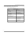
Tables
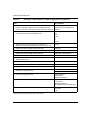
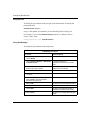
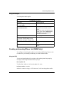
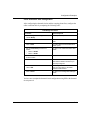
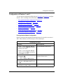
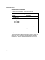
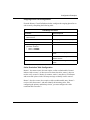
Table 1-1.
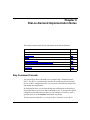
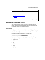
Dial Service Names .................................................................................1-2
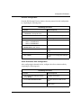
Table 1-2.
Primary and Backup Lines .....................................................................1-14
Table 1-3.
Primary and Backup Circuit Protocols ...................................................1-15
Table 2-1.
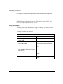
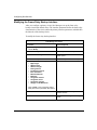
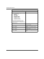
Setting Up a Default Modem or ISDN Configuration Using Site Manager 2-4
Table 3-1.
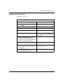
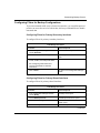
Setting Up a Default Modem or ISDN Configuration Using the BCC .......3-6
Table 3-2.
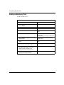
Mode Types for BRI Operation ...............................................................3-13
Table 7-1.
Configuration Requirements for Routers A and C ....................................7-4
Table 8-1.
Terminology for Bandwidth-on-Demand Service ......................................8-2
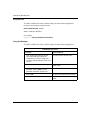
Table 12-1.
Callback Mode Options ........................................................................12-33
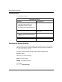
Table 12-2.
Scheduling Options ..............................................................................12-38
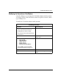
Table 12-3.
Time of Day Schedules for Standby Circuit 1 ......................................12-42
Table 13-1.
Dial Backup Configurations ....................................................................13-2
Table 13-2.
Scheduling Options ..............................................................................13-18
Table 14-1.
Terminology for Bandwidth-on-Demand Service ....................................14-2
Table 14-2.
Customizing Bandwidth-on-Demand Service ........................................14-3
Table 14-3.
Changing the Monitor Parameters .........................................................14-5
Table 15-1.
Phone Number Type Options .................................................................15-7
Table A-1.
Organization of Parameters .................................................................... A-1
Table A-2.
Abbreviated Site Manager Window Titles ............................................... A-2
Table A-3.
Switch Types by Country ....................................................................... A-21
Table C-1.
Dial-on-Demand show Commands ......................................................... C-4
Table C-2.
Dial Backup show Commands .............................................................. C-13
Table C-3.
Dial show Commands for All Services .................................................. C-20
Table C-4.
Modem show Commands ..................................................................... C-24
Table D-1.
BRI Parameters for the AT&T 5ESS Switch ............................................ D-1
Table D-2.
BRI Parameters for the Nortel Networks DMS-100 Switch ..................... D-2
Table E-1.
Summary of AT Modem Initialization Commands ................................... E-1
308621-14.00 Rev 00
xxiii
Preface
This guide describes dial-on-demand, dial backup, and bandwidth-on-demand
services and what you do to start and customize these dial services on a Nortel
Networks™ router.
You can use the Bay Command Console (BCC™) or Site Manager to configure
dial-on-demand and dial backup on a router. You use Site Manager to configure
bandwidth-on-demand. In this guide, you will find instructions for using both the
BCC and Site Manager.
Before You Begin
Before using this guide, you must complete the following procedures. For a new
router:
•
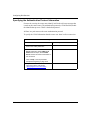
Install the router (see the installation guide that came with your router).
•
Connect the router to the network and create a pilot configuration file (see
Quick-Starting Routers, Configuring BayStack Remote Access, or Connecting
ASN Routers to a Network).
Make sure that you are running the latest version of Nortel Networks BayRS™ and
Site Manager software. For information about upgrading BayRS and Site
Manager, see the upgrading guide for your version of BayRS.
308621-14.00 Rev 00
xxv
Configuring Dial Services
Text Conventions
This guide uses the following text conventions:
angle brackets (< >)
Indicate that you choose the text to enter based on the
description inside the brackets. Do not type the
brackets when entering the command.
Example: If the command syntax is:
ping <ip_address>, you enter:
ping 192.32.10.12
bold text
Indicates command names and options and text that
you need to enter.
Example: Enter show ip {alerts | routes}.
Example: Use the dinfo command.
braces ({})
Indicate required elements in syntax descriptions
where there is more than one option. You must choose
only one of the options. Do not type the braces when
entering the command.
Example: If the command syntax is:
show ip {alerts | routes}, you must enter either:
show ip alerts or show ip routes, but not both.
brackets ([ ])
Indicate optional elements in syntax descriptions. Do
not type the brackets when entering the command.
Example: If the command syntax is:
show ip interfaces [-alerts], you can enter either:
show ip interfaces or show ip interfaces -alerts.
ellipsis points (. . . )
Indicate that you repeat the last element of the
command as needed.
Example: If the command syntax is:
ethernet/2/1 [<parameter> <value>] . . . , you enter
ethernet/2/1 and as many parameter-value pairs as
needed.
xxvi
308621-14.00 Rev 00
Preface
italic text
Indicates file and directory names, new terms, book
titles, and variables in command syntax descriptions.
Where a variable is two or more words, the words are
connected by an underscore.
Example: If the command syntax is:
show at <valid_route>
valid_route is one variable and you substitute one value
for it.
screen text
Indicates system output, for example, prompts and
system messages.
Example: Set Trap Monitor Filters
separator ( > )
Shows menu paths.
Example: Protocols > IP identifies the IP option on the
Protocols menu.
vertical line ( | )
Separates choices for command keywords and
arguments. Enter only one of the choices. Do not type
the vertical line when entering the command.
Example: If the command syntax is:
show ip {alerts | routes}, you enter either:
show ip alerts or show ip routes, but not both.
308621-14.00 Rev 00
xxvii
Configuring Dial Services
Acronyms
This guide uses the following acronyms:
xxviii
ANI
Automatic Number Identification
ARP
Address Resolution Protocol
AURP
AppleTalk Update-based Routing Protocol
BACP
Bandwidth Allocation Control Protocol
BAP
Bandwidth Allocation Protocol
BofL
Breath of Life
BRI
basic rate interface
CHAP
Challenge Handshake Authentication Protocol
CRC
cyclic redundancy check
CSU
channel service unit
DLCI
data link connection identifier
DLCMI
data link control management interface
DSL
Digital Subscriber Loop
DSU
data service unit
ET
exchange terminator
HDLC
High-level Data Link Control
ICMP
Internet Control Message Protocol
IFTF
interframe time fill
IP
Internet Protocol
IPX
Internetwork Packet Exchange
ISDN
Integrated Services Digital Network
ITU-T
International Telecommunication
Union-Telecommunication Standardization Sector
(formerly CCITT)
LAN
local area network
LAPD
Link Access Procedure Digital
LCP
Link Control Protocol
308621-14.00 Rev 00
Preface
LQR
Link Quality Report
LT
line terminator
MIB
management information base
MRU
maximum receive unit
NCP
Network Control Protocol
NT
network terminator
PAP
Password Authentication Protocol
PH
packet handling
PPP
Point-to-Point Protocol
PRI
primary rate interface
PSPDN
packet-switched Public Data Network
PSTN
public-switched telephone network
PVC
permanent virtual circuit
RADIUS
Remote Authentication Dial-In User Service
RIP
Routing Information Protocol
SAP
Service Advertising Protocol
SAPI
service access point identifier
SCC
serial communication controller
SPID
Service Profile Identifier
SVC
switched virtual circuit
TA
terminal adapter
TE
terminal equipment
TEI
terminal endpoint identifier
UNI
user-to-network interface
VSA
vendor-specific attribute
WAN
wide area network
XNS
Xerox Network System
308621-14.00 Rev 00
xxix
Configuring Dial Services
Hard-Copy Technical Manuals
You can print selected technical manuals and release notes free, directly from the
Internet. Go to support.baynetworks.com/library/tpubs/. Find the product for
which you need documentation. Then locate the specific category and model or
version for your hardware or software product. Using Adobe Acrobat Reader, you
can open the manuals and release notes, search for the sections you need, and print
them on most standard printers. You can download Acrobat Reader free from the
Adobe Systems Web site, www.adobe.com.
You can purchase selected documentation sets, CDs, and technical publications
through the collateral catalog. The catalog is located on the World Wide Web at
support.baynetworks.com/catalog.html and is divided into sections arranged
alphabetically:
•
The “CD ROMs” section lists available CDs.
•
The “Guides/Books” section lists books on technical topics.
•
The “Technical Manuals” section lists available printed documentation sets.
How to Get Help
If you purchased a service contract for your Nortel Networks product from a
distributor or authorized reseller, contact the technical support staff for that
distributor or reseller for assistance.
If you purchased a Nortel Networks service program, contact one of the following
Nortel Networks Technical Solutions Centers:
xxx
Technical Solutions Center
Telephone Number
Billerica, MA
800-2LANWAN (800-252-6926)
Santa Clara, CA
800-2LANWAN (800-252-6926)
Valbonne, France
33-4-92-96-69-68
Sydney, Australia
61-2-9927-8800
Tokyo, Japan
81-3-5402-7041
308621-14.00 Rev 00
Chapter 1
Dial Services Overview
A dial service connects remote users through a central switched network to other
destinations on the network using dial-up lines (also called switched lines).
Dial-up lines are temporary connections that a router activates when there is data
to send across the network, when a failed connection needs a backup connection,
or when a congested leased line needs an additional connection for more
bandwidth.
For remote users such as people in branch offices, telecommuters, and sales
people in the field, dial-up lines can be a cost-effective alternative to leased lines
and packet networks, which are permanent connections that are available
regardless of network traffic.
Nortel Networks offers three dial services: dial-on-demand, dial backup, and
bandwidth-on-demand. This chapter includes the following information:
Topic
Page
How to Use This Guide
1-2
Nortel Networks Dial Services
1-3
Dial-on-Demand Service
1-5
Dial Backup Service
1-14
Bandwidth-on-Demand Service
1-22
Using the Same Line for All Dial Services
1-27
Chapters 5 through 8 describe the Nortel Networks implementation of each dial
service.
308621-14.00 Rev 00
1-1
Configuring Dial Services
How to Use This Guide
This guide is organized as follows:
•
Overview of each dial service.
If you are new to Nortel Networks dial services, begin with this chapter. If not,
go to one of the starting chapters.
•
Starting chapters, which explain how to set up a basic configuration using all
of the defaults.
Go to Chapter 2 to start any dial service using Site Manager, the graphical
user interface network management tool. Go to Chapter 3 to start
dial-on-demand or dial backup service using the Bay Command Console
(BCC), the command-line interface configuration tool.
•
Chapters describing features specific to each dial service.
Read Chapters 5, 6, 7, and 8 to learn about the Nortel Networks
implementation of dial service features.
•
Instructions for modifying the default configuration that you set up based on
the instructions in Chapter 2 or 3.
To customize a dial service configuration, see Chapters 9 through 16. Most of
the instructions assume that you created an initial configuration as described
in Chapter 2 or 3.
•
Appendixes for Site Manager parameter descriptions, configuration examples,
BCC show commands, ISDN ordering information, and a list of AT modem
initialization commands.
The names of the dial services are sometimes abbreviated in this guide. Table 1-1
lists the full and abbreviated names of each dial service.
Table 1-1.
1-2
Dial Service Names
Full Name
Abbreviated Name
Dial-on-demand
Demand
Dial backup
Backup
Bandwidth-on-demand
Bandwidth
308621-14.00 Rev 00
Dial Services Overview
Nortel Networks Dial Services
The router provides three types of dial services: dial-on-demand, dial backup, and
bandwidth-on-demand. Each dial service serves a different purpose:
•
Dial-on-demand service reduces your line costs by establishing a connection
between two devices only when there is data to send. You do not incur the cost
of a leased line that is active regardless of data traffic.
•
Dial backup service provides a backup circuit when a leased circuit fails. The
backup circuit serves as an alternative path for data to reach its destination.
•
Bandwidth-on-demand service provides up to 29 additional B channels for a
congested leased line, dial-on-demand line, or leased multilink bundle. This
provides a total of 30 B channels for communication. The additional lines
increase bandwidth for data traffic, improving communication and reducing
network delays.
All three dial services work over public-switched telephone networks (PSTNs)
such as a standard telephone network, a switched 56 Kb/s network, and an
Integrated Services Digital Network (ISDN) (Figure 1-1).
PSTN
line
ial-up
1
D
Modem
DSU/CSU
Dial-up line 2
Terminal
adapter*
Dial-u
Router
p line
Dial-
Switched
56 Kb/s
network
3
up lin
e4
ISDN
*You only need a terminal adapter if your router does not have built-in ISDN capability.
If your router has an ISDN BRI module or an MCT1 or MCE1 link module installed,
along with ISDN software, you can connect to an ISDN network directly.
DS0005A
Figure 1-1.
308621-14.00 Rev 00
Example of Dial Access to a Switched Telephone Network
1-3
Configuring Dial Services
Network Access Methods and Services
The router initiates, monitors, and terminates dial-up connections using a modem
or ISDN terminal adapter that supports Raise DTR, V.25bis, or Hayes signaling,
or a router with a built-in ISDN interface connected directly to an ISDN network.
If the router has internal ISDN capability, you do not need external dial devices.
Note: For Basic Rate Interface (BRI) service, you need a network terminator 1
(NT1) to connect to an ISDN network. The router’s ISDN/BRI adapter module
does not include an internal NT1, so you or your service provider must supply it.
For the ARN™, the ISDN/BRI S/T adapter module does not have an NT1, so you
or your service provider must supply it. The ARN ISDN/BRI U adapter module
has the NT1 built in.
All three dial services can access a switched network using the following
methods:
1-4
•
Integrated ISDN capability -- Provides a BRI or Primary Rate Interface
(PRI) for digital connectivity from the router to the destination device,
replacing standard analog phone lines. Using signals on an ISDN line, the
router instructs the network to set up a call to a particular destination. ISDN
capability eliminates the need for dial devices such as modems, because you
no longer need to convert digital signals to analog. An ISDN network also
allows you to send data, voice, and video over the same digital line.
•
Raise DTR -- A signaling method that enables access to the network by
preprogramming the destination phone numbers into the dial device (modem
or ISDN terminal adapter). Raise DTR signaling works with the following
interfaces: X.21, V.35, RS-232, and RS-422.
•
V.25bis -- A signaling method that enables access to the network by passing
the destination phone numbers from the router to the dial device (modem or
ISDN terminal adapter). This method lets the dial device support connections
to multiple destinations. V.25bis signaling works with the following
interfaces: X.21, V.35, RS-232, and RS-422.
•
Hayes -- A signaling method that enables network access by passing the
destination phone numbers from the router to the dial device (modem or ISDN
terminal adapter). Using Hayes signaling, the router sends an AT initialization
command to interact with the dial device. The ARN internal V.34 modem uses
Hayes signaling.
308621-14.00 Rev 00
Dial Services Overview
The method you choose depends on your application, network resources, and the
type of network to which you are connecting. ISDN, a complex networking
technology, is further explained in Chapter 4.
Dial-on-Demand Service
Dial-on-demand service enables you to establish a network connection only when
the router has data to send across the network, or when you dynamically configure
the router to establish a connection. By using dial-up lines, you significantly
reduce the high costs associated with leased lines, which connect remote locations
even if there is no data to transmit or receive.
Activating Demand Circuits
To implement dial-on-demand, the router establishes a demand circuit. The router
activates a demand circuit when:
•
The router has data to send across the circuit.
When the router has data to transmit, it automatically selects one of the
demand lines from the circuit’s associated demand pool. As long as data is
going across the line, the end-to-end connection remains active.
•
You enable the Force Dial parameter, which instructs the router to force a
connection.
To activate a line immediately, you configure the Force Dial parameter to
force the router to initiate a connection, regardless of whether there is data
activity. To configure this parameter, see “Forcing the Circuit to Activate or
Deactivate” on page 12-8.
•
You specify a time of day to activate the circuit.
Using the Schedule option, you can schedule the circuit’s availability for a
specific day and time. The schedule parameters are part of the circuit’s
configuration (see “Scheduling Demand Circuit Availability” on page 12-37).
The Schedule option also allows you to specify whether the router uses the
Inactivity Timeout parameter to dynamically deactivate the connection.
The router does not accept incoming calls or activate frame relay demand circuits
if there is an incoming call from the frame relay network. The router answers an
incoming call only over a PPP circuit.
308621-14.00 Rev 00
1-5
Configuring Dial Services
The frame relay switch does not activate PVCs and configured DLCIs until the
router receives data from the demand circuit and exchanges data link control
management interface (DLCMI) status messages with the switch. For more
information about frame relay, see Configuring Frame Relay Services.
Terminating Demand Circuits
The router deactivates the demand circuit when:
•
You enable the Force Take Down parameter, which instructs the router to
force the termination of a connection.
To deactivate a force dial connection, you configure the Force Take Down
parameter, which instructs the router to clear the connection. To learn how to
configure this parameter, refer to Chapter 12.
•
You schedule the circuit to come down.
Using the Schedule option, you can schedule the circuit’s availability for a
specific day and time. The schedule parameters are part of the circuit’s
configuration (refer to Chapter 12). The Schedule option also allows you to
configure whether the router uses the Inactivity Time parameter to
dynamically deactivate the connection.
•
The inactivity timer expires.
To deactivate the connection, you can configure the Inactivity Time
parameter, which dynamically terminates the connection after a specified
amount of time elapses without data activity. If there is data going across the
line, the inactivity timer resets and the connection remains active.
To ensure that a connection is not up longer than necessary, you can configure
traffic filters that allow specific types of data to go across a line without
resetting the inactivity time.
For PPP connections, the router does not consider Link Quality Report
(LQR), Link Control Protocol (LCP), and periodic CHAP messages as data,
so these messages do not reset the inactivity timer.
For frame relay circuits, DLCMI messages and other signaling packets are not
treated as data, so they do not reset the inactivity timer. The router usually
terminates frame relay demand connections, not the frame relay network.
1-6
308621-14.00 Rev 00
Dial Services Overview
•
The frame relay DLCMI fails.
If the DLCMI messages cannot be exchanged across the frame relay demand
circuit, the router deactivates the circuit.
Dial-on-demand is supported on asynchronous (RS-449), synchronous (RS-449,
V.35, RS-422, and X.21), and ISDN interfaces. Figure 1-2 shows a demand line
connecting two routers. When the router has data to transmit or when you
configure the router to bring up a demand circuit, the router instructs the dial
device to establish a connection.
Data arrives at the New York router, but the final destination
is Dallas. A port in the demand pool transmits the data.
Los Angeles
Dial
device
Demand pool:
Slot 2
Chicago
New York
Dial
device
Back of
router
Dial
device
Dial
device
Dallas
Dial
device
DS0013A
Figure 1-2.
308621-14.00 Rev 00
Dial-on-Demand Service
1-7
Configuring Dial Services
Demand Lines and Pools
Demand lines provide the physical connections over which the demand circuits
transmit and receive data. To maximize the number of circuits that can be active
simultaneously, you establish a demand pool.
A demand pool is a group of one or more lines that reside in the same slot on the
router. You identify each demand pool by assigning a demand pool ID. Lines in a
demand pool can connect to a modem, directly to a PSTN (using the ARN with
the V.34 Modem Adapter Module), or directly to an ISDN network (using a router
with internal ISDN capability).
You can combine asynchronous, synchronous, and ISDN interfaces in a single
pool. The synchronous interfaces can use Raise DTR or V.25bis signaling for
modem connections. The asynchronous interfaces can use Raise DTR, V.25bis, or
Hayes signaling for modem connections. Hayes signaling requires that you use AT
modem commands to send dialing instructions to the modem. The ISDN lines use
ISDN signaling for network connections.
How Demand Lines, Pools, and Circuits Work Together
When you create demand circuits, you assign a demand pool ID to each circuit.
Note that many demand circuits can use the same demand pool and, therefore, can
use the same lines in that pool. The line itself does not have a specific network
address; it is the circuit that has the associated network address.
When the router has data to send across a demand circuit, the circuit searches for
an available demand line from its associated demand pool. When it finds an
available line, the router establishes a dial-up connection to the remote router. The
router terminates the connection when there is no more data to send or receive,
when you manually take down the connection, or when the scheduled time for an
active connection expires.
Figure 1-3 shows the relationship between demand lines, pools, and circuits using
PPP as the data link layer protocol.
1-8
308621-14.00 Rev 00
Dial Services Overview
Circuit 1 – 192.32.14.2
4.0
2.1
Line 1
Demand pool:
.3
192
Los Angeles
Dial
device
192.32.15.0
New York
Dial
device
Dial
device
Line 2
Configuration of the New York router:
Circuit 1 – 192.32.14.1
(the local interface to Los Angeles)
Circuit 2 – 192.32.15.2
Dial
device
192
.32
Chicago
.16
.0
Circuit 3 – 192.32.16.2
Dial
device
Circuit 2 – 192.32.15.1
(the local interface to Chicago)
Dallas
Circuit 3 – 192.32.16.1
(the local interface to Dallas)
DS0014A
Figure 1-3.
Example of Demand Lines, Pools, and Circuits
In Figure 1-3, three circuits share two physical lines that make up demand pool 1.
Note that only two of the circuits using demand pool 1 can be active
simultaneously because only two modems are available. The IP addresses are
associated with each circuit, not with the physical line.
In addition to assigning a demand pool ID to each circuit, you can assign protocol
interfaces and configure phone lists for use with V.25bis, Hayes, and ISDN
signaling. For more information, see Chapter 15, “Customizing Phone Lists.”
308621-14.00 Rev 00
1-9
Configuring Dial Services
Demand Circuit Protocols
The protocol for a demand circuit can be either PPP or frame relay. A frame relay
demand circuit can have any number of service records and PVCs. Typically,
frame relay connections are used with ISDN lines. PPP and frame relay circuits
can use the same demand pool.
Figure 1-3 on page 1-9 shows an example of a PPP demand circuit over modem
lines; Figure 1-4 shows a frame relay demand circuit over ISDN lines.
Frame relay network
Router A
Frame
relay
switch
BRI
Router B
PRI
Frame
relay
switch
Router C
M
E
O
D
M
Raise DTR/V.25bis
Router D
T1/HSSI/SYNC
Frame
relay
switch
Frame
relay
switch
Key
Leased line
Dial-up line
DS0033A
Figure 1-4.
Dial-on-Demand Connection over a Frame Relay Network
In Figure 1-4, remote routers A, B, and C are connecting to the central router D
through a frame relay network, dialing into the network across ISDN lines. Router
D connects to the network across a leased line.
The permanent virtual circuits (PVCs) in this network can be either fully meshed
or non-fully meshed, allowing routers A, B, C, and D to connect to one another.
With the dial connection between the routers and the frame relay network, each
router can dial into the network and communicate with another router, provided
that the PVCs are set up properly and that the physical and logical connections are
active. Frame relay demand circuits cannot answer incoming calls. They can only
dial into a frame relay network, that is, they can place outbound calls.
1-10
308621-14.00 Rev 00
Dial Services Overview
Configuring Frame Relay to Work Optimally with Dial-on-Demand
How frame relay demand circuits operate depends on how your frame relay
service provider defines the user-to-network interface (UNI), the point between
the router and the service provider site. The service provider defines the UNI
dynamically or statically.
If the UNI is dynamic, it changes for each call. This means that the PVCs may be
different for each call, but they direct data to the same destination. The router
initially learns the PVCs when it calls the frame relay switch. If the UNI is static,
the user has defined the PVCs and can configure them for the router. The UNI
remains the same for all calls.
For a frame relay demand configuration to work well, follow these guidelines:
•
You must have a PVC configured before you place a call.
For data to activate a demand circuit (instead of using Force Dial), the router
must learn at least one PVC from the frame relay switch before it can place a
call. However, to learn the PVCs, the router must call the switch, which it
cannot do.
For a dynamic UNI, you need to statically configure at least one PVC on the
router that is not configured for the switch. The static PVC acts as a “fake”
PVC that the router uses only to place an initial call to the switch. To
configure a static PVC, you set the frame relay data link connection identifier
(DLCI) to a number other than the number the switch provider assigns,
assuming you know the range of possible DLCIs. The static PVC is still valid
if you happen to use a number that the switch provider uses. For information
about configuring PVCs, see Configuring Frame Relay Services.
For a static UNI, the user configures the PVCs. A “fake” PVC is unnecessary.
•
For a dynamic UNI, use the default frame relay service record. This service
record holds all PVCs that the router learns dynamically.
•
Choose a network layer protocol that can retransmit data between the PVC
and the network if the data is lost.
Although the router makes a dial connection and starts sending data, the PVCs
do not always activate immediately. Consequently, you might lose data during
the first part of the transmission. Therefore, it is important to use protocols
that can account for this situation and ensure that any lost data can be sent
again. We strongly recommend using the Internet Protocol (IP) or the
Internetwork Packet Exchange (IPX).
308621-14.00 Rev 00
1-11
Configuring Dial Services
•
If the remote routers in your network are using IP, ensure that they also use the
Address Resolution Protocol (ARP) and not Inverse ARP. This enables the
local router to learn address information.
Adding Bandwidth Service for Congested Demand Lines
To relieve congestion across a demand line, you can use up to 29 additional lines
from an existing bandwidth-on-demand pool, providing a total of 30 lines for
communication. This feature is only for demand configurations that use PPP as
the data link layer protocol. Adding bandwidth to a congested demand line
benefits time-critical applications that require data to reach its destination
efficiently.
To provide more bandwidth for a demand circuit, you associate the demand circuit
with a bandwidth-on-demand pool, then you configure parameters that monitor
congestion across the line.
After you enable bandwidth-on-demand service, the router determines that the
demand line is congested when the traffic over the line exceeds a certain
user-configured threshold. The router that is configured as the congestion monitor
then searches for an available line from the bandwidth pool that you associate with
this demand circuit.
Lines in a bandwidth-on-demand pool can reside across slots, so you need to
designate each slot as either preferred or reserved. This determines the order in
which the router searches the slots for available lines; the preferred slot is first and
the reserved slot is second. If these slots have no available lines, the router
automatically uses the local slot. The local slot is the slot containing the first
demand line that was activated. When the router activates additional lines, they
adopt the configuration of the congested demand circuit.
PPP multilink is the protocol that enables the router to use multiple lines
simultaneously to transmit data. Multilink enables the router to use lines at
different speeds and to evenly distribute data across those lines. When you enable
multilink, you can configure a set of links between two peers into a single bundle.
The actual number of lines in a multilink bundle depends on hardware platform
constraints, total bundle speed, the speed of each link in the bundle, and the type
of traffic you are sending.
1-12
308621-14.00 Rev 00
Dial Services Overview
For PPP demand connections across ISDN lines, you can manage the allocation of
bandwidth for a multilink bundle by enabling the PPP Bandwidth Allocation
Protocol (BAP). This protocol is available only after bandwidth service is set up.
For more information about BAP, see Chapter 8, “Bandwidth-on-Demand
Implementation Notes.”
Figure 1-5 illustrates how additional switched lines provide more bandwidth for a
congested demand line.
New York City
Boston
ISDN
Key
Initial demand
line
Additional lines
from a bandwidth pool
DS0004A
Figure 1-5.
308621-14.00 Rev 00
Additional Lines for a Dial-on-Demand Connection
1-13
Configuring Dial Services
Dial Backup Service
Dial backup service provides alternate paths between the same two routers for
data to reach its destination if the primary line fails.
A primary line is a leased line, a leased multiline (Standard and PPP only), or a
leased multilink connection. This leased line acts as the physical connection over
which the leased circuit (the logical connection) carries traffic. You designate
these leased circuits as primary circuits, which instructs the router to provide
backup service if the primary line and circuit fail.
If a primary circuit fails and you configured dial backup service for that circuit,
the router activates an available backup line. When the primary circuit is restored,
the router reroutes all traffic from the backup circuit to the primary circuit and
clears the dial backup connection.
Dial backup is supported on asynchronous lines (RS-449), synchronous lines
(RS-449, V.35, RS-422, and X.21), and ISDN interfaces.
Table 1-2 lists the primary and backup lines that you can configure.
Table 1-2.
Primary and Backup Lines
Line
Type
Primary
Any leased line up to T1/E1 rates, including multiline (Standard and
PPP only) and multilink connections. Frame relay multiline circuits and
L2TP circuits cannot be dial backup primaries.
Frame relay PVCs
Backup
1-14
Any WAN line including ISDN B channels. Lines must be in the dial
backup pool.
308621-14.00 Rev 00
Dial Services Overview
Table 1-3 lists the protocols for each type of primary and backup circuit.
Table 1-3.
Primary and Backup Circuit Protocols
If the primary circuit’s protocol is
The backup circuit’s protocol can be
Standard
Async or Sync PPP
PPP
Async or Sync PPP
Frame relay -- backing up a service record
with only one PVC (direct mode)
Async or Sync PPP
Frame relay -- backing up the entire frame
relay interface (group mode)
Frame relay only
Activating the Backup Line
When the router detects a failure on the primary line, it selects a line from a
backup pool. The router activates a backup line when:
•
The primary circuit is not operating.
•
All of the primary circuit’s lines have failed.
•
An active backup line has failed.
If the backup line itself fails, an inactive backup line can replace it only if you
configure multiple lines in the backup pool. If the first line fails for every
phone number in the router’s phone list, and the primary line is still down, the
router tries the next line in the pool.
If you are backing up a frame relay primary circuit, the router (not the
network) activates and terminates the frame relay backup connection. The
router rejects incoming calls from the frame relay network.
Reestablishing the Backup Connection
If the remote site has several telephone lines attached to individual dial units, the
backup circuit uses the telephone numbers stored in the primary circuit’s record to
connect to the site. If one telephone number fails, the backup line attempts to
connect using one of the other telephone numbers.
308621-14.00 Rev 00
1-15
Configuring Dial Services
For V.25bis calls, the router redials the same phone number until its retry attempts
reach the maximum retry count that you specify in the modem parameters. If the
router cannot make a connection using the current phone number, it tries the next
number in its phone list. It continues trying until it has gone through all of the
numbers or it connects successfully.
For ISDN calls, the router sends a call setup message for each number in the
phone list. If the router cannot make a connection using the current phone number,
it tries the next number in its phone list. It continues trying until it has tried all of
the numbers or it connects successfully.
Terminating the Backup Connection
The router terminates the backup circuit after it restores the primary circuit, the
backup circuit fails, or the configured time period for the backup circuit has
expired. After the router restores the primary circuit, it verifies that the backup
circuit is no longer active. If the backup is still active, the router terminates it.
Backup Circuit Protocols
When you select PPP or frame relay as the protocol for the backup circuit, you
determine whether the router performs circuit backup or link backup.
Circuit backup is a point-to-point backup connection. One circuit is backed up at a
time, instead of an entire interface. When you back up a point-to-point primary
circuit (Standard, PPP, or a single frame relay PVC), the protocol for the backup
circuit is PPP.
Figures 1-6 and 1-7 show examples of circuit backup. Figure 1-6 shows a
Standard primary circuit aided by a PPP backup circuit. Figure 1-7 shows a PPP
primary circuit aided by a PPP backup circuit.
Note: For circuit backup of a single frame relay PVC, the backup line passes
through the PSTN network only, bypassing the frame relay network.
1-16
308621-14.00 Rev 00
Dial Services Overview
Note: If either primary line fails, the modem at
Central site A can connect to Router B or C via a backup circuit.
Central site A
Remote site B
Router
Modem
Modem
PSTN
Modem
Router
Key
Router
Remote site C
Primary line
Backup line
DS0020A
Figure 1-6.
PPP Backup over a PSTN
Router
Router
Primary leased line
Dial backup line
ISDN
DS0021A
Figure 1-7.
308621-14.00 Rev 00
PPP Backup over an ISDN Network
1-17
Configuring Dial Services
Link backup is a multiple-circuit backup, which means that the entire interface is
backed up. To back up all PVCs for a frame relay interface, you configure frame
relay across the backup circuit.
Figure 1-8 shows an example of link backup.
Failure point
Central site router (R2)
Remote site router (R1)
Frame relay
network
Group mode PVCs
Frame relay
interface
BRI
PRI
ISDN
network
Key
Primary PVCs
Backup PVCs
DS0026A
Figure 1-8.
Link Backup for a Frame Relay Network
In Figure 1-8, if the frame relay link fails at router R1, the router activates a
backup connection through the ISDN network, then back through the frame relay
network to the destination. The backup connection to the frame relay network uses
a different network interface and PVCs than the primary connection. After the
primary line recovers and the frame relay switch responds to router R1’s DLCMI
status requests, router R1 terminates the backup connection.
Note: A primary circuit cannot use link and circuit backup simultaneously.
1-18
308621-14.00 Rev 00
Dial Services Overview
Knowing When the Primary Line Fails
Depending on the protocol for the primary and backup circuit, the router
determines that the primary circuit failed in one of the following ways:
•
No Breath of Life (BofL) messages in the BofL time period
(Standard and PPP)
For Standard and PPP, the router automatically enables BofL messages on
each primary line and disables them on each backup line. BofL messages
verify that the line is operational. The router determines that the primary line
has failed when it stops receiving packets within the BofL time period.
You can customize the BofL timer. For instructions, see Configuring WAN
Line Services.
•
No DLCMI messages (frame relay primary/frame relay backup)
When frame relay is the protocol for the backup circuit, the router performs
link backup. For link backup, the router knows that the primary failed when it
no longer receives DLCMI messages from the switch. These messages
communicate information about the interface and the status of each PVC.
The router may also rely on modem signals to determine whether the primary
circuit failed. If you rely on modem signals, you must enable the sync polling
feature, which instructs the router to monitor modem signals. (See
Configuring WAN Line Services for more information about the Sync Polling
parameter.) In addition, you must use the proper synchronous cable to connect
to the primary line’s modem or CSU/DSU. See the Cable Guide.
•
A-bit notification (single frame relay PVC primary/PPP backup)
If only one frame relay PVC is being backed up by PPP, the router performs
circuit backup. For circuit backup, the frame relay service provider must
support A-bit notification, which tells the router the status of the PVC. This
enables the router to back up the PVC if it fails. Without A-bit notification, the
remote side of the PVC is never notified when the local side of the PVC has
terminated, making dial backup service impossible.
308621-14.00 Rev 00
1-19
Configuring Dial Services
Backup Lines and Pools
A backup line is an alternative line that carries data if the primary line fails. It is
advantageous, therefore, to have one or more backup lines to ensure data
transmission. To assign one or more backup lines to a primary line, you establish a
backup pool.
A backup pool is a collection of lines that the primary circuits can use. Each
backup pool is identified by a backup pool ID.
The lines in a backup pool can reside in any slot on a router that supports WAN
lines; therefore, the pool can span multiple slots. Lines in a backup pool can
connect to a modem, directly to a PSTN (using the ARN with the V.34 Modem
Adapter Module), or directly to an ISDN network (using a router with internal
ISDN capability).
You can combine asynchronous, synchronous, and ISDN interfaces in a single
pool. The synchronous interfaces can use Raise DTR or V.25bis signaling for
modem connections. The asynchronous interfaces can use Raise DTR, V.25bis, or
Hayes signaling for modem connections. Hayes signaling requires that you use AT
modem commands to send dialing instructions to the modem. The ISDN lines use
ISDN signaling for network connections.
How Backup Lines, Pools, and Circuits Work Together
For each leased circuit that needs a backup circuit, you designate that circuit as a
primary circuit and assign it a backup pool ID. If the primary circuit fails, the
router activates the backup line to carry the backup circuit. If your network uses a
multiline or multilink primary, the backup line is activated when the last line in the
multiline or multilink bundle fails. You must first configure a leased circuit and a
backup pool before you can configure backup circuits.
Figure 1-9 shows how backup lines, pools, and circuits work together. The router
in San Diego has two leased lines, one going to a router in Phoenix and the other
to a router in San Francisco. The circuits for each of these destinations are
associated with backup pool 1. If either of these leased lines fails, the San Diego
router activates backup line 1 from backup pool 1 to continue routing traffic to the
destination.
1-20
308621-14.00 Rev 00
Dial Services Overview
128.32.17.2
128.32.17.0
Backup pool 1:
Backup line 1
Phoenix
ISDN
128.32.18.2
San Diego
128.32.18.0
San Francisco
Configuration of the San Diego router:
Circuit 1 - 128.32.17.1
(the local interface to Phoenix)
Circuit 2 - 128.32.18.1
(the local interface to San Francisco)
Figure 1-9.
DS0029A
Example of Backup Pools, Lines, and Circuits
You can assign the same backup pool ID to more than one primary circuit. If you
want only one backup line dedicated to a primary circuit, then you should
configure only one line in a pool and assign that pool exclusively to that circuit.
Configuration of the Backup Circuit
The configuration of the backup circuit depends on the protocol for the primary
circuit. If Standard or PPP is running over the primary circuit, the backup circuit
inherits the primary’s network layer address configuration. Unlike the network
layer address configuration, the data link layer configuration can be unique.
If frame relay is running over the primary circuit, the backup circuit can inherit the
primary’s configuration or it can use its own configuration. When the frame relay
primary and backup circuit use the same configuration, it is called the shared
configuration. The shared configuration allows a backup circuit to use the same
network layer address as the primary circuit. The backup circuit’s data link layer
configuration (PVCs, DLCIs, and filters) can be the same or different from the
primary circuit.
308621-14.00 Rev 00
1-21
Configuring Dial Services
If the backup circuit uses a unique configuration, it is called the secondary
configuration. A secondary configuration uses a different network layer address
and data link layer configuration (PVCs and filters) from the primary circuit.
Note: If the backup circuit connects to a different interface at the destination
than the primary circuit, you do not need to configure unique PVCs for the
backup circuit. In this case, the switch informs the destination router of the
available PVCs.
Bandwidth-on-Demand Service
Bandwidth-on-demand service lets you configure additional dial-up lines for:
•
A congested leased line
•
A congested multilink bundle, which is a set of links between two peer routers
•
A congested dial-on-demand line
Note: For information about adding bandwidth for demand lines, see “Adding
Bandwidth Service for Congested Demand Lines” on page 1-12.
When data traffic exceeds the capacity of a line or bundle, bandwidth-on-demand
service reduces congestion by adding up to 29 dial-up lines. The router can then
provide a total of 30 lines for communication.
PPP multilink is the protocol that enables the router to use multiple dial-up lines
simultaneously to transmit data. The actual number of lines in a multilink bundle
depends on hardware platform constraints, total speed of the bundle, the speed of
each link, and the type of traffic you are sending.
You can manage the allocation of bandwidth for a multilink bundle using the PPP
BAP. This protocol is available only for ISDN lines; you configure it after you
configure bandwidth-on-demand service. For more information about BAP, see
Chapter 8, “Bandwidth-on-Demand Implementation Notes.”
1-22
308621-14.00 Rev 00
Dial Services Overview
Enabling Bandwidth-on-Demand Service
The leased line, demand line, or leased multilink bundle is the physical connection
over which the leased or demand circuit (the logical connection) carries traffic.
The procedure for enabling bandwidth-on-demand service differs for leased
circuits and demand circuits.
For a leased circuit, you designate the circuit as a bandwidth-on-demand circuit.
This instructs the router to provide secondary dial-up lines if the leased circuit
becomes congested.
For a demand circuit, the PPP Demand Circuits window includes a
BW on Demand button that lets you associate the demand circuit with an existing
bandwidth-on-demand pool. It also lets you configure bandwidth-on-demand
monitor parameters that determine when the demand circuit is congested.
Bandwidth-on-demand service is supported on asynchronous lines (RS-449),
synchronous lines (RS-449, V.35, RS-422, and X.21), and ISDN interfaces.
You can use the following types of lines and protocols for bandwidth-on-demand
service:
•
Leased lines -- A single leased line, a multilink bundle, a switched
dial-on-demand line. Protocol supported: PPP multilink.
•
Secondary dial-up lines -- Any WAN line.
Protocols supported: asynchronous or synchronous PPP multilink,
BAP for ISDN lines.
The leased lines and secondary dial-up lines may operate at different speeds.
308621-14.00 Rev 00
1-23
Configuring Dial Services
Figure 1-10 shows how secondary lines support a leased connection.
Central site A
Remote site B
ISDN
Key
Leased line with
PPP multilink (64 Kb/s)
Secondary dial-up lines
(ISDN B channels)
Figure 1-10.
DS0006A
Example of Bandwidth-on-Demand Service
Initially, the router brings up one secondary line to alleviate congestion. If the
congestion persists, the router activates a second and then a third line until the
congestion subsides. Each new line that the router activates becomes part of a
multilink bundle. The router then balances traffic over the bundle. After the traffic
decreases, the router deactivates the secondary lines, one at a time.
A router on one side of the connection monitors byte counts for the data it sends
and receives. This router is called the monitor router. The monitor router uses
these byte counts, along with bandwidth-on-demand monitor parameters, to
determine when to activate additional lines for more bandwidth. The router then
uses all the available lines in the bundle to send data across the network.
The router on the other side of the connection is the non-monitor router. The
non-monitor router cannot activate additional dial-up lines. If you configure BAP
for ISDN connections, the non-monitor router has a more active role in
determining how additional lines are activated for more bandwidth. For more
information about BAP, see Chapter 8, “Bandwidth-on-Demand Implementation
Notes.”
1-24
308621-14.00 Rev 00
Dial Services Overview
Activating Dial-Up Lines to Relieve Congestion
If one dial-up line from the bandwidth pool does not relieve the congestion, the
router adds up to 29 lines until the congestion is relieved. The router activates
additional lines only for a congested line, not for a failed line.
PPP multilink detects a state of congestion based on byte counts and the
user-defined monitor parameters. (For routers running BayRS Version 12.10 or
later, byte counts are measured after data compression.) The monitor parameters
let you define congestion thresholds for the leased or demand circuit. If data traffic
exceeds a threshold, the router tries to activate a dial-up line. At this point, if you
configure BAP, it manages the addition and removal of lines from the multilink
bundle, based on the monitor parameters. For more details about BAP, see
Chapter 8, “Bandwidth-on-Demand Implementation Notes.”
After the volume of traffic on the congested line falls below the congestion
threshold, the router again uses only the leased line, demand line, or bundle. For
details about the monitor parameters, see “Monitoring Congestion on the
Bandwidth or Demand Circuit” on page 14-3.
Terminating Secondary Lines
The router terminates secondary lines when:
•
The leased circuit is no longer congested.
•
The leased line or multilink bundle fails.
•
The remote router terminates the connection.
•
There is a physical problem with the dial-up line.
Bandwidth-on-Demand Lines and Pools
A bandwidth-on-demand pool is a collection of dial-up lines that a congested
leased line, demand line, or multilink bundle can use. Each bandwidth-on-demand
pool is identified by a bandwidth-on-demand pool ID.
In a bandwidth-on-demand pool, you can combine asynchronous, synchronous, or
ISDN lines in a single pool. Lines in a backup pool can connect to a modem,
directly to a PSTN (using the ARN with the V.34 Modem Adapter Module), or
directly to an ISDN network (using a router with internal ISDN capability).
308621-14.00 Rev 00
1-25
Configuring Dial Services
You can combine asynchronous, synchronous, and ISDN interfaces in a single
pool. The synchronous interfaces can use Raise DTR or V.25bis signaling for
modem connections. The asynchronous interfaces can use Raise DTR, V.25bis, or
Hayes signaling for modem connections. Hayes signaling requires that you use AT
modem commands to send dialing instructions to the modem. The ISDN lines use
ISDN signaling for network connections.
Lines in a bandwidth pool may operate at different speeds. PPP multilink, the
protocol that the router uses for bandwidth-on-demand circuits, can manage lines
of varying speed, distribute traffic across lines, and monitor traffic. The router
may also use BAP to manage bandwidth allocation.
When a leased line or bundle becomes congested, the router searches for an
available dial-up line from its associated bandwidth-on-demand pool. Lines in a
bandwidth-on-demand pool can reside on any slot, but each secondary circuit can
use only three slots.
To determine the order in which the router searches the slots, you designate each
slot as preferred or reserved. The router uses the preferred slot first. If there are no
available lines, the router uses the reserved slot. If there are still no available lines,
the router automatically uses the local slot, which is the slot containing the first
leased line that was activated. When the router finds a line, it dials the destination
using a phone number from the user-configured outgoing phone list.
How Lines, Pools, and Circuits Work Together
You assign a bandwidth pool ID for each leased circuit or demand circuit. If the
line or bundle becomes congested, the router activates a dial-up line from the pool.
The dial-up circuit that runs over this line inherits the configuration and protocol
characteristics of the leased circuit.
You can assign the same bandwidth pool ID to more than one circuit. If you want
a pool of dial-up lines dedicated to a specific bandwidth circuit, assign the pool
exclusively to that circuit. Remember to first configure a leased or demand
connection before configuring bandwidth-on-demand service.
1-26
308621-14.00 Rev 00
Dial Services Overview
Sample Bandwidth-on-Demand Application
In Figure 1-11, the leased line is congested due to bridge/routing protocol traffic.
The BLN® in Rome, designated as the monitor router, has determined that the line
is congested based on the monitor parameter values. Consequently, the router
brings up an ISDN B channel as a secondary line.
ISDN
Rome Backbone
Link Node
TA
Secondary dial-up line
(ISDN B channel)
Slot 3
octal sync
Slot 2
dual sync
dual Ethernet
Leased line (9.6 Kb/s)
Avignon
Access Node
AN
64 Kb/s leased line to Florence
Dial-up line
to Interlaken
DS0001A
Figure 1-11.
Sample Bandwidth-on-Demand Network
The monitor router brings down the secondary line when the level of congestion
falls below the configured percentages. In addition to supporting the leased line to
Avignon, the B channel can also act as a backup line for the leased line from
Rome to Florence and as a demand line from Rome to Interlaken.
Using the Same Line for All Dial Services
You can use the same physical line for dial-on-demand, dial backup, and
bandwidth-on-demand pools. For example, if the router is not using a line for a
dial-on-demand connection, it can use the line for a dial backup connection. If
there are several requests for the same line, the router uses the line for the service
requested first.
308621-14.00 Rev 00
1-27
Chapter 2
Starting Dial Services
Using Site Manager
In this chapter, you will create a basic dial service configuration using Site
Manager, that is, a configuration using all available defaults. Subsequent chapters
explain how to customize the basic configuration to suit your needs.
This chapter includes the following information:
Topic
Page
Before You Begin
2-2
Setting Up a Dial Service
2-2
Configuring Line Pools
2-6
Configuring Circuits
2-14
Creating PPP Dial-on-Demand Circuits
2-15
Creating PPP Dial Backup Circuits
2-19
Creating Bandwidth Circuits
2-22
Creating an Outgoing Phone List
2-27
Creating the Local Phone List (ISDN Only)
2-28
Setting Up the Caller Resolution Table
2-30
What to Do Next
2-31
308621-14.00 Rev 00
2-1
Configuring Dial Services
Before You Begin
Before you configure a dial service, do the following:
•
Install the router.
•
Install either ISDN or modem lines.
•
Order ISDN service (if applicable) and receive the information for setting up
ISDN configurations (for example, switch type and phone numbers). For
information on ordering ISDN lines in the United States, see Appendix D,
“Ordering ISDN Lines in the United States.”
•
Order and configure external modems (if applicable).
•
Determine the Challenge Handshake Authentication Protocol (CHAP) names
and secrets for routers making connections with the Point-to-Point Protocol
(PPP).
•
Open the configuration file you want to configure for dial services. For
instructions, see Configuring and Managing Routers with Site Manager.
Setting Up a Dial Service
Each dial service has many configurable parameters, but for a basic configuration,
you change only a subset of these parameters.
Setting up dial backup service involves the following main tasks:
1.
Creating the leased interface that will use backup service (dial backup only).
See Configuring WAN Line Services for instructions.
2.
Creating line pools
3.
Configuring circuits that use the configured line pools
Each task involves several steps, which are discussed later in this chapter.
2-2
308621-14.00 Rev 00
Starting Dial Services Using Site Manager
Table 2-1 lists the basic tasks required to set up a dial service. These tasks apply to
modem and ISDN configurations.
This basic configuration assumes the following:
•
PPP is the layer 2 protocol.
Site Manager automatically configures PPP on lines in a bandwidth pool. For
lines in a demand or backup pool, PPP is not configured automatically; you
must select it. PPP routes, or bridges, datagrams over point-to-point lines.
Synchronous, asynchronous, and ISDN interfaces can all use PPP.
•
IP is the layer 3 protocol.
•
There is no ISDN caller ID service; therefore, no incoming phone list is
required.
This basic configuration does not address every application. There are many other
features and functions that you can configure. You can make these modifications
in the customizing chapters.
308621-14.00 Rev 00
2-3
Configuring Dial Services
Table 2-1.
Setting Up a Default Modem or ISDN Configuration Using Site Manager
Task
Parameters to Set
1. For dial backup or bandwidth-on-demand service only,
See Configuring WAN Line Services for
instructions on setting up leased
configure leased interfaces on a COM, MCT1, or MCE1 port.
interfaces.
You will designate these leased interfaces as dial backup
primaries or bandwidth circuits. Chapter 1 of this manual lists
the types of leased lines that you can select. Do not do this for
dial-on-demand service, even if you configure demand circuits
to use bandwidth-on-demand service.
To use ISDN interfaces only as dial connections: Select a
port (ISDN, MCT1, or MCE1) that you want to include as an
ISDN dial line in a line pool and configure it for BRI or PRI
service.
Port Application Mode
2. Create a line pool and assign it an ID.
Pool ID
3. Add one or more lines to the pool and, for modem lines,
configure the interface. For ISDN lines, the interface is defined
before adding the line to the pool.
Line Media Type
WAN Serial Interface Type
4. Designate the ISDN switch type
(ISDN only).
Switch Type
5. Specify a local phone number
(ISDN only).
Directory Number
6. Add a demand, backup, or bandwidth circuit.
Pool ID
7. Specify the leased-line connection type
(backup and bandwidth only).
Circuit Type
8. Specify authentication protocol information
(CHAP is the default protocol).
CHAP Local Name
9. Specify the circuit connection mode.
Connection Mode (demand)
Backup Mode (backup)
Bandwidth Mode (bandwidth)
10. Add protocols. This chapter uses IP as an example
(demand only).
IP Address
11. Create an outgoing phone list.
Outgoing Phone Number
Outgoing Phone Ext/SubAddr
12. Set up the caller resolution table.
Caller Name
CHAP Secret
2-4
Service Profile ID (SPID)
(United States and Canada only)
Backup Pool ID or
Bandwidth-on-Demand Pool ID
CHAP Secret
308621-14.00 Rev 00
Starting Dial Services Using Site Manager
To see a parameter description, click on Help in the Site Manager window or see
Appendix A of this guide.
The menu from which you configure any dial service is the Dialup menu
(Figure 2-1).
Figure 2-1.
Dialup Menu in the Configuration Manager Window
308621-14.00 Rev 00
2-5
Configuring Dial Services
Configuring Line Pools
A line pool is a group of one or more lines that reside on the router slots. You
identify each pool by assigning a pool ID. The lines are the physical connections
over which the circuits transmit and receive data. Each line can connect to a
modem or directly to an ISDN network (using a router with internal ISDN or
external terminal adapter). A line pool can have a combination of synchronous
and asynchronous interface types.
The steps for creating line pools are the same for all three dial services. See the
appropriate section for instructions:
•
Creating Line Pools with Modem Lines on page 2-6
•
Creating Line Pools with ISDN Lines on page 2-8
Creating Line Pools with Modem Lines
To configure line pools with Raise DTR, V.25bis, and Hayes interfaces, complete
the following tasks:
Site Manager Procedure
You do this
System responds
1. In the Configuration Manager window,
choose Dialup.
The Dialup menu opens.
2. Choose Demand Pools, Backup Pools,
or Bandwidth On Demand Pools.
The Demand Pools, Backup Pools, or
Bandwidth On Demand Pools window
opens.
3. Click on Add.
The appropriate Pool Configuration
window opens.
(continued)
2-6
308621-14.00 Rev 00
Starting Dial Services Using Site Manager
Site Manager Procedure (continued)
You do this
System responds
4. Enter a number for the Demand/Backup/
Bandwidth Pool ID parameter then click
on OK.
The Lines Definition window opens.
You can use the same ID for a demand,
backup, or bandwidth pool, but you cannot
use the same ID for two pools of the same
type.
Click on Help or see the parameter
description on page A-4.
5. Click on an available COM connector to
assign a line to the pool, but consider the
following:
• Do not select any COM lines that you
previously configured as leased lines.
• The lines that you select for a demand
pool must reside on the same slot.
• The lines that you select for a backup
or bandwidth pool can reside across
slots.
The Choose WAN Serial Interface Type
window, Sync Line Media Type window,
or Async Line Media Type window opens.
On the BLN and BCN, the Choose WAN
Serial Interface Type window opens only
for ports on an Octal Sync Link Module.
For all other modules, the Sync Line
Media Type window opens.
6. If applicable, set the WAN Serial Interface
Type parameter then click on OK. Click on
Help or see the parameter description on
page A-5. Otherwise, go to step 7.
If you plan to use Asynchronous PPP for
your dial connections, you need to select
Async for this parameter.
(continued)
308621-14.00 Rev 00
2-7
Configuring Dial Services
Site Manager Procedure (continued)
You do this
System responds
7. Set the Line Media Type parameter then
click on OK. Click on Help or see the
parameter description on page A-7.
You return to the Lines Definition window.
The letter D (demand), B (backup), or
W (bandwidth) appears next to the COM
port to indicate the type of line it is. Note
If you choose Hayes for this parameter,
that the router can use the same line for
specify a modem type and initialization
string for modem dialing (see Chapter 9 to all three types of pools. Asynchronous
ports have an at sign (@) next to the
modify modem parameters).
connector name.
For V.25bis and Hayes options, you need
If several pools use the same line, a
to configure an outgoing phone list (see
combination of the letters D, B, and W
“Creating an Outgoing Phone List” on
page 2-27).
appear next to the connector name (for
example, COM1DW). These letters
appear only next to COM and ISDN
connector names.
8. Select and configure more lines for the
pool, if necessary.
9. Choose File.
The File menu opens.
10. Choose Exit.
You return to the Pools window, which
now has three new buttons (Edit, Apply,
and Delete) that allow you to edit the new
pool.
11. Go to one of the following:
• “Configuring Circuits” on page 2-14 to
configure dial-up circuits
• The next section to add ISDN lines to
the pool
Creating Line Pools with ISDN Lines
Before configuring a line pool with ISDN lines, you need to select a port and
designate it as a BRI or PRI interface. See the appropriate section for instructions:
2-8
•
Configuring BRI Lines on page 2-9
•
Configuring PRI Lines on page 2-11
308621-14.00 Rev 00
Starting Dial Services Using Site Manager
Configuring BRI Lines
ISDN/BRI net modules are available only on the Access Node (AN®), Access
Stack Node (ASN™), Access Node Hub (ANH™), and Advanced Remote Node™
(ARN™) hardware platforms.
You can configure BRI lines as dial-up lines or, for Germany and Japan only, as
leased lines. Go to the appropriate section for instructions:
•
Configuring BRI Dial-Up Lines on page 2-9
•
Configuring BRI Leased Lines (Germany and Japan Only) on page 2-10
Configuring BRI Dial-Up Lines
To configure BRI lines, complete the following tasks:
Site Manager Procedure
You do this
System responds
1. In the Configuration Manager window,
click on an ISDN connector.
The Port Application window opens.
2. Set the Port Application Mode
You return to the Configuration Manager
parameter, then click on OK. The default is window.
Dialup 2B+D. Click on Help or see the
parameter description on page A-19.
3. Repeat steps 1 and 2 for each BRI line
that you want in the pool.
4. Go to “Adding ISDN Lines to a Pool” on
page 2-13.
308621-14.00 Rev 00
2-9
Configuring Dial Services
Configuring BRI Leased Lines (Germany and Japan Only)
For Germany and Japan, if your ISDN service provider does not use the D channel
for call setup, or if you can use ISDN leased lines at an economical rate, you can
configure your ISDN line to act as a leased line.
To set up BRI leased line service, complete the following tasks:
Site Manager Procedure
You do this
System responds
1. In the Configuration Manager window,
click on an ISDN connector.
The Port Application window opens.
2. Select a leased option for the Port
Application Mode parameter. Click on
Help or see the parameter description on
page A-19.
The ISDN Leased Line B Channels
window opens, showing two leased B
channels.
3. Click on Done.
The Add Circuit window opens.
4. Click on an ISDN connector.
Site Manager supplies a value for the
Circuit Name parameter.
5. Accept the value for the circuit name or
specify another.
6. Click on OK.
The WAN Protocols menu opens.
7. Select a WAN protocol, and then click on
OK.
Site Manager prompts you to select a
LAN protocol.
8. Select a LAN protocol, and then click on
OK to complete the configuration.
You return to the Configuration Manager
window.
To modify the leased-line configuration, see “Modifying BRI Leased-Line
Service (Germany and Japan Only)” on page 11-20.
2-10
308621-14.00 Rev 00
Starting Dial Services Using Site Manager
Configuring PRI Lines
PRI lines are available only on the ASN, BCN®, and BLN hardware platforms
using the following link modules:
•
Single or Dual Port Multichannel T1 Link Module (BLN and BCN)
•
Dual Port Multichannel T1 Net Module (ASN)
•
120-ohm Single Port MCE1-II Link Module (BLN and BCN)
•
120-ohm Single or Dual Port MCE1-II Net Module (ASN)
•
QMCT1 Link Module (BLN and BCN)
To configure PRI lines, complete the following tasks:
Site Manager Procedure
You do this
System responds
1. In the Configuration Manager window,
click on an MCT1 or MCE1 connector.
The Port Application window opens.
2. Set the Port Application Mode parameter You return to the Configuration Manager
to PRI and click on OK. Click on Help or
window.
see the parameter description on
page A-18.
3. Repeat steps 1 and 2 for each PRI line
that you want in the pool.
The Clock Parameters window opens.
The clock parameters define the timing
sources that apply to all connectors and
DS0 timeslots supported by the MCT1
and MCE1 link modules.
4. Click on OK.
The MCT1 or MCE1 Port Parameters
window opens.
The port parameters apply to each of the
24 DS0 channels for MCT1 ports or 31
DS0 channels for MCE1 ports.
(continued)
308621-14.00 Rev 00
2-11
Configuring Dial Services
Site Manager Procedure (continued)
You do this
System responds
5. Click on OK.
The PRI Logical Lines window opens. For
the first PRI interface you configure, the
In most cases, you can use the defaults for Timeslots window opens immediately
MCT1 and MCE1 parameters. To modify
following the PRI Logical Lines window.
these values, see Configuring WAN Line
Each PRI port supports up to 23 logical B
Services.
channels for MCT1 ports or 30 logical B
channels for MCE1 ports.
6. Choose Select All to change all timeslots All the timeslots now read B Channel.
to B channels. If you purchased selective
PRI service from your ISDN provider, go to
step 7.
7. Optionally, if you purchased selective PRI
service from your ISDN provider, select
individual timeslots.
A timeslot menu opens.
Select only the timeslots that the service
provider assigns to you. For example, if
your provider assigns you timeslots 1
through 10, select slots 1 through 10 in the
Timeslots window.
8. Select B Channel. Repeat the procedure
for each timeslot you want to configure.
The configured timeslot should now read
B channel.
9. Click on OK.
You return to the PRI Logical Lines
window.
10. Click on Done.
You return to the Configuration Manager
window.
11. Go to the next section, “Adding ISDN
Lines to a Pool.”
2-12
308621-14.00 Rev 00
Starting Dial Services Using Site Manager
Adding ISDN Lines to a Pool
To add ISDN BRI or PRI lines to a pool:
Site Manager Procedure
You do this
System responds
1. In the Configuration Manager window,
choose Dialup.
The Dialup menu opens.
2. Choose Demand Pools, Backup Pools,
or Bandwidth On Demand Pools.
The Demand Pools, Backup Pools, or
Bandwidth On Demand Pools window
opens.
3. Click on Add.
The appropriate Pool Configuration
window opens.
4. Enter a number for the Demand/Backup/
Bandwidth Pool ID parameter then click
on OK.
The Lines Definition window opens.
You can use the same ID for a demand,
backup, or bandwidth pool, but you cannot
use the same ID for two pools of the same
type.
Click on Help or see the parameter
description on page A-4.
5. Choose a previously configured ISDN,
MCT1, or MCE1 port.
The ISDN Switch Configuration window
opens.
6. Set the Switch Type parameter. Click on
Help or see the parameter description on
page A-20.
Site Manager bypasses the ISDN Switch
Configuration window for subsequent
ISDN lines. Chapter 9 explains how to
modify the switch type.
7. Click on Done.
The ISDN Logical Lines window opens.
8. Click on OK.
You return to the Lines Definition window.
To modify the other switch parameters,
see Chapter 9.
9. Choose File.
The File menu opens.
10. Choose Exit.
You return to the Pools window, which
shows the configured pools. The window
has three new buttons: Edit, Apply, and
Delete.
(continued)
308621-14.00 Rev 00
2-13
Configuring Dial Services
Site Manager Procedure (continued)
You do this
System responds
11. Repeat steps 3 through 10 to add more
lines to the pool. For backup and
bandwidth services, you can select lines
across slots.
12. Go to the next section, “Configuring
Circuits,” to configure dial-up circuits.
Configuring Circuits
To configure dial-up circuits, go to the appropriate section for instructions:
•
Creating PPP Dial-on-Demand Circuits on page 2-15
•
Creating PPP Dial Backup Circuits on page 2-19
•
Creating Bandwidth Circuits on page 2-22
When you create a PPP dial-up circuit, Site Manager creates a special PPP record
for the circuit, which identifies who is calling the router. This record is listed in
the PPP Interface Lists window as follows:
Interface for Dialup Lines
For more information about PPP, see Configuring PPP Services.
2-14
308621-14.00 Rev 00
Starting Dial Services Using Site Manager
Creating PPP Dial-on-Demand Circuits
To configure frame relay demand circuits, skip this section and go to “Adding
Frame Relay Demand Circuits” on page 12-2.
To configure PPP demand circuits:
Site Manager Procedure
You do this
System responds
1. In the Configuration Manager window,
choose Dialup.
The Dialup menu opens.
2. Choose Demand Circuits.
The Demand Pools window opens, listing
the configured pools.
3. Select the pool that you want the circuit to The PPP Demand Circuits window
use and click on PPP Circuits.
opens.
4. Click on Add.
The PPP Demand Circuits window now
shows the new circuit with the defaults for
each parameter.
Site Manager also adds the following
buttons: Apply, Schedule, Phone Out,
Delete, and BW on Demand.
5. Repeat step 4 for each demand circuit that
you want to add.
6. Keep the PPP Demand Circuits window
open and go to the next section,
“Specifying the Authentication Protocol
Information.”
308621-14.00 Rev 00
2-15
Configuring Dial Services
Specifying the Authentication Protocol Information
For network security, the router must identify itself in the call setup message that
it sends to the remote router. The authentication protocols, CHAP and PAP, enable
the identification process. CHAP is the default protocol.
All lines in a pool must use the same authentication protocol.
To specify the CHAP information that the router uses when it calls a remote site:
Site Manager Procedure
You do this
System responds
1. In the PPP Demand Circuits window, scroll
down to the CHAP parameters.
2. Set the CHAP Local Name and CHAP
Secret parameters. Each CHAP Local
Name must be unique, but the CHAP
Secret must be the same for both sides of
the connection.
Click on Help or see the parameter
descriptions beginning on page A-46.
3. Keep the PPP Demand Circuits window
open and go to the next section,
“Specifying the Connection Mode.”
2-16
308621-14.00 Rev 00
Starting Dial Services Using Site Manager
Specifying the Connection Mode
The connection mode determines which router places a call first if both sides of a
connection establish a demand circuit at the same time, resulting in a collision.
Both routers in a demand configuration can initiate a call. If a collision occurs,
each router refers to the value of this parameter to determine whether to initiate
subsequent calls or whether to wait and receive calls. You can also configure a
router so that it never initiates a call.
To configure the connection mode:
Site Manager Procedure
You do this
System responds
1. In the PPP Demand Circuits window, scroll
down to the Connection Mode parameter.
2. Set the Connection Mode parameter.
Click on Help or see the parameter
description on page A-37.
If this router is set to Collision Master, set
the router at the other side of the
connection to Collision Slave.
3. Keep the PPP Demand Circuits window
open and go to the next section, “Enabling
a Protocol.”
308621-14.00 Rev 00
2-17
Configuring Dial Services
Enabling a Protocol
In this section, you enable IP. See Configuring IP, ARP, RARP, RIP, and OSPF
Services for Site Manager window and parameter descriptions. To enable a
different protocol, see “Adding Layer 3 Protocols to PPP Demand Circuits” on
page 12-36.
To enable IP for a selected demand circuit:
Site Manager Procedure
You do this
System responds
1. In the top left corner of the PPP Demand
Circuits window, choose Protocols.
The Protocols menu opens.
2. Choose Add/Delete.
The Select Protocols window opens.
3. Select IP then click on OK.
The IP Configuration window opens.
4. Set the IP Address parameter then click
on OK. Click on Help or see Configuring
IP, ARP, RARP, RIP, and OSPF Services.
You return to the PPP Demand Circuits
window.
5. Do one of the following:
• If you added ISDN lines or modem
lines (V.25bis or Hayes) to the pool, go
to “Creating an Outgoing Phone List”
on page 2-27.
• If you added only Raise DTR lines to
the pool, click on Done and go to
“Setting Up the Caller Resolution
Table” on page 2-30.
If you enable compression across PPP demand circuits and you configure the
router to negotiate compression below the multilink bundle, do not configure
protocol prioritization for demand circuits running PPP multilink. Protocol
prioritization modifies the order in which packets are sent over the line, which
could change the multilink-assigned order of packets and cause problems with the
data. For more information about compression, see Configuring Data
Compression Services.
2-18
308621-14.00 Rev 00
Starting Dial Services Using Site Manager
Creating PPP Dial Backup Circuits
To create a PPP backup circuit, you designate a single leased circuit, leased PPP
multiline circuit, or leased multilink circuit as a primary circuit. If the primary
circuit fails, the router activates a backup circuit to continue transmitting data.
To configure frame relay backup circuits, skip this section and go to “Creating
Frame Relay Backup Circuits for Group Mode PVCs” on page 13-5.
To configure PPP backup circuits:
Site Manager Procedure
You do this
System responds
1. In the Configuration Manager window
choose Dialup.
The Dialup menu opens.
2. Choose Backup Circuits.
The Backup Circuits menu opens.
3. Choose PPP.
The Primary Circuit Definition window
opens, which lists the leased circuits that
you have configured.
4. Select a leased circuit name and click on
Cct Type.
The Circuit Options window opens.
5. Set the Circuit Type parameter to
Primary. Click on Help or see the
parameter description on page A-67.
6. Set the Backup Pool ID parameter to the
ID of the backup pool that you want this
circuit to use, then click on OK.
Click on Help or see the parameter
description on page A-68.
You return to the Primary Circuit
Definition window, which displays the
defaults for each parameter. Site
Manager also adds the buttons Apply,
Schedule, and Phone Out.
7. Repeat steps 4 through 6 to configure
more primary circuits.
8. Keep the Primary Circuit Definition window
open and go to the next section,
“Specifying the Backup Mode.”
308621-14.00 Rev 00
2-19
Configuring Dial Services
Specifying the Backup Mode
The backup mode determines which router initiates a backup connection.
To specify the backup mode:
Site Manager Procedure
You do this
System responds
1. Scroll down the Primary Circuit Definition
window to the Backup Mode parameter.
2. Set the Backup Mode parameter. Click on
Help or see the parameter description on
page A-70.
If the router is set to Master, the peer must
be set to Slave.
3. Keep the Primary Circuit Definition window
open and go to the next section,
“Specifying the Authentication Protocol
Information.”
2-20
308621-14.00 Rev 00
Starting Dial Services Using Site Manager
Specifying the Authentication Protocol Information
For network security, the master router must identify itself when it calls the
remote router. The authentication protocols, CHAP and PAP, enable the
identification process. CHAP is the default protocol. All lines in a pool must use
the same authentication protocol.
To specify the CHAP information for the router, complete the following tasks:
Site Manager Procedure
You do this
System responds
1. Scroll down the Primary Circuit Definition
window to the CHAP parameters.
2. Set the CHAP Local Name and CHAP
Secret parameters. The CHAP Local
Name must be unique, but the CHAP
Secret must be the same on both sides of
the connection.
Click on Help or see the parameter
descriptions beginning on page A-46.
3. Do one of the following:
• If you added ISDN lines or modem
lines (V.25bis or Hayes) to the pool, go
to “Creating an Outgoing Phone List”
on page 2-27.
• If you added only Raise DTR lines to
the pool, click on Done and go to
“Setting Up the Caller Resolution
Table” on page 2-30.
308621-14.00 Rev 00
2-21
Configuring Dial Services
Creating Bandwidth Circuits
You can provide bandwidth-on-demand service for either leased or
dial-on-demand connections.
To enable bandwidth-on-demand service you can either:
•
Designate a single leased circuit or a leased multilink circuit as a
bandwidth-on-demand circuit. This designation indicates that these leased
circuits are configured to use bandwidth-on-demand service.
•
Assign a bandwidth-on-demand pool to a demand circuit.
If these circuits become congested, the router provides up to 29 dial-up lines to
relieve the congestion, for a total of 30 dial-up lines for communication.
For configuration instructions, go to the next section for leased circuits or to
“Adding Bandwidth Service for Demand Lines” on page 2-26.
Configuring Leased Circuits As Bandwidth Circuits
You should have already configured PPP multilink for the leased circuits that you
will designate as bandwidth circuits.
To configure leased circuits as bandwidth circuits:
Site Manager Procedure
You do this
System responds
1. In the Configuration Manager window,
choose Dialup.
The Dialup menu opens.
2. Choose Bandwidth On Demand
Circuits.
The Bandwidth-On-Demand Circuit
Definition window opens, which lists the
leased circuits that you previously
configured.
3. Select a leased circuit and click on Cct
Type.
The Circuit Options window opens.
4. Set the Circuit Type parameter to
Bandwidth on Demand. Click on Help or
see the parameter description on
page A-78.
(continued)
2-22
308621-14.00 Rev 00
Starting Dial Services Using Site Manager
Site Manager Procedure (continued)
You do this
System responds
5. Set the Bandwidth-On-Demand Pool ID
parameter to the ID of the bandwidth pool
that you want this circuit to use. Click on
Help or see the parameter description on
page A-78.
6. Keep the Circuit Options window open and
go to the next section, “Specifying the
Bandwidth Mode.”
Specifying the Bandwidth Mode
The bandwidth mode determines whether the router serves as the congestion
monitor. The level of congestion instructs the router when to provide additional
circuits to carry data across the network.
Note: Ensure that the external clock speed of each synchronous line is set
properly so that the router can calculate the congestion levels accurately. This
does not apply for ISDN lines.
To configure the bandwidth mode:
Site Manager Procedure
You do this
System responds
If you accept the default, Non-Monitor,
1. In the Circuit Options window, set the
Bandwidth Mode parameter to Monitor. the Caller Resolution Info window opens.
If this router is set to Non-Monitor, the peer
If you select Monitor and this is the first
must be set to Monitor.
monitor circuit associated with a pool that
Click on Help or see the parameter
uses multiple slots, the Preferred/
description on page A-79.
Reserved Slots for BOD Pool window
opens.
(continued)
308621-14.00 Rev 00
2-23
Configuring Dial Services
Site Manager Procedure (continued)
You do this
System responds
2. If applicable, in the Caller Resolution Info
window, set the Caller Name and CHAP
Secret parameters, then click on OK.
Otherwise, go to step 4.
You return to the Circuit Options window.
Click on Help or see the parameter
descriptions beginning on page A-107.
The caller resolution information enables
the local, non-monitor router that receives
the call to identify the remote router
placing the call.
3. If applicable, in the Preferred/Reserved
You return to the Circuit Options window.
Slots for BOD Pool window, set the
Preferred Bandwidth Slot and Reserved
Bandwidth Slot parameters and click on
OK.
Click on Help or see the parameter
descriptions beginning on page A-85.
4. Click on OK.
You return to the Bandwidth-on-Demand
Circuit Definition window.
5. Keep the Bandwidth-on-Demand Circuit
Definition window open and go to the next
section, “Specifying the Authentication
Protocol Information.”
2-24
308621-14.00 Rev 00
Starting Dial Services Using Site Manager
Specifying the Authentication Protocol Information
For network security, the router must identify itself in the call setup message that
it sends to the remote router. The authentication protocols, CHAP and PAP, enable
the identification process. CHAP is the default protocol. All lines in a pool must
use the same authentication protocol.
To specify the CHAP information for the local router:
Site Manager Procedure
You do this
System responds
1. Scroll down the Bandwidth-on-Demand
Circuit Definition window to the CHAP
parameters.
2. Set the CHAP Local Name and CHAP
Secret parameters.The CHAP Local
Name must be unique, but the CHAP
Secret must be the same on both sides of
the connection. Click on Help or see the
parameter descriptions beginning on
page A-46.
3. Click on OK.
You return to the Bandwidth-on-Demand
Circuit Definition window.
4. Do one of the following:
• If you added ISDN lines or modem
lines (V.25bis or Hayes) to the pool, go
to “Creating an Outgoing Phone List”
on page 2-27.
• If you added only Raise DTR lines to
the pool, click on Done and go to
“Setting Up the Caller Resolution
Table” on page 2-30.
308621-14.00 Rev 00
2-25
Configuring Dial Services
Adding Bandwidth Service for Demand Lines
If a demand line becomes congested, the router can provide 29 additional dial-up
lines to reduce congestion. To do this, you enable bandwidth service for the
demand line by associating it with a previously configured bandwidth pool.
To add bandwidth service for a demand line:
Site Manager Procedure
You do this
System responds
1. In the Configuration Manager window,
choose Dialup.
The Dialup menu opens.
2. Choose Demand Circuits.
The Demand Circuits menu opens.
3. Choose PPP Circuits.
The PPP Demand Circuits window
opens.
4. Click on BW on Demand.
The Enter a BOD Pool window opens.
5. Enter the ID of an existing bandwidth pool The BOD Configuration window opens.
for the Bandwidth-on-Demand Pool ID
The parameters in this window determine
parameter then click on OK.
whether the router acts as the monitor
router, which means that it monitors
congestion on the line, and whether the
router activates additional lines to relieve
congestion.
6. Optionally, click on Remove BOD only if
you want to remove bandwidth service for
the demand circuit; otherwise, go to the
next step.
7. Click on OK.
You return to the PPP Demand Circuits
window.
8. Do one of the following:
• If you added ISDN lines or modem
lines (V.25bis or Hayes) to the pool, go
to “Creating an Outgoing Phone List”
on page 2-27.
• If you added only Raise DTR lines to
the pool, click on Done and go to
“Setting Up the Caller Resolution
Table” on page 2-30.
2-26
308621-14.00 Rev 00
Starting Dial Services Using Site Manager
Creating an Outgoing Phone List
For ISDN, V.25bis, and Hayes connections, the router uses the outgoing phone list
to place a call to a remote router. The phone numbers in the list are the numbers of
the remote routers. Outgoing phone lists are associated with a specific circuit, not
with the physical line. Because lines in the pool can be used by many circuits, the
telephone numbers are part of each circuit’s configuration and not the line’s
configuration.
To create an outgoing phone list:
Site Manager Procedure
You do this
System responds
1. In the PPP Demand Circuits, Primary
Circuit Definition, or
Bandwidth-on-Demand Circuit Definition
window, select a circuit.
2. Click on Phone Out.
The Outgoing Phone List window opens.
3. Click on Add.
The Phone Number window opens.
4. Set the following parameters:
• Outgoing Phone Number
• Outgoing Phone Ext/SubAddr
Click on Help or see the parameter
descriptions beginning on page A-95.
5. Click on OK.
You return to the Outgoing Phone List
window with the phone number
parameters and the phone list filled in.
6. Accept the defaults for the following
parameters unless your service provider
instructs otherwise:
• Outgoing Phone Number Type
• ISDN Numbering Type
• ISDN Numbering Plan
Click on Help or see the parameter
descriptions beginning on page A-98.
7. Repeat the procedure for each phone
number that you want to add.
(continued)
308621-14.00 Rev 00
2-27
Configuring Dial Services
Site Manager Procedure (continued)
You do this
System responds
8. Click on Done.
You return to the appropriate Circuit
window.
9. For ISDN configurations, go to the next
section; otherwise, go to “Setting Up the
Caller Resolution Table” on page 2-30.
Creating the Local Phone List (ISDN Only)
A router uses its local phone number for the following purposes:
•
To identify itself when it places a call to a remote router. The local router
includes its own phone number in the ISDN outgoing call setup message.
•
To identify itself to the ISDN switch so that the switch can activate the circuit.
In the United States and Canada, the Service Profile ID (SPID) is also
required.
•
To ensure that an incoming call was received at the intended destination.
When the local router receives a call, it checks that the phone number in the
incoming call setup message is the same as its own local phone number.
Your ISDN service provider assigns this number.
You can optionally configure a local phone list for all three dial services using
ISDN connections. However, if you use the Bandwidth Allocation Protocol (BAP)
with bandwidth service across ISDN connections, configuring a local phone list is
required. The router designated as the non-monitor uses the local phone number to
identify additional lines to the peer.
2-28
308621-14.00 Rev 00
Starting Dial Services Using Site Manager
To create a local phone list:
Site Manager Procedure
You do this
System responds
1. In the Configuration Manager window
choose Dialup.
The Dialup menu opens.
2. Choose Local Phone Numbers.
The ISDN Local Phone Lines window
opens.
3. Click on Local Phones.
The ISDN Local Phone Numbers window
opens. The SPID parameter appears only
for switches used in the United States
and Canada.
4. Click on Add.
The Phone Number window opens.
5. Set the following parameters:
• Directory Number
• Ext/SubAddr
• SPID (US and Canada only)
Click on Help or see the parameter
descriptions beginning on page A-91.
6. Click on OK.
You return to the ISDN Local Phone
Numbers window, which shows the new
phone entry.
7. Repeat steps 4 through 6 to add more
phone numbers.
8. Click on Done.
You return to the ISDN Local Phone Lines
window.
9. Click on Done.
You return to the Configuration Manager
window.
10. Go to the next section, “Setting Up the
Caller Resolution Table.”
308621-14.00 Rev 00
2-29
Configuring Dial Services
Setting Up the Caller Resolution Table
For network security, all three dial services use a PPP identification mechanism to
determine who is calling the router. PPP performs this identification process using
one of two authentication protocols, CHAP or PAP. CHAP is the default protocol.
Note: If you are configuring RADIUS with a dial service, the router uses
vendor-specific attributes for authentication. In this case, do not configure a
caller resolution table.
To identify an incoming remote caller using CHAP, you enter the caller name and
CHAP secret of each remote caller in a caller resolution table, and associate each
name with a local demand, primary, or bandwidth circuit. When a router receives
an incoming call, it checks the caller resolution table for an entry that identifies
the caller. If the caller is authorized, the local router maps the caller to a logical
circuit number, and then activates that circuit.
To configure the caller resolution table:
Site Manager Procedure
You do this
System responds
1. In the Configuration Manager window
choose Dialup.
The Dialup menu opens.
2. Choose Caller Resolution Table.
The Caller Resolution Table window
opens.
3. Click on Add.
The Caller Name and Secret/Password
window opens.
(continued)
2-30
308621-14.00 Rev 00
Starting Dial Services Using Site Manager
Site Manager Procedure (continued)
You do this
System responds
4. Set the following parameters:
• Caller Name
• CHAP Secret
Click on Help or see the parameter
descriptions beginning on page A-107.
The Caller Name parameter identifies a
remote router. Do not confuse this
parameter with the CHAP Local Name
parameter, which identifies the local
router, that is, the router you are currently
configuring.
5. Click on OK.
The Local Circuit List window opens,
which lists the demand, primary, or
bandwidth circuits that you have
configured.
6. Set the Local Circuit parameter by
choosing from the list of circuits that Site
Manager provides. The router activates
this circuit when it receives a call from the
remote caller.
Click on Help or see the parameter
descriptions beginning on page A-109.
7. Click on OK.
You return to the Caller Resolution Table
window. If you select a caller name in the
window, the parameters display the
caller’s information.
8. Repeat steps 3 through 6 to configure
other table entries.
9. Click on Done.
You return to the Configuration Manager
window.
What to Do Next
After you complete the steps in this chapter, your dial service should be operating.
To learn about Nortel Networks dial services implementations, see Chapters 5
through 8. To customize your configuration, see Chapters 9 through 16.
308621-14.00 Rev 00
2-31
Chapter 3
Starting Dial Services Using the BCC
In this chapter, you will create a basic dial-on-demand or dial backup
configuration using the BCC, that is, a configuration using all available defaults.
Subsequent chapters explain how to customize the basic configuration to suit your
needs.
Note: You cannot use the BCC to configure bandwidth-on-demand service.
This chapter includes the following information:
Topic
Page
Before You Begin
3-2
Using the BCC
3-2
Setting Up a Dial Service
3-5
Creating a Leased Interface for Backup Service
3-9
Configuring a Modem Interface
3-10
Configuring an ISDN Interface
3-12
Designating an Interface As a Dial Object
3-14
Creating a Line Pool
3-15
Adding Lines to the Pool
3-16
Specifying the ISDN Switch Type
3-17
Configuring PPP Demand Circuits
3-18
Configuring PPP Backup Circuits
3-19
(continued)
308621-14.00 Rev 00
3-1
Configuring Dial Services
Topic
Page
Specifying the Authentication Protocol Information
3-20
Creating an Outgoing Phone List
3-21
Creating the Local Phone List (ISDN Only)
3-22
Setting Up the Caller Resolution Table
3-24
What to Do Next
3-24
Before You Begin
Before you configure a dial service, you must do the following:
•
Install the router.
•
Install either ISDN or modem lines.
•
Order ISDN service (if applicable) and receive the information for setting up
ISDN configurations (for example, switch type and phone numbers). For
information about ordering ISDN lines in the United States, see Appendix D,
“Ordering ISDN Lines in the United States.”
•
Order and configure external modems (if applicable).
•
Determine the Challenge Handshake Authentication Protocol (CHAP) names
and secrets for routers making connections with the Point-to-Point Protocol
(PPP).
•
Open the configuration file that you want to configure for dial services.
Using the BCC
For complete information about the BCC, see Using the Bay Command Console
(BCC).
BCC Help
For descriptions of all the parameters for a specific object, enter:
help <object_name>
For example, to see the parameters for the backup circuit context, enter:
backup-circuit/8/1/1# help backup-circuit
3-2
308621-14.00 Rev 00
Starting Dial Services Using the BCC
If the object exists in several locations within the BCC configuration hierarchy,
the BCC displays a list of objects.
To display the legal, current, and default values for a parameter, navigate to the
object prompt from where you configure the parameter and enter:
<parameter> ?
For example:
ppp/to-boston# callback-client-delay ?
Current value: 5
Legal values: RANGE(0-1800)
Default value: 5
To see what subcontext you can navigate to from the present context, at the current
context prompt enter:
?
For example, to see what subcontexts you can navigate to from the backup-circuit
context enter:
backup-circuit/1/1/1# ?
Sub-Contexts:
caller-resolution
out-phone-number
schedule
Specifying a Physical Interface for the ASN
If you are configuring a physical interface on the ASN using the BCC, you must
specify the slot, module, and connector for the interface. For example, if you are
configuring BRI on the ASN you would enter:
stack# bri 3/2/1 mode 2b+d
In this example, you configure the interface on slot 3, module 2, connector 1.
308621-14.00 Rev 00
3-3
Configuring Dial Services
Specifying a Physical Interface for the ARN
Using the BCC, the ARN physical layer is defined by the modem object. To
configure a physical interface for the ARN, navigate to the box prompt and enter:
modem <slot/connector>
For example, to configure a modem interface on slot 1 connector 1, navigate to the
box prompt and enter:
box# modem 1/1
Demand Circuit Naming Conventions
If you use a demand circuit name that has spaces in it, for example PPP Demand
1, the name will be enclosed by braces when you see the output of the show
config command and when you issue an lso command, for example:
demand-pool/255# show config -r
demand-pool pool-id 255
demand-line line-type serial slot 1 module 1 connector 4
demand-circuit circuit-name {PPP Demand 1}
In addition, when you need to navigate to a circuit whose name has spaces, you
will need to use curly braces as part of your navigation command entry. For
example, to navigate from the demand-pool prompt to the demand-circuit prompt
for the circuit named PPP Demand 1, enter:
demand-pool/255# {demand-circuit/PPP Demand 1}
demand-circuit/PPP Demand 1#
3-4
308621-14.00 Rev 00
Starting Dial Services Using the BCC
Setting Up a Dial Service
Each dial service has many configurable parameters, but for a basic configuration,
you change only a subset of these parameters.
Setting up a dial service involves the following main tasks:
1.
Creating the leased interface that will use backup service (dial backup only)
2.
Configuring the dial-up physical interface
3.
Creating line pools
4.
Configuring circuits that use the configured line pools
Each task involves several steps, which are described later in this chapter.
Table 3-1 lists the basic tasks required to set up a dial service. These tasks apply to
modem and ISDN configurations.
This basic configuration assumes the following:
•
PPP is the layer 2 protocol.
•
IP is the layer 3 protocol.
•
There is no ISDN caller ID service; therefore, no incoming phone list is
required.
This basic configuration does not address every application. There are many other
features and functions that you can configure. For instructions on customizing the
basic configuration, see Chapters 9 through 16.
308621-14.00 Rev 00
3-5
Configuring Dial Services
Table 3-1.
Setting Up a Default Modem or ISDN Configuration Using the BCC
Task
BCC Command
1. For dial backup service, define the leased interfaces, including See Configuring WAN Line Services
for instructions on creating leased
the layer 2 and layer 3 protocols. These interfaces become
primary circuits after you assign a backup circuit to the interface. interfaces.
2. Configure the modem and ISDN physical interfaces that will
become dial-on-demand or dial backup lines.
serial*
mct1
mce1
modem
bri
pri
channel
3. Specify whether the connections are synchronous or
asynchronous (modules that support asynchronous PPP only).
wan-type
4. Define the modem signaling (modem lines only).
media-type
5. Designate the interface as a dial object to be used in line pools. dial
6. Create a line pool and assign an ID to the pool.
backup-pool or demand-pool
7. Add lines to the backup or demand pool.
backup-line or demand-line
8. Designate the primary interface by adding a backup circuit to the backup-circuit
interface (backup only).
9. Specify the ISDN switch type (ISDN only).
switch-type
10. Create a demand circuit.
demand-circuit
11. Specify the circuit connection mode.
backup-mode or connection-mode
12. Specify authentication protocol information
(CHAP is the default protocol).
chap-name
13. Create an outgoing phone list.
out-phone-number
phone-number
subaddress-extension
14. Create a local phone list (ISDN only).
local-phone-number
phone-number
subaddress-extension
spid (United States and Canada only)
15. Set up the caller resolution table.
caller-resolution
caller-name
secret
chap-secret
* Not all of these interface types are shown in this chapter.
3-6
308621-14.00 Rev 00
Starting Dial Services Using the BCC
Dial-on-Demand Configuration Hierarchy
Figure 3-1 shows the hierarchy of dial-on-demand objects and the relationship
between objects. The serial, mce1, and mct1 objects at the top of the hierarchy are
leased interfaces for the hot-standby object. The bri, mce1, mct1, modem, and
serial objects at the lower part of the hierarchy are the dial interfaces.
box/stack
isdn-switch
serial
mce1
logical-line
mct1
frame-relay
service
pvc
BCC prompt (bcc>)
ppp
standard
bri
channel
mce1
hot-standby
local-phone-number
pri
mct1
modem
dial
serial
demand-pool
demand-line
demand-circuit
ppp
ip
schedule
caller-resolution
frame-relay
service
schedule
pvc
ip
out-phone-number
DS0037A
Figure 3-1.
308621-14.00 Rev 00
Dial-on-Demand Configuration Hierarchy
3-7
Configuring Dial Services
Dial Backup Configuration Hierarchy
Figure 3-2 shows the hierarchy of dial backup objects. This diagram shows the
relationship of each object to other objects.
box/stack
isdn-switch
serial
mce1
logical-line
mct1
frame-relay
service
pvc
BCC prompt (bcc>)
standard
ppp
backup-circuit
out-phone-number
schedule
bri
channel
mce1
caller-resolution
local-phone-number
pri
mce1
modem
dial
serial
backup-pool
backup-line
Related objects
DS0036A
Figure 3-2.
3-8
Dial Backup Configuration Hierarchy
308621-14.00 Rev 00
Starting Dial Services Using the BCC
Creating a Leased Interface for Backup Service
To implement dial backup service, you must first configure the leased interface
that will use backup service. The leased interface is called the primary circuit. If
the primary circuit fails, the router activates the backup connections to carry data.
To configure the primary circuit, specify the type of leased interface and define the
data link and network layer protocols.
For example, to create a primary serial interface on slot 2 connector 1 that uses
PPP and IP, begin at the box prompt and enter the following commands:
box# serial 2/1
serial/2/1# ppp
ppp/2/1# ip 192.122.32.1 mask 255.255.255.0
ip/192.122.32.1/255.255.255.0# box
box#
To create a leased MCT1 line with frame relay and IP on slot 4 connector 1, enter
the following commands:
box# mct1 4/1
mct1/4/1# logical-line boston
logical-line/boston# frame-relay; service boston; pvc 100; back
service/boston# ip 192.122.32.1 mask 255.255.255.0
ip/192.122.32.1/255.255.255.0# box
box#
For more information about configuring WAN line interfaces using the BCC, see
Configuring WAN Line Services. For more information about configuring IP, see
Configuring IP, ARP, RARP, RIP, and OSPF Services.
308621-14.00 Rev 00
3-9
Configuring Dial Services
Configuring a Modem Interface
This section explains how to configure a modem interface. To configure a dial
service for ISDN interfaces, go to “Configuring an ISDN Interface” on page 3-12.
To configure line pools with Raise DTR, V.25bis, and Hayes interfaces:
1.
Create the serial interface that will become the dial line.
For example, to create a serial interface on slot 1 connector 1, begin at the box
prompt and enter:
box# serial 1/1
For the ARN, enter:
box# modem 1/1
2.
Specify the WAN serial type to indicate whether this interface is for
synchronous or asynchronous connections.
Navigate to the interface prompt and enter:
wan-type <type>
type can be:
synchronous - This is the default. Choose this option for synchronous
connections.
asynchronous - Choose this option if you are using asynchronous PPP
across the backup lines. Otherwise, accept the default, synchronous.
polled-asynchronous - Not applicable for dial services.
For example, for a serial interface on a BLN you would enter:
serial/1/1# wan-type synchronous
For the ARN, navigate to the modem prompt and enter:
modem/1/1# wan-type synchronous
3.
Specify the modem signaling by entering:
media-type <type>
type can be:
raise-dtr - A signaling method that enables access to the network by
preprogramming the destination phone numbers into the dial device. Raise
DTR signaling works with these interfaces: X.21, V.35, RS-232, and RS-422.
3-10
308621-14.00 Rev 00
Starting Dial Services Using the BCC
v25bis - A signaling method that enables access to the network by passing the
destination phone numbers from the router to the dial device. Using V.25bis,
the dial device can use multiple phone numbers to call multiple destinations.
V.25bis signaling works with these interfaces: X.21, V.35, RS-232, and
RS-422.
For V.25bis, you must configure an outgoing phone list (see “Creating an
Outgoing Phone List” on page 3-21).
hayes - A signaling method that enables access to the network by passing the
destination phone numbers from the router to the dial device. Hayes signaling
is for asynchronous PPP and works with RS-422 and V.34 interfaces. To use
Hayes as the serial media type, you must also specify a modem initialization
string. The router sends this string to the modem to initiate a call.
If you choose this option, specify a modem type (ARN only) and an
initialization string for modem dialing. For instructions, see Chapter 10,
“Customizing Modem Lines.” In addition, you need to configure an outgoing
phone list (see “Creating an Outgoing Phone List” on page 3-21).
Note: Select only raise-dtr, v25bis, and hayes for the media-type. The other
media types that the BCC lists apply to leased interfaces only.
For example, navigate to the serial prompt and enter:
serial/1/1# media-type v25bis
For the ARN, navigate to the modem prompt and enter:
modem/1/1# media-type v25bis
4.
308621-14.00 Rev 00
Go to one of the following sections:
•
To configure ISDN interfaces, go to “Configuring an ISDN Interface” on
page 3-12.
•
To configure a dial object, go to “Designating an Interface As a Dial
Object” on page 3-14.
3-11
Configuring Dial Services
Configuring an ISDN Interface
Before creating a pool with ISDN lines, you need to select a port and designate it
as a BRI or PRI interface. Refer to the appropriate section for instructions:
•
Configuring BRI Lines on page 3-12
•
Configuring PRI Lines on page 3-14
Configuring BRI Lines
ISDN/BRI net modules are available only on the Access Node (AN), Access
Stack Node (ASN), Access Node Hub (ANH), Advanced Remote Node (ARN),
and System 5000™ platforms.
To configure BRI interfaces, you specify the interface for BRI service and the type
of service, for example, whether one or two B channels are available.
To configure a BRI object:
1.
Create the BRI interface by entering:
bri <slot/connector> mode <mode_type>
mode_type specifies whether the BRI line is operating as a dial-up line or as a
leased line. Table 3-2 lists the modes.
When choosing a mode, follow these guidelines:
•
If you have a dial-up application, choose one of the dial-up modes.
•
For networks in Germany and Japan, you can configure a permanent
point-to-point ISDN connection over a B channel, without having to use
the D channel to dial the call. This connection operates like a leased line.
To configure leased BRI connections, select one of the leased modes.
Note that for leased BRI applications, your ISDN switch must be able to
support these connections.
3-12
308621-14.00 Rev 00
Starting Dial Services Using the BCC
Table 3-2.
Mode Types for BRI Operation
Mode
Meaning
2b+d
Specifies that this is an ISDN switched line that provides two B channels and that call
setup occurs between the router and an ISDN switch.
1b+d
Specifies that this is an ISDN switched line that provides only one B channel and that call
setup occurs between the router and an ISDN switch. Use this option when you do not
need to use two B channels.
floating-b
Only for AN, ANH, and ARN router, specifies that although this is an ISDN switched line
providing two B channels, the software makes the necessary adjustments if only one
channel is in use. Use this option if you can purchase only 2B + D service, but only want
to use one B channel, or if your application requires two synchronous ports and only one
B channel.
leased-64k
Specifies that this line provides one B channel that is always available. No call setup
occurs with an ISDN switch. Instead, the switch has a defined point-to-point connection
between two ISDN end points (Germany and Japan only).
leased-2x64k
Specifies that this line provides two B channels that are always available. No call setup
occurs with an ISDN switch. Instead, the switch has a defined point-to-point connection
between two ISDN end points (Germany and Japan only).
leased-128k
Specifies that this line provides one B channel that is always available. (The extra
bandwidth of the 128 Kb/s channel is equivalent to having two B channels of 64 Kb/s.) No
call setup occurs with an ISDN switch. Instead, the switch has a defined point-to-point
connection between two ISDN end points (Germany and Japan only).
Note that when you create a BRI object, the BCC automatically creates a
channel object.
For example, to configure an interface with two B channels and one D
channel, enter:
box# bri 3/1 mode 2b+d
2.
Navigate to the BRI channel prompt by entering:
channel
For example:
bri/3/1# channel
At the channel context, you will designate this BRI interface as a dial object.
3.
308621-14.00 Rev 00
Go to “Designating an Interface As a Dial Object” on page 3-14.
3-13
Configuring Dial Services
Configuring PRI Lines
PRI lines are available only on the ASN, BCN, and BLN platforms using the
following link modules:
•
Single or Dual Port Multichannel T1 Link Module (BLN and BCN)
•
Dual Port Multichannel T1 Net Module (ASN)
•
120-ohm Single Port MCE1-II Link Module (BLN and BCN)
•
120-ohm Single or Dual Port MCE1-II Net Module (ASN)
•
QMCT1 Link Module (BLN and BCN)
To configure PRI lines, create the physical interface for the backup PRI interface
by entering:
mct1 <slot/module/connector>; pri
or
mce1 <slot/module/connector>; pri
module is only required for the ASN router.
For example:
box# mct1 3/1; pri
For more information about MCT1 and MCE1 parameters, see Configuring WAN
Line Services.
Go to “Designating an Interface As a Dial Object” on page 3-14.
Designating an Interface As a Dial Object
Designating an interface as a dial object tells the router that it can use the interface
as a dial line in a line pool.
For dial backup lines, the dial command also configures the default layer 2
protocol, PPP.
3-14
308621-14.00 Rev 00
Starting Dial Services Using the BCC
To make an interface a dial object, navigate to the interface prompt and enter:
dial
For example, to make serial interface 1/1 a dial object, enter:
serial/1/1# dial
To make BRI interface 3/1 a dial object, navigate to the channel prompt and enter:
channel/3/1# dial
To make PRI interface 2/1 a dial object, navigate to the pri prompt and enter:
pri/2/1# dial
The dial command indicates that interface is now available to be used as a dial line
in a line pool.
Note: If you purchased selective PRI service from your ISDN provider, see
Chapter 9, “Customizing Line Pools,” for instructions on configuring a subset
of B channels from the full complement of B channels.
Creating a Line Pool
A line pool is a group of one or more lines that reside on the router slots. You
identify each pool by assigning it a pool ID. Each line can connect to a modem or
directly to an ISDN network (using a router with internal ISDN). A line pool can
have a combination of synchronous and asynchronous interfaces.
To create a demand pool or backup pool, navigate to the box prompt and enter:
demand-pool <pool-id> or backup-pool <pool-id>
pool-id can be a number from 1 to 255.
For example, to create a demand pool with an ID of 8, enter:
box# demand-pool 8
demand-pool/8#
308621-14.00 Rev 00
3-15
Configuring Dial Services
Adding Lines to the Pool
To add a backup line to a pool, navigate to the backup-pool prompt and enter:
backup-line <line-type>/<slot/module/connector>
To add a demand line to a pool, navigate to the demand-pool prompt and enter:
demand-line <line-type>/<slot/module/connector>
line-type indicates the interface type of the associated dial object. The value can be
serial, bri, or pri. For the ARN, use serial as the line type.
slot/module/connector identifies the physical interface. You specify a module
number only for ASN and System 5000 routers.
For example, to add the backup line (serial interface 1/1) to backup pool 8, enter:
backup-pool/8# backup-line serial/1/1
backup-line/8/serial/1/1#
The pool ID becomes part of the backup-line and demand-line prompts
automatically.
If you defined multiple dial interfaces, you could add multiple lines to the same
pool, for example:
backup-pool/8# backup-line serial/1/1; backup-line bri/3/1
Be aware of the following when selecting lines for a pool:
•
All the lines in a demand pool must reside on the same slot and can combine
Raise DTR, V.25bis, Hayes, and ISDN lines.
•
Do not use any lines previously configured as leased lines for the backup pool.
•
The lines in a backup pool can reside across slots and can combine Raise
DTR, V.25bis, Hayes, and ISDN lines.
Go to one of the following sections:
3-16
•
Specifying the ISDN Switch Type on page 3-17
•
Specifying the Authentication Protocol Information on page 3-20
308621-14.00 Rev 00
Starting Dial Services Using the BCC
Specifying the ISDN Switch Type
For ISDN networks, you must ensure that the router is configured to communicate
with the ISDN switch at the service provider site.
The BCC configures the isdn-switch object automatically when you issue the dial
command at a BRI channel prompt or PRI interface prompt. The router uses a
default switch type of pri5ess for PRI and brinet3 for BRI. You must set the
switch-type parameter to the correct value for your network, or the dial-up line
will not operate properly.
To specify the switch type, navigate to the isdn-switch prompt and enter:
switch-type <type>
type is the type of switch used in the network, and can be any of the following:
brinet3
brintt
prikdd
briswissnet3
brits013
printt
bri5ess
brini1
prinet5
bridms100
pri4ess
prits014
brivn3
pri5ess
brikdd
pridms100
For example:
isdn-switch/3# switch-type brini1
Go to one of the following sections:
•
Configuring PPP Demand Circuits on page 3-18
•
Configuring PPP Backup Circuits on page 3-19
308621-14.00 Rev 00
3-17
Configuring Dial Services
Configuring PPP Demand Circuits
After you create a demand pool and add lines to it, you configure the demand
circuits. The demand pool must have at least one demand line configured before
you can add a demand circuit.
To create a demand circuit, navigate to the demand-pool prompt and enter:
demand-circuit <circuit_name>
circuit_name is any text string.
For example, to configure a demand circuit associated with demand pool 1, enter:
demand-pool/1# demand-circuit circuit-to-boston
Adding Protocols to the Demand Circuit
After you add the demand circuit, you can assign protocols to it. PPP is the default
layer 2 protocol for a demand circuit; the PPP object is automatically part of the
demand circuit context.
To navigate to the PPP context, you enter ppp at the demand-circuit prompt, for
example:
demand-circuit/demand-to-boston# ppp
This command now puts you at the PPP demand circuit prompt, for example,
ppp/demand-to-boston#.
To add IP to the demand circuit, from the PPP demand circuit prompt enter:
ip <ip_address>/<subnet_mask>
ip_address is any valid IP address.
subnet_mask is any valid 32-bit mask.
For example, to add IP to the demand circuit demand-to-boston, enter:
ppp/demand-to-boston# ip 192.132.23.1/255.255.255.0
ip 192.132.23.1/255.255.255.0#
3-18
308621-14.00 Rev 00
Starting Dial Services Using the BCC
Defining the Circuit’s Connection Mode
After you specify the protocol for the demand circuit, in this case, PPP, you can
configure the connection mode. The connection mode determines the role of each
router when two routers try to establish a demand circuit with each other at the
same time, resulting in a collision. If a collision occurs, each router refers to the
connection mode to determine whether to initiate subsequent calls or whether to
wait and receive calls. The default connection mode is collision-master.
To set the connection mode, navigate to the PPP demand circuit prompt and enter:
connection-mode <mode>
mode can be no-dial, collision-master, or collision-slave.
To avoid continual collisions, configure one router as collision-master and the
other as collision-slave. To ensure that a router receives calls, but never initiates
calls, enter no-dial. Calls are then made only in one direction.
For example, to configure a router as the collision-slave, enter:
ppp/circuit-to-Boston# connection-mode collision-slave
After the connection mode is set, go to “Specifying the Authentication Protocol
Information” on page 3-20.
Configuring PPP Backup Circuits
After you create the backup pool and add lines to it, you add backup circuits and
the backup mode for these circuits. The backup mode determines which router
initiates dialing to establish a backup connection if the primary circuit fails.
To create a backup circuit, navigate to the leased interface prompt for which you
are configuring backup service. For example, to navigate to the leased interface on
slot 2 connector 1, enter:
backup-pool/8# box; serial 2/1; ppp
ppp/2/1#
From the leased interface prompt, create a backup circuit by entering:
backup-circuit pool-id <pool-id> backup-mode <mode>
308621-14.00 Rev 00
3-19
Configuring Dial Services
mode can be:
initiator - Instructs the router to initiate dialing. The router at the other end must
be set to receiver so that it waits until the initiator router makes the call. Only a
router on one side of the link can serve as the initiator. If both are set to initiator,
they may try to initiate a call simultaneously, resulting in a collision on the
network.
receiver - Instructs the router to wait to receive the call from the initiator. If you
configure the router to be the receiver, you must create a caller resolution entry for
the circuit that identifies the remote initiator router. The local router can then
verify the initiator’s identity and accept the incoming calls.
For example, the following command creates a backup circuit that uses the lines in
pool 8, designates the leased PPP interface 2/1 as a primary interface, and sets the
backup mode to initiator.
ppp/2/1# backup-circuit pool-id 8 backup-mode initiator
Go to “Specifying the Authentication Protocol Information” on page 3-20.
Protocols for Backup Circuits
For dial backup lines, the dial command also configures the default data link
protocol, PPP. Using the BCC, PPP is the only protocol you can configure for the
backup circuit.
Specifying the Authentication Protocol Information
For network security, the router that initiates a call must identify itself to the
remote router. The authentication protocols, CHAP and PAP, enable the
identification process. CHAP is the default protocol. All lines in a pool must use
the same authentication protocol.
The CHAP name is part of the outbound call; it informs remote peer routers of the
local router’s identity.
The CHAP secret is for identification and security purposes, and must be the same
on both sides of the link. When one router places a call to another router, an
authentication process takes place. During this phase, the routers send challenge
packets back and forth that include the CHAP secret. Both routers on a link must
have the same CHAP secret to correctly calculate responses to the challenges.
3-20
308621-14.00 Rev 00
Starting Dial Services Using the BCC
To specify a CHAP name and secret for a demand circuit, navigate to the ppp
demand circuit prompt. For a backup circuit, navigate to the backup circuit
prompt.
At the circuit prompt, enter:
chap-name <text-string> chap-secret <text-string>
text-string is any text string up to 20 characters.
For example, to configure a CHAP name and secret for the demand circuit,
circuit-to-boston, enter:
ppp/circuit-to-boston# chap-name bayrs1 chap-secret east
To configure a CHAP name and secret for the backup circuit, enter:
backup-circuit/8/1/1# chap-name bayrs1 chap-secret east
After configuring the authentication protocol information, do one of the
following:
•
If the line pool includes ISDN lines or modem lines that use Hayes, or V.25bis
signalling, go to “Creating an Outgoing Phone List” on page 3-21.
•
If the line pool has only modem lines that use Raise DTR signaling, go to
“Setting Up the Caller Resolution Table” on page 3-24.
Creating an Outgoing Phone List
For ISDN, V.25bis, and Hayes connections, the router uses the outgoing phone list
to place a call to a remote router. Outgoing phone lists are associated with a
specific circuit, not with the physical line. Because the lines in the pool can be
used by many circuits, the telephone numbers are part of each circuit’s
configuration and not the line’s configuration.
To create an outgoing phone list, navigate to the demand-circuit or backup-circuit
prompt and enter:
out-phone-number <string>
string is a numeric string up to 25 characters. Do not enter space, special, or
alphabetic characters in the telephone number.
308621-14.00 Rev 00
3-21
Configuring Dial Services
For example, to create an outgoing phone number for a demand or backup circuit,
enter:
demand-circuit/circuit-to-boston# out-phone-number 9786665432
backup-circuit/8/1/1# out-phone-number 9786665432
You can also include a subaddress/extension to further identify the remote router.
For ISDN calls, this subaddress is useful when there are several routers at a
destination site, but the ISDN provider assigns only one phone number to the
destination. An incoming call must specify the number and subaddress to reach a
specific router.
To configure an extension, navigate to the out-phone-number prompt and enter:
subaddress-extension <string>
string is a numeric string up to 25 characters. Do not enter space, special, or
alphabetic characters in the extension.
For example, to configure an extension for the outgoing phone number,
9786665432, enter:
out-phone-number/backup/8/1/1/9786665432# subaddress-extension 456
For ISDN configurations, go to the next section; otherwise, go to
“Setting Up the Caller Resolution Table” on page 3-24.
Creating the Local Phone List (ISDN Only)
A router uses its local phone number for the following purposes:
3-22
•
To identify itself when it places a call to a remote router. The local router
includes its own phone number in the ISDN outgoing call setup message.
•
To identify itself to the ISDN switch so that the switch can activate the circuit.
In the United States and Canada, the Service Provider ID (SPID) is also
required.
•
To ensure that an incoming call was received at the intended destination.
When the local router receives a call, it checks that the phone number in the
incoming call setup message is the same as its own local phone number.
308621-14.00 Rev 00
Starting Dial Services Using the BCC
To configure phone numbers for a local phone list, navigate to the pri or channel
(for BRI) prompt and enter:
local-phone-number <number>
number is a numeric string up to 20 characters.
For example:
pri/2/1# local-phone-number 5553427
If necessary, you can enter a subaddress for the main phone number. The
subaddress is useful when you have several routers at your site, but the ISDN
provider assigns only one phone number to the site. An incoming call must
specify the number and the subaddress to reach a specific router.
After you configure a phone number, you can specify a subaddress. Navigate to
the local-phone-number prompt and enter:
subaddress-extension <number>
number is a numeric string up to 25 characters.
For example, to add an extension to local phone number 5553427, enter:
local-phone-number/2/1/5553427# subaddress-extension 897
If necessary, enter the SPID that your ISDN provider supplied when you received
ISDN service. Ignore this parameter if you have a 5ESS switch and you have set
the line-type parameter to point-to-point.
To set the SPID, navigate to the local-phone-number prompt and enter:
spid <string>
string is a numeric string up to 20 characters.
For example, to enter a SPID for local phone number 5553427, enter:
local-phone-number/2/1/5553427# spid 50855534270100
Go to the next section, “Setting Up the Caller Resolution Table.”
308621-14.00 Rev 00
3-23
Configuring Dial Services
Setting Up the Caller Resolution Table
To identify an incoming remote caller, you enter the name and CHAP secret of
each remote caller in a caller resolution table and associate each name with a local
demand, primary, or bandwidth circuit. When a router receives an incoming call, it
checks the caller resolution table for an entry that identifies the caller. If the caller
is authorized, the local router activates a circuit.
Note: If you are configuring RADIUS with a dial service, the router uses
vendor-specific attributes for authentication. In this case, do not configure a
caller resolution table.
CHAP is the default authentication protocol, so you must enter the remote router’s
CHAP name and CHAP secret in the caller resolution table.
To configure the caller resolution table, navigate to the protocol demand-circuit
prompt for dial-on-demand or the backup-circuit prompt for dial backup and
enter:
caller-resolution caller-name <string> secret <string>
string is any text string up to 20 characters. This name is part of the incoming call
and informs the local router of the remote router’s identity.
You do not need to enter the keyword caller-name; you can simply provide the
name string.
The CHAP secret must be the same on both sides of the connection.
For example, to configure caller resolution for a backup circuit, enter:
backup-circuit/8/3/1# caller-resolution caller-name baynet1 secret bayeast
To configure caller resolution for a demand circuit, enter:
ppp/circuit-to-boston# caller-resolution baynet1 secret bayeast
What to Do Next
After you complete the steps in this chapter, your dial service should be operating.
To learn about Nortel Networks dial services implementations, see Chapters 5
through 8. To customize your configuration, see Chapters 9 through 16.
3-24
308621-14.00 Rev 00
Chapter 4
ISDN Overview
This chapter contains the following information:
Topic
Page
ISDN Standards
4-2
ISDN Interfaces
4-5
For More Information About ISDN
4-8
Integrated Services Digital Network (ISDN) is an internetworking technology that
integrates voice, data, and video communication over end-to-end digital
connections (Figure 4-1). From an internetworking perspective, the router can use
ISDN to provide LAN interconnection services over a wide area.
ISDN
Router
Router
DS0007A
Figure 4-1.
Sample ISDN Network
Because ISDN integrates services and offers multiple communication channels, it
is more versatile than traditional network services that support only one channel.
With ISDN, you can use the same lines and equipment for a variety of
communication needs. Also, using digital lines, as opposed to analog lines,
eliminates the need to convert digital to analog signals and provides faster and
more accurate communication.
308621-14.00 Rev 00
4-1
Configuring Dial Services
In addition to offering integrated services, ISDN provides a number of standard,
universal interfaces to access ISDN services. With a defined set of interfaces, you
can purchase ISDN equipment and services from different providers and all the
parts of your network will have the same interfaces to connect to one another as
well as to the ISDN network.
ISDN is primarily a dial service that uses switched connections as circuits. This
means that you can use channels and services on an as-needed basis instead of
having a connection up all the time, regardless of need. This choice ensures a
cost-effective use of phone lines as well as bandwidth efficiency.
ISDN Standards
The ITU-T (formerly CCITT) has defined a set of standards to ensure universal
implementation of ISDN technology. The following sections describe some of
these standards.
Basic Rate Interface
BRI transmits data at a rate of 64 Kb/s over each of two bearer channels, also
called B channels, which are dedicated to data transmission. Along with the two B
channels, BRI uses one data channel called the D channel. The D channel handles
all signaling information such as call setup requests. It transmits this information
at a rate of 16 Kb/s.
The networking industry also refers to BRI service as 2B + D to denote the
combination of the two B channels and one D channel. These three channels are
combined in one physical twisted pair line that terminates at your premises and
provides a total of 144 Kb/s bandwidth (Figure 4-2).
64 Kb/s
B channel
64 Kb/s
B channel
144 Kb/s
2B + D
16 Kb/s
D channel
DS0008A
Figure 4-2.
4-2
BRI Interface
308621-14.00 Rev 00
ISDN Overview
Primary Rate Interface
PRI is the other ISDN service. In the United States, Canada, and Japan, PRI
transmits data at a rate of 64 Kb/s over 23 B channels, and sends signaling
information at a rate of 64 Kb/s over one D channel (23B + D). In Europe, PRI
transmits data at the same rates with 30 B channels and one D channel (30B + D).
PRI channels combine in two physical twisted pair lines.
There are two types of PRI service because the United States, Canada, and Japan
derive the PRI transmission rates from the T1 standard, which operates at line
speeds of 1.544 Mb/s. Europe and Australia, however, use the E1 standard, which
operates at line speeds of 2.048 Mb/s.
D Channel
The D channel is integral to ISDN services. It provides out-of-band signaling,
which means that the line that carries signaling information is separate from the
line that carries data. Using out-of-band signaling, call setup information does not
interfere with the data you send, and the result is more accurate communication.
The D channel also provides what the ITU-T (formerly CCITT) defines as
supplementary services. These are extra services that you can purchase from your
ISDN provider, for example, calling line ID, which enables you to determine the
phone number of the incoming call.
Link Access Procedure-D
To perform call setup and signaling functions between your equipment and the
ISDN network, the ITU-T defined recommendation Q.921, which outlines Link
Access Procedure-D (LAPD), the data link layer protocol for the D channel. ISDN
uses LAPD to establish a switched connection on a particular B channel. The B
channel then allows data to travel between the two end points of that connection.
LAPD transmits information in frames. The fields in a LAPD frame contain
addresses, control, and frame-check sequence information. The address and
control information comprise the LAPD header, which sequences the packets and
keeps them in the right order. The frame-check sequence allows the receiver of a
frame to detect any errors that may have occurred during transmission.
Unlike other data link layer protocols, LAPD can handle multiple users on the
same multiaccess interface. Figure 4-3 shows a LAPD frame.
308621-14.00 Rev 00
4-3
Configuring Dial Services
Opening flag
Address
Control
Information
Frame-check sequence
Closing flag
DS0009A
Figure 4-3.
LAPD Frame
The fields in the LAPD frame are as follows:
4-4
•
The opening flag and closing flag fields are High-level Data Link Control
(HDLC) flags that separate one frame from the next.
•
The address field contains two kinds of information. It provides a data-link
layer entity; more specifically, a logical point that defines the data link
between the user and the network. This portion of the address is the service
access point identifier (SAPI). The address field also contains a number to
identify the terminal equipment connected to the ISDN network. This is the
terminal endpoint identifier (TEI). Either the network assigns a unique
number to each device or you set this number at the device.
•
The control field identifies the type of frame. This field also contains
sequence numbering.
•
The information field contains data to set up the link.
•
The frame-check sequence is a cyclic redundancy check (CRC).
308621-14.00 Rev 00
ISDN Overview
Call Control on the D Channel
ITU-T recommendation Q.931 outlines standards for out-of-band call control at
the network layer for ISDN communication. The primary function of call control
is to set up and take down ISDN calls on the B channels.
ISDN Interfaces
One of the key concepts in ISDN is a set of universal interfaces that allow you to
purchase equipment and services from any ISDN provider. All providers can
therefore implement ISDN similarly. ITU-T created a set of physical and logical
interfaces to accomplish this goal.
ITU-T divides ISDN interfaces into two categories: functional groups and
reference points. The following sections describe these two groups.
Functional Groups
Functional groups perform specific tasks that are necessary for you to access an
ISDN network. These groups combine physical devices and functional points in
an ISDN network, as follows:
•
Terminal equipment 1 (TE1) -- ISDN-compatible devices, for example, the
router with an ISDN/BRI module
•
Terminal equipment 2 (TE2) -- Non-ISDN-compatible devices, such as
analog phones and PCs
•
Network terminator 1 (NT1) -- The point where the phone company’s wires
end at your premises
•
Network terminator 2 (NT2) -- The point where any switching services
occur at your premises
•
Line terminator (LT) -- The point where your network lines terminate at the
phone company’s central office
•
Exchange terminator (ET) -- Located at the phone company’s central office,
it performs the switching exchange functions
•
Terminal adapter (TA) -- Provides ISDN connectivity to non-ISDN devices
308621-14.00 Rev 00
4-5
Configuring Dial Services
Reference Points
Reference points, also called interfaces, bring two functions together. A reference
point may be physical, along the ISDN line, or merely a conceptual point where
functions merge. There are four main reference points in an ISDN network:
•
R reference point -- The point between the non-ISDN device and a terminal
adapter. It is the boundary between your equipment and the ISDN network.
•
S reference point -- The point between the terminal equipment and the
switching device at your premises.
•
T reference point -- The point between your switching device and the
subscriber side of the local loop, that is, the wire between your phone and the
phone company’s central office.
Note: Any device that can connect to an S reference point can connect to a
T reference point, because the devices are the same electrically.
•
U reference point -- The point between the NT1 (where the phone company’s
line ends at your premises) and the phone company’s central office. It is where
the subscriber side and network side of the local loop meet.
This point is different in North America than in Europe. In North America, the
subscriber side of the local loop includes the NT1, so the U point is further out
on the network. In Europe, the NT1 is part of the service provider’s side or
network side of the local loop, so the S/T point is where the subscriber and the
network meet.
4-6
308621-14.00 Rev 00
ISDN Overview
Figures 4-4 and 4-5 show two ISDN networks with functional groups and
reference points.
S/T
U
TE1
NT1
Digital line
ISDN
Router with
ISDN/BRI
module
DS0010A
Figure 4-4.
Reference Points and Functional Groups for Devices
U
S/T
R
TA
NT1
Digital line
ISDN
Non-ISDN router
DS0011A
Figure 4-5.
308621-14.00 Rev 00
Reference Points and Functional Groups for Non-ISDN
Devices
4-7
Configuring Dial Services
For More Information About ISDN
For detailed information about ISDN protocol design and implementation, refer to
the following:
Deming, R. ISDN -- The Network Architecture of the Future. Bell Communication
Research Technical Education Center, New Jersey.
Goldstein, F. ISDN in Perspective. Reading, Mass.: Addison-Wesley, 1992.
Kessler, G. ISDN, 2d ed. New York: McGraw-Hill, 1993.
Motorola University Press. The Basics Book of ISDN. Network Information
Center (NIC), SRI International. Reading, Mass.: Addison-Wesley, third printing,
January 1994.
Newton, H. Newton’s Telecom Dictionary, 10th ed. New York: Flatiron
Publishing, 1996.
Stallings, W. ISDN and Broadband ISDN, 3rd ed. New York: Macmillan, 1995.
Stallings, W. ISDN: An Introduction. New York: Macmillan, 1989.
4-8
308621-14.00 Rev 00
Chapter 5
Implementation Notes
for All Dial Services
This chapter describes the Nortel Networks implementation of all three dial
services. It includes the following information:
Topic
Page
Point-to-Point Protocol
5-1
WAN Encryption Protocol
5-6
Asynchronous PPP
5-6
RADIUS
5-9
ISDN Services
5-10
Point-to-Point Protocol
You can use Point-to-Point Protocol (PPP) across dial lines for any dial service.
PPP Authentication
Dial circuits use a PPP identification mechanism to identify the calling router to
the called router. The identification process takes place during PPP link
negotiation, which occurs before the routers establish a connection to send
protocol data.
The identification mechanism relies on one of two PPP authentication protocols:
Challenge Handshake Authentication Protocol (CHAP) or Password
Authentication Protocol (PAP). CHAP and PAP implement a security feature that
identifies peer routers to one another. CHAP is the default authentication protocol.
308621-14.00 Rev 00
5-1
Configuring Dial Services
Enabling the called router to dynamically identify the calling router lets a single
dial interface (ISDN or modem) at a remote router be the connection point to
multiple routers.
To set up authentication, you must configure the router’s caller resolution table
(see Chapter 16 “Customizing Caller Resolution”). For more information about
CHAP and PAP, see Configuring PPP Services.
Types of Authentication
You can configure one-way authentication or two-way authentication. Two-way
authentication enables both routers to authenticate each other. One-way
authentication enables only the called router to authenticate the remote peer.
Two-Way Authentication
Figure 5-1 shows an example of two-way authentication.
Two-Way Authentication -- CHAP
Router A or B can initiate authentication
Router A
Router B
Challenge
Response
Response match
Two-Way Authentication -- PAP
Router A or B can initiate authentication
Router A
Router B
Authenticate request
Authenticate response
DS0030A
Figure 5-1.
5-2
Two-Way Authentication
308621-14.00 Rev 00
Implementation Notes for All Dial Services
For CHAP, Router A initiates a CHAP challenge and Router B responds. Router
A responds with a response match and the connection is activated. Router B can
also initiate a CHAP challenge. For PAP, Router A sends an authenticate request
to Router B. Router B sends an authenticate response and then activates the
connection. Router B can also initiate an authenticate request.
Both Routers A and B can use PAP and CHAP in a single line pool. If Router B
rejects the CHAP challenge, and Router A has the PAP Fallback parameter
enabled, Router A switches to PAP and retries the authentication.
One-Way Authentication
Figure 5-2 illustrates one-way authentication. For CHAP or PAP, the calling router
does not try to authenticate the called router, but it does recognize and respond to
CHAP challenges or PAP authentication requests from the called router. The
called router does authenticate the calling router. Using one-way authentication,
the router can communicate with other devices that may not support two-way
authentication.
One-Way Authentication -- CHAP
Router A
Calling router
(outbound authentication disabled)
Router B
Called router
Challenge
Response
Response match
One-Way Authentication -- PAP
Router A
Calling router
(outbound authentication disabled)
Router B
Called router
Authenticate request
Authenticate response
DS0031A
Figure 5-2.
308621-14.00 Rev 00
One-Way Authentication
5-3
Configuring Dial Services
The receiving router can use PAP and CHAP in a single line pool. If router A
rejects the CHAP challenge, and router B has the PAP Fallback parameter
enabled, router B switches to PAP and retries authentication. If PAP Fallback is
not enabled, the connection is activated.
Configuring the Type of Authentication
Configuring outbound authentication determines the type of authentication the
router uses. You enable outbound authentication to use two-way authentication
and disable it to use one-way authentication. To set this parameter, see the
appropriate chapter for configuring circuits.
Using CHAP Names and PAP IDs for Authentication
Authentication occurs before the routers establish a connection. The router at one
or both ends of the connection must agree on the CHAP name and secret or PAP
ID and password so PPP can identify the caller and activate the correct circuit.
Figure 5-3 shows an example of routers using CHAP for authentication. PAP
works in a similar way. This example uses two-way authentication.
PPP link between Router A and Router B
Router B
Dial
device
Router A
Dial
device
Local CHAP Name: Branch_A
Local CHAP Name: Branch_B
Router C
Dial
device
Local CHAP Name: Branch_C
Router A
Caller resolution table
Caller Name
Local Circuit
Branch_B
27
Br anch_C
13
Router B
Caller resolution table
Caller Name
Branch_A
Local Circuit
5
DS0019A
Figure 5-3.
5-4
Routers Using CHAP for Authentication
308621-14.00 Rev 00
Implementation Notes for All Dial Services
In Figure 5-3, routers A and B each have a caller resolution table that maps local
circuits to the names of remote callers.
Router A calls router B. When router A makes the call, it places its local CHAP
name, Branch_A, and CHAP secret in the CHAP challenge message. Router B’s
caller resolution table shows Branch_A assigned to Circuit 5, the connection to
router A. When router B receives the call, it looks in its table, confirms
router A’s CHAP name (referred to as the Caller Name in the table) and CHAP
secret, and activates Circuit 5.
Conversely, when router B calls router A, it places its local CHAP name,
Branch_B, in the CHAP challenge message. Router A looks in its table, verifies
that router B is an authorized caller, and brings up circuit 27, the connection to
router B.
PAP is similar to CHAP, but PAP uses a PAP ID and password as part of the
identification process. The calling router places its PAP ID and password in the
authenticate request to the called router. The called router first looks in the caller
resolution table to find the PAP ID (referred to as the Caller Name in the table). If
the router finds the PAP ID, it then checks the table for the password associated
with the ID and compares it to the password in the authenticate request. If the
passwords match, the router brings up the circuit.
To configure the caller resolution table, see Chapter 16, “Customizing Caller
Resolution.” For more information about CHAP names and PAP IDs, see
Configuring PPP Services.
308621-14.00 Rev 00
5-5
Configuring Dial Services
WAN Encryption Protocol
You can configure the WAN Encryption Protocol (WEP) to work with all three
dial services. Nortel Networks data encryption services enable you to protect
sensitive traffic on your network. Encryption prevents unauthorized persons from
reading, changing, or replaying data that travels between Nortel Networks routers.
To configure WEP for a PPP or frame relay circuit (leased or dial), see
Configuring Data Encryption Services.
Using Encryption with Dial Backup
If you configure encryption to work with dial backup service, encrypted data
travels over the backup circuit if the primary line fails. You do not have to
configure WEP over the backup circuit because the backup circuit takes the
configuration of the primary circuit. Encryption works with any PPP or frame
relay primary and backup circuit combination. See “Dial Backup Service” on
page 1-14 for a list of these combinations.
If PPP is the protocol for the backup circuit, ensure that the parameter RFC1661
Compliance (Site Manager) or mru-compliance (BCC) is set to the default,
Enable, for encryption to work successfully.
To configure RFC 1661 compliance with Site Manager, see Configuring PPP
Services. To configure RFC 1661 compliance with the BCC, see “Disabling MRU
Compliance” on page 9-7.
Asynchronous PPP
Asynchronous PPP provides communication for asynchronous interfaces on the
AN, ASN, and ANH (using the Dual Sync Net Module); ARN (using any Serial
Expansion Module); and BLN and BCN (using the Octal Sync Link Module).
There are several advantages to asynchronous communications:
5-6
•
Low cost -- Analog lines are less expensive than high-speed digital lines.
Asynchronous modems are less expensive than synchronous modems. You
can also dial directly into the router without using a terminal server or other
port-concentration devices.
•
Effective use of router hardware -- You can use an available serial port on
the router for a dial-up application.
308621-14.00 Rev 00
Implementation Notes for All Dial Services
•
Line availability -- Analog lines are available in most locations, enabling you
to dial in from any remote location.
•
Throughput -- With the V.34 standard, throughput for asynchronous modems
is 28.8 Kb/s. Using the V.42bis compression standard, throughput can be
higher.
Figure 5-4 shows a network that uses asynchronous PPP over modem lines.
M
E
O
D
M
M
E
O
M
D
PSTN
M
E
O
D
M
DS0028A
Figure 5-4.
Using Asynchronous PPP over Modem Lines
Using low-cost asynchronous modems makes asynchronous PPP ideal for
customers with small networks who are trying to lower expenses.
All dial services can use asynchronous PPP for connections between two routers.
Only demand and backup service can use asynchronous PPP for connections
between a router and a terminal server.
All protocols that can operate with PPP, CHAP, and PAP can operate with
asynchronous PPP. Asynchronous connections also support software and
hardware data compression.
To configure asynchronous PPP, see “Modifying the WAN Interface Type” on
page 10-2.
308621-14.00 Rev 00
5-7
Configuring Dial Services
Configuring Modems for Asynchronous PPP Interfaces
Using Site Manager, configuring modems is simplified for asynchronous dial-up
connections that use Hayes signaling. The router provides the following list of
commonly used modems that you can choose for your network:
•
US Robotics Courier V.Everything
•
Hayes Optima 288
•
Cardinal MVP 288XF
•
Supra 288 Fax Modem
•
Zoom V.34X
•
Microcom DeskPorte Fast
•
BayStack ARN V.34 Modem Adapter Module
•
MultiTech Multimodem II MT1432
•
Paradyne Comsphere 3820
•
Motorola Codex 3261
•
Boca V.34 Modem MV.34E
When you select a modem from the list, the AT initialization string is set
automatically, as well as the speaker volume, speaker control, and number of rings
to answer. (You can modify these default settings.) If your modem is not on the
list, you can configure a custom modem and AT initialization command. The AT
initialization command is required for custom modems. Appendix E lists the AT
initialization commands for the ARN. Because your modem may use a different
set of commands, consult the manual for your modem.
For the BCC, the modem-type default is custom. We recommend that you accept
the default value and then specify a modem initialization string.
The BayStack™ ARN router has an optional V.34 Modem Adapter Module that
requires you to configure an AT initialization command whether the interface is
synchronous or asynchronous.
For instructions on modifying your modem configuration, see Chapter 10,
“Customizing Modem Lines.”
5-8
308621-14.00 Rev 00
Implementation Notes for All Dial Services
RADIUS
As networks grow to accommodate more remote dial-in users, network security,
network use, and billing become more difficult to manage. Remote Authentication
Dial-In User Service (RADIUS) centralizes security and accounting information,
improving security and providing a solution that adapts to the changing needs of
the remote user and service providers.
RADIUS operates between a client and a server, with the router acting as the
RADIUS client. The dial service enables the router to activate a dial-up
connection for RADIUS calls.
Using the BCC or Site Manager, you can configure RADIUS on all router
platforms except the System 5000. You can configure RADIUS for the System
5000 using the BCC.
To learn more about RADIUS, see Configuring RADIUS.
RADIUS Authentication Services Using VSAs
RADIUS clients must have a way to authenticate remote callers. For RADIUS
clients that use a dial service, you identify remote callers by configuring
vendor-specific attributes (VSAs) on the RADIUS server. These attributes identify
the remote router and enable you to store customized profiles for that router. For
more information about VSAs, refer to Request for Comments (RFC) 2138 and
RFC 2139.
The fields within the VSA attribute identify this router’s vendor and set
restrictions or enable certain privileges. The Nortel Networks ID is 1584.
The only required VSA is Annex-Local-IP-Address, which specifies the IP
address of the local port. This VSA must match the IP address of the interface
receiving the call.
When a call comes in that needs authentication, the router first checks its caller
resolution table for an entry that identifies the remote caller.
•
308621-14.00 Rev 00
If the caller is authorized, the local router maps the caller to a local circuit,
and then activates that circuit.
5-9
Configuring Dial Services
•
If the caller is not in the caller resolution table, and RADIUS is configured, a
request is sent to the RADIUS server for authentication.
Note: Do not configure the remote router in the caller resolution table. If you
do, the local router, which is the RADIUS client, will not access the
vendor-specific attributes.
ISDN Services
A router with built-in ISDN capability is a TE1 device, which is an
ISDN-compatible device. This means that the router provides the S/T interface,
which defines the boundary between the user and the network. (The ARN also
provides the U interface, which includes an integral NT1 interface.) The NT1
interface defines the point at which the service provider’s wires terminate at your
site.
For BRI service, the S/T interface follows the standards outlined in ITU-T
recommendation I.430, the physical layer protocol that defines the S/T interface.
For PRI service, the interface follows ITU-T recommendation I.431.
You have an S interface only if an NT2 device is present. An NT2 is a switch at
your site that connects your TE1 and TE2 equipment to the network.
Figure 5-5 shows the router in a sample ISDN network.
U
S/T
TE1
NT1
Digital line
ISDN
router
DS0012A
Figure 5-5.
Router in an ISDN Network
The following sections explain ISDN operation on your router.
5-10
308621-14.00 Rev 00
Implementation Notes for All Dial Services
BRI Service on the AN, ANH, ASN, and ARN
The AN, ANH, ASN, and ARN support the BRI standard for ISDN using an
integrated ISDN/BRI net module.
Note: The ARN can use only three B channels. If you select 2B + D service
for one BRI interface, you must use 1B + D service for the second interface.
The ISDN/BRI module allows you to connect directly to the ISDN network
instead of connecting via a terminal adapter. With BRI, you reduce equipment
costs and simplify connections to an ISDN switch.
The BRI implementation supports all three dial services. In addition, the
implementation supports an ISDN leased-line application (for Germany and Japan
only). Subsequent chapters in this guide describe how to configure each service to
connect to an ISDN network.
B Channel Support
In keeping with the BRI standard, each port on the ISDN/BRI module provides
two 64 Kb/s B channels for data transmission, allowing communication with two
remote locations simultaneously.
D Channel Support
The router supports full 16 Kb/s D channel signaling and call setup and teardown
between the router and ISDN switch. The D channel implementation complies
with the ITU-T (formerly CCITT) 1988 recommendations Q.921 and Q.931, and
provides signaling support for the following countries:
•
INS-64, KDD, and NTT for Japan
•
TS013 for Australia
•
National ISDN 1, AT&T 5ESS Custom, and NT DMS-100 Custom for the
United States and Canada
•
Swissnet 3 for Switzerland
•
NET3 for Austria, Belgium, Denmark, France, Germany, Italy, Netherlands,
Norway, Spain, Sweden, Switzerland, and the United Kingdom
Nortel Networks routers do not support data transmission across the D channel.
308621-14.00 Rev 00
5-11
Configuring Dial Services
BRI Leased-Line Operation for Germany and Japan
For BRI service in Germany and Japan, you can configure a permanent
point-to-point ISDN connection over a B channel, without having to use the D
channel to dial the call. This connection operates like a leased line and is useful
when ISDN service providers do not use the D channel.
Leased-line operation supports PPP, Nortel Networks Standard, and frame relay.
You select leased-line operation when you configure the application mode, that is,
the type of BRI service, for the BRI interface. To set the application mode using
Site Manager, see “Configuring BRI Lines” on page 2-9. To set the application
mode using the BCC, see “Configuring BRI Lines” on page 3-12.
To modify the leased-line configuration, see “Modifying the BRI and PRI Modes
of Operation” on page 11-2.
BRI Subaddresses
The ITU-T specifies that one S/T interface can have eight different TE devices, for
example, routers. However, the service provider may assign only one phone
number for the customer side of the local loop. To determine the specific
destination of the call, the router uses a subaddress.
Each router has an assigned subaddress for which it will accept calls. The
subaddress must be part of the incoming call setup message sent to the router.
Based on the subaddress, the router determines whether it is the intended receiver.
If not, the router ignores the call.
Floating B Option for the AN and ANH
If your ISDN service provider offers only 2B + D service, the floating B option for
the AN and ANH enables you to use only one B channel for dial service
applications. Floating B is an alternative if you cannot purchase 1B + D service.
If your service provider offered only 2B + D service, the AN and ANH CPU
would use two of its four serial communication controllers (SCCs) for the two B
channels, one SCC for the Ethernet link, and one SCC for a synchronous link.
Using the floating B option, you use only one B channel at a time, freeing up an
SCC for an additional synchronous link.
5-12
308621-14.00 Rev 00
Implementation Notes for All Dial Services
You can use floating B if your network integrates an ISDN dial backup connection
with network devices that send protocol traffic such as SDLC or X.25. This type
of application requires the following interfaces:
•
One synchronous interface for SDLC or X.25 traffic
•
One synchronous interface for the primary link to the backbone network
•
One ISDN B channel for the dial backup link
If you use 2B + D service without configuring floating B, the AN provides only
one synchronous interface, so you cannot integrate the dial service with other
network applications. However, by configuring floating B, you can configure two
synchronous interfaces: one Ethernet link and one B channel. The router software
maps whichever B channel is in use to a single SCC.
To implement the floating B option, configure the port application mode for that
option (see Chapter 2, “Starting Dial Services Using Site Manager” or Chapter 3,
“Starting Dial Services Using the BCC”). The router makes the necessary
adjustments so that only one B channel is available.
PRI Service on the ASN, BLN, and BCN
The ASN, BLN, and BCN provide PRI service on the following modules:
•
Single or Dual Port Multichannel T1 Link Module (BLN and BCN)
•
Dual Port Multichannel T1 Net Module (ASN)
•
120-ohm Single Port MCE1-II Link Module (BLN and BCN)
•
120-ohm Single or Dual Port MCE1-II Net Module (ASN)
•
QMCT1 Link Module (BLN and BCN)
PRI allows you to connect directly to the ISDN network instead of connecting via
a terminal adapter. PRI is a cost-effective solution when the number of BRI
channels required for an application exceeds the cost of a single PRI line. The cost
savings depend on each country’s tariffs.
All three dial services can use PRI connections. Subsequent chapters in this
manual describe how to configure each service to connect to an ISDN network.
308621-14.00 Rev 00
5-13
Configuring Dial Services
B Channel Support
In keeping with the PRI standard, each port on the MCT1 Link Module provides
23 B channels operating at 64 Kb/s for data transmission. Each port on the MCE1
Link Module provides 30 B channels operating at 64 Kb/s for data transmission.
D Channel Support
The router supports full 64 Kb/s D channel signaling and call setup and teardown
between the router and ISDN switch. The D channel implementation complies
with the ITU-T 1988 recommendations Q.921 and Q.931, and provides signaling
support for the following switches:
•
Net5 for Austria, Belgium, Denmark, France, Germany, Italy, Netherlands,
Norway, Spain, Sweden, United Kingdom, Switzerland, Finland, Greece,
Iceland, Ireland, Luxembourg, and Portugal
•
AT&T 5ESS and 4ESS Custom and DMS-100 Custom for the United States
•
DMS-100 Custom for Canada
•
NTT and KDD for Japan
•
TS014 for Australia
Nortel Networks routers do not support data transmission across the D channel.
Selective PRI Service
Your ISDN service provider may offer a service option that provides only a fixed
number of PRI B channels out of the full complement of B channels. This subset
of channels is usually offered at an economical rate.
The ISDN service provider limits the number of channels by keeping the
unavailable channels busy. Consequently, the router can use only what is
available.
If you select this option, you must select only those channels available for
communication. For example, if the provider offers channels B1 through B6, you
configure only channels 1 through 6. You should not select all the B channels;
your configuration should match your service.
5-14
308621-14.00 Rev 00
Implementation Notes for All Dial Services
PRI Multirate
PRI multirate enables you to group B channels in multiples of 64 Kb/s to
dynamically allocate bandwidth on a call-by-call basis. Depending on how many
B channels you combine, the bandwidth can range from 128 Kb/s to 1472 Kb/s.
This allows you to choose the most suitable bandwidth for an application.
Applications such as dial backup and video conferences benefit from the
flexibility of multirate service. These applications require more than one
B channel but not the full complement of B channels for PRI. Also, ISDN service
providers offer multirate service at lower tariffs than other ISDN services.
Multirate is especially useful when frame relay is used across an ISDN line. You
can group multirate dial lines to provide backup connections if the primary
connection fails.
Multirate service is available for all three dial services on the ASN, using only the
Dual MCT1 Net Module, and on the BLN and BCN, using only the Dual or Single
Port MCT1 and QMCT1 Link Modules. The following switches for North
America and Canada support multirate service:
•
AT&T 5ESS
•
AT&T 4ESS
•
DMS-100
For these switches, you can group from 2 to 23 B channels, supplying bandwidth
from 128 Kb/s to 1472 Kb/s.
Placing Multirate Calls
Both ends of a connection must support multirate for it to work. You enable
multirate and specify the transmission rate of each multirate call when you
configure an outgoing phone number for a circuit. (For specific instructions, see
“Enabling PRI Multirate” on page 15-16.) Each multirate call can operate at a
different transmission rate. You determine the transmission rate by specifying the
number of B channels the circuit can use for a phone number. The greater the
number of B channels, the faster the transmission rate because the circuit has more
bandwidth.
308621-14.00 Rev 00
5-15
Configuring Dial Services
You can place several multirate calls over the same PRI connection; however, the
total number of B channels for each call cannot exceed the number of lines in the
pool or the number of lines supported by the network switch. If there are no
available B channels in the line pool, the call fails.
Call setup across the D channel is simple. You set up a call only once, regardless
of how many B channels are in use.
Note: If you enable multirate calls across a bandwidth-on-demand circuit, you
must configure each line’s external clock speed. Line speed is critical to
balancing traffic across a multilink bundle, which is a group of dial-up lines
that help reduce congestion on a leased line.
Incoming Call Filtering
Incoming call filtering is a security feature that works with the ISDN caller ID
service. Incoming call filtering lets the router filter incoming calls based on the
calling party’s phone number. This feature is available for BRI and PRI service.
Caution: To use incoming call filtering, you must purchase caller ID service
from your ISDN service provider. If you enable incoming call filtering without
caller ID service, the router rejects all incoming calls.
The router filters incoming calls based on a list of phone numbers that you specify
in an incoming phone list. The phone number you enter must exactly match the
phone number that the switch sends to the router. If the phone number is included
in the router’s list, the router accepts the call. If not, the router rejects the call. This
ensures that only authorized users have access to your network.
To enable incoming filtering, see “Enabling Incoming Call Filtering” on
page 11-8. You must also create an incoming phone list for incoming filtering. For
instructions, see “Creating an Incoming Phone List (ISDN Only)” on page 15-19.
5-16
308621-14.00 Rev 00
Implementation Notes for All Dial Services
Rate Adaption
Rate adaption enables the router to accommodate data transmission at a rate of
56 Kb/s over a 64 Kb/s B channel. Nortel Networks supports only 56 Kb/s adapted
to 64 Kb/s using the ITU-T V.110 type of rate adaption. You can enable rate
adaption for BRI and PRI service.
For incoming calls, the router automatically adapts the data received at 56 Kb/s to
the 64 Kb/s channel, based on information in the call setup packet. For outgoing
calls, the router sets the rate to either 64 Kb/s or 56 Kb/s, depending on how you
configure the rate adaption parameters. To determine which rate to select, ask your
service provider for information about the network and connecting to the
destination device.
For information about configuring rate adaption, see “Modifying the Adaption
Rate” on page 11-9 and “Modifying a Call’s Adaption Rate” on page 15-12. The
following two examples describe how rate adaption works.
Example 1
Between two end nodes there are seven switches. One switch uses a 56 Kb/s trunk
line (Figure 5-6). To accommodate this switch, the router sends data at 56 Kb/s
over the 64 Kb/s line that connects the switch to the network. The router drops one
of the eight bits of data from each byte and sends only seven bits of data at a time.
Switch
Switch
64 Kb/s
Switch
64 Kb/s
56 Kb/s trunk
Switch
Switch
Router
Switch
Switch
Router
DS0015A
Figure 5-6.
308621-14.00 Rev 00
Rate Adaption for a Network with a 56 Kb/s Trunk Line
5-17
Configuring Dial Services
Example 2
For a connection between an ISDN and switched 56 Kb/s network (Figure 5-7),
the router adapts the data rate for the outgoing call to 56 Kb/s to match that of the
destination device, which can handle data only at 56 Kb/s. To do this, you set the
adaption rate for the outgoing phone number to 56 Kb/s.
ISDN
Router
ISDN
connection
Switched
56 Kb/s
56 Kb/s
Router
DS0016A
Figure 5-7.
Rate Adaption for a Switched 56 Kb/s Network
X.25 Service over an ISDN D Channel (BRI Only)
For routers used in France and Germany, you can send X.25 packets over an ISDN
D channel to an X.25 network. This feature reduces the cost of X.25 network
access because you do not have to use expensive leased lines. While the D channel
is in use, you can use the B channels for other dial service applications.
This feature is based on ITU-T recommendation X.31, which specifies how an
X.25 DTE communicates with an ISDN network. With the router’s ISDN
functionality, you dial into the ISDN network and send X.25 packets. These
packets are directed to the packet handling (PH) function in the ISDN network,
which processes an X.25 call and acts as a gateway between the ISDN network
and the X.25 network.
X.25 service over the D channel is available only for BRI interfaces on the AN,
ANH, ASN, and ARN using the single or quad ISDN/BRI module. A minimum of
8 Mb of memory is required to use this feature on these routers.
Recommendation X.31 states that packets sent over the D channel can travel at a
maximum of 9600 b/s. If you use a higher baud rate, you lose data.
X.25 calls are made to the destination device using X.25 addresses in the call
request message. The router uses E.164 addresses for communication across the D
channel to the ISDN network, and uses X.121 addresses to call an X.25 network
directly. You specify the address in the X.25 packet configuration.
5-18
308621-14.00 Rev 00
Implementation Notes for All Dial Services
One method of implementing X.25 over the D channel is to configure PDN
service. Another method of implementing X.25 over the D channel is to use IPEX
single-node switching.
For information about X.25 packet configuration, PDN service, and IPEX singlenode switching, see Configuring X.25 Services.
Figure 5-8 shows how X.25 is implemented over the D channel using PDN
service.
Router
X.25
terminal
ISDN
ET
ET
PH
X.25
terminal
X.25
PSPDN
Key
ET = Exchange terminator
PH = Packet handling
PSPDN = Packet switched
public data network
X.25 host (DTE)
DS0035A
Figure 5-8.
X.25 over the D Channel
Configuring X.25 Service over the D Channel
You enable the X.25 over the D Channel feature for each BRI line. You can also
configure multiple D channel interfaces with X.25. For configuration instructions,
see “Configuring X.25 over a D Channel (BRI Only)” on page 11-11.
308621-14.00 Rev 00
5-19
Configuring Dial Services
Using the ping Command for ISDN Connections
To check the availability of a remote device in an ISDN network, you can use the
ping command. The ping command sends an Internet Control Message Protocol
(ICMP) echo request to a remote address that you specify. You can issue this
command by using the Site Manager Administration option, Ping from Router; by
using the Technician Interface; or by using the BCC.
Call setups for dial connections require more time than setups for ISDN
connections. When you ping a remote device using the default timeout value, 5
seconds, it may fail because the router does not wait long enough for a response
from the remote device. Therefore, you may want to increase the timeout value so
that the router will allow enough time for a response.
For information about using the ping command, see Configuring and Managing
Routers with Site Manager, or Using Technician Interface Software.
5-20
308621-14.00 Rev 00
Chapter 6
Dial-on-Demand Implementation Notes
This chapter contains the following information about dial-on-demand:
Topic
Page
Bay Command Console
6-1
Standby Circuits
6-2
Callback
6-5
Demand Circuit Groups
6-7
Managing Broadcast Traffic over Demand Circuits
6-8
Data Compression
6-13
PPP Multilink
6-14
Protocol Prioritization
6-15
Bay Command Console
You can configure dial-on-demand service using the Bay Command Console
(BCC). The BCC is a command-line interface for configuring Nortel Networks
devices. In BCC configuration mode, you can create a customized configuration
and modify this configuration.
In configuration mode, you navigate through the configuration tree hierarchy to
objects that enable you to create dial-on-demand service. To navigate through the
configuration hierarchy and learn what you can configure at each level, enter a
question mark (?) or the help tree command at any prompt.
To learn more about the BCC, see Using the Bay Command Console (BCC).
308621-14.00 Rev 00
6-1
Configuring Dial Services
Standby Circuits
The expansion of enterprise networks to remote branch sites requires reliable
access to these sites. Therefore, it is important to have more than one connection
to the remote sites in case a primary connection fails.
To provide additional connections, you can use standby circuits. A standby circuit
is a special type of demand circuit that gives the router another path to the
destination. The destination can be a different interface at the primary circuit’s
original site, or an entirely different site.
Standby circuits support asynchronous (RS-449), synchronous (RS-449, V.35,
RS-422, and X.21), and ISDN interfaces. PPP is the only data link layer protocol
that you can configure over a standby circuit; you cannot use frame relay.
Comparing Standby Circuits with Dial Backup Circuits
Both standby circuits and dial backup circuits can back up failed primary circuits;
however, they differ in the following ways:
•
Each standby circuit has a unique configuration; it does not adopt the primary
circuit’s configuration. In contrast, most dial backup circuits inherit the
primary circuit’s configuration.
This unique standby configuration offers flexibility when setting up other
paths to remote sites. For example, you may want the standby circuit to have a
different destination than the primary circuit, or you may enable compression
on the standby circuit but not on the associated primary circuit.
•
Standby circuits let you control when the router switches from the standby
circuit back to the recovered primary circuit. You do not have this option with
dial backup circuits. In dial backup configurations, the router terminates the
backup circuit when the primary circuit recovers. For example, to ensure the
stability of a recovered primary circuit before bringing down the standby
circuit, you can delay the return of data to the primary circuit.
•
Standby circuits support PPP multilink.
You can assign a bandwidth-on-demand pool to the hot standby circuit to
relieve congestion. Bandwidth-on-demand connections use PPP multilink,
which lets the router use multiple dial-up lines simultaneously to transmit
data. You do not have this option with dial backup circuits.
6-2
308621-14.00 Rev 00
Dial-on-Demand Implementation Notes
If you associate a bandwidth-on-demand pool with a hot standby circuit, the
router monitors the hot standby circuit for congestion. If the circuit becomes
congested, the router activates lines from the bandwidth-on-demand pool until
congestion is relieved.
For maximum flexibility and control when setting up alternative connections, and
for quick responses to failed primary circuits, standby circuits are the best choice.
However, for more straightforward applications, where you do not need to
configure an alternative site for the backup connection, dial backup circuits are
more suitable. Either option ensures that critical data reaches its destination.
How Standby Circuits Work
There are two types of standby circuits:
•
Hot standby -- A hot standby circuit backs up a failed primary circuit. When
the primary circuit fails, the router activates the hot standby circuit to provide
another route to the destination. A hot standby circuit can connect to another
standby circuit, a demand circuit, or a demand circuit group.
Hot standby circuits can support the following types of primary circuits:
•
Single leased PPP circuit
•
Single leased Nortel Networks Standard circuit
•
PPP multilink circuit (Site Manager configurable only)
•
PPP multiline circuit (Site Manager configurable only)
•
Frame relay primary circuit with a direct mode PVC
Hot standby circuits can back up primary circuits on any slot, not just the slot
on which the hot standby circuit resides. For example, if a primary line on Slot
4 fails, the router can activate a standby connection from Slot 3.
•
308621-14.00 Rev 00
Standby -- A standby circuit has no relationship with the primary circuit. It
does not back up a primary circuit if that circuit fails. Instead, a standby
circuit answers incoming calls destined for it. A standby circuit can also carry
data when you activate it manually.
6-3
Configuring Dial Services
The router activates a standby circuit when:
•
A primary circuit fails.
The router activates a hot standby circuit when the primary circuit fails. The
hot standby takes over data transmission. To determine whether a primary
circuit failed, the router relies on Breath of Life (BofL) messages for PPP
primary circuits and A-bit notification for frame relay primary circuits.
When you associate a PPP primary circuit with a hot standby circuit, the
router automatically enables BofL for the primary circuit, so be sure to enable
BofL on the other side of the PPP primary circuit. This does not apply to
frame relay primary circuits.
•
A call is designated for the standby circuit.
The router activates a standby circuit only when the remote router calls the
host router over a standby circuit.
•
You activate a standby circuit manually.
Typically, circuits at the remote site will be hot standby circuits, while at the
central site, they will be regular standby circuits. Configuring hot standby circuits
for the remote router means that the remote router monitors the status of its
primary connections, which is easier for the remote router than for the central
router because there are fewer connections.
Standby circuits support standard demand circuit features such as multilink,
unnumbered interfaces, dial-optimized routing, and outbound filtering.
Balancing Traffic Between a Primary Circuit and a Hot Standby Circuit
When a hot standby circuit is active, the routing protocol activates and finds an
alternative route to the destination. When the primary circuit recovers and resumes
data transmission, the routing protocol deactivates. This is referred to as a failback
to the primary circuit.
You can control the failback to the primary circuit manually or automatically. One
advantage of controlling failback is that you can delay the return of traffic to the
primary circuit. This lets the primary circuit stabilize before it resumes
transmission of critical data.
6-4
308621-14.00 Rev 00
Dial-on-Demand Implementation Notes
The following configuration choices enable you to manage traffic between the
primary circuit and the hot standby circuit:
•
RIP or OSPF precedence and cost parameters
The router sends traffic across the circuit with the better cost route. If the
better route is the hot standby circuit, traffic continues across this circuit even
if the primary circuit recovers. Conversely, traffic will resume across the
primary circuit if that is the better route. See Configuring IP, ARP, RARP, RIP,
and OSPF Services for information about RIP and OSPF.
•
Standby Failback Mode parameter
This parameter specifies the method that the router uses to deactivate the
standby circuit and return to the primary circuit. Using this parameter, you can
control the failback to the primary circuit automatically or manually.
•
Failback Time parameter
This parameter specifies the delay before returning to the recovered primary
circuit. The routing-level configuration takes precedence over the value of this
parameter. If the primary circuit has a better cost route, traffic returns to the
primary circuit, regardless of the delay specified by this parameter. If the hot
standby circuit has a better cost route, the router uses this circuit until the
failback timer expires.
Callback
Callback is a dial-on-demand feature for use between two peer routers, such as a
central router and a remote router, over a PPP circuit. You cannot use callback
with frame relay demand circuits or demand circuit groups.
With this feature, you can configure a router to call back an incoming caller. You
can configure callback across any demand circuit, including those configured for
bandwidth-on-demand service.
Callback offers the following advantages:
•
Reduces tariffs because you can place calls using the lowest-cost path
•
Secures access for authorized callers only
•
Consolidates accounting of phone charges
Figure 6-1 shows how callback works.
308621-14.00 Rev 00
6-5
Configuring Dial Services
Remote Router A
Central Router B
Demand circuit
ISDN
Client
Server
1. Initiate call
2. Authenticate caller
3. Disconnect or refuse call
4. Call back
5. Accept call
DS0032A
Figure 6-1.
Example of Callback over a Demand Circuit
Remote router A places a call to central router B. Router B determines whether
the caller is authorized and, if so, terminates the initial call. Router B then places a
return call to router A.
Configuring Callback
Callback operates on a per-demand-circuit basis. You enable callback by
configuring the callback mode parameter. This parameter assigns each end of a
callback circuit the role of server or client. If you do not want to use the callback
feature, you accept the default callback mode, Inactive.
The server responds to each incoming call from the client, and either authenticates
the call using CHAP or PAP or identifies the caller using the incoming filtering
feature. The server disconnects or refuses the call, then redials the client using one
of the following options:
•
The outgoing phone list
The outgoing phone list is a user-defined list containing the phone numbers of
remote routers. Each number in the outgoing phone list is associated with a
specific circuit.
•
Caller ID, also called Automatic Number Identification (ANI)
Caller ID is an ISDN service that you purchase from an ISDN service
provider. When you purchase caller ID, the phone number of the caller is
placed in the call setup message. The network switch must also support caller
ID.
6-6
308621-14.00 Rev 00
Dial-on-Demand Implementation Notes
After placing the initial call, the client waits for a return call from the server. A
user-specified parameter determines how long the client waits for a response.
During this time, the client will not place an outgoing call to any other destination.
To set the callback configuration parameters, see “Enabling Callback” on
page 12-31.
Demand Circuit Groups
A demand circuit group is a set of demand circuits that share the same
user-defined unnumbered protocol configuration. An unnumbered protocol
configuration does not restrict the router to a specific destination address. Instead,
it enables the router to use any circuit in the group for an incoming call,
eliminating the need to configure a unique demand circuit for each remote node in
the network. One demand circuit group supports many remote routers, thereby
reducing the configuration tasks for a large network.
Demand Pools and Demand Circuit Groups
Like individual demand circuits, a demand circuit group is associated with an
existing demand pool. The number of circuits in the demand circuit group must be
less than or equal to the number of lines in the demand pool. If you change the
number of lines in a demand pool, you must increase or decrease the number of
demand circuits in the group accordingly.
When the router activates a line from the demand pool, the circuits in a demand
circuit group also become available. The router does not bring up the circuits until
it receives an incoming call. Demand circuit groups can only receive calls.
A circuit group can use more than one demand pool. This enables the router to use
one configuration for circuits across the router’s slots, because demand pools
cannot use lines from different slots.
Each demand circuit group has its own ID. This number is distinct from the
demand pool ID that identifies the line pool. Both individual demand circuits and
demand circuit groups can use the same demand pool.
308621-14.00 Rev 00
6-7
Configuring Dial Services
Using Demand Circuit Groups with Dial Backup Service
You can use demand circuit groups with dial backup service to dial an alternative
site if the original destination cannot be reached. For information about using
demand circuit groups and dial backup, see “Simplifying Unnumbered
Configurations with Demand Circuit Groups” on page 7-4.
Managing Broadcast Traffic over Demand Circuits
Many of the routing protocols that you can select for a demand circuit send update
packets out to the network. Update packets maintain routing tables and gather
information about network resources. For dial-on-demand, the frequency of these
update packets forces the dial-up connection to remain activated (unless you
configure a time of day to deactivate it). When routers exchange update packets,
the physical connection is established, unless you create a filter.
To reduce this type of traffic, you can configure one of the following:
•
Static routes
•
Dial-optimized routing
•
RIP triggered updates and broadcast timers (for IP)
•
RIP and SAP broadcast timers (for IPX)
•
Traffic filters
Each method is described in the sections that follow.
Static Routes
You need to configure the demand circuit protocols so that they do not send
broadcast messages to the network. After you disable broadcast messages, the
router must determine the destination address using a static route.
A static route specifies the transmission path that data must follow to another
network. This path is based on the destination address of the data. Protocols that
can use static routes include:
6-8
•
AURP
•
DECnet
•
DLSw
308621-14.00 Rev 00
Dial-on-Demand Implementation Notes
•
IP
•
IPX
•
XNS
Demand circuits require static routes if you disable the circuit’s routing update
protocols. To configure a static route, you need to specify in the protocol’s routing
table the address of the network to which you will be sending data. The address
must be unique to that circuit. For more information about static routes for each of
these protocols, see the appropriate protocol guide.
Dial-Optimized Routing
Dial-optimized routing lets you exchange IP RIP and IPX RIP/SAP routing
updates only when a connection is active. By limiting when the router sends
updates, dial-optimized routing reduces the number of connections as well as line
costs.
For each dial-on-demand circuit, you have the choice of enabling dial-optimized
routing. If you enable dial-optimized routing, the router establishes a demand
connection only for outbound data packets, or if it receives a request from the
protocol. The presence of IP RIP and IPX RIP/SAP packets alone will not trigger
a dial connection. If you disable dial-optimized routing, any packet can initiate
demand connections.
To configure dial-optimized routing, see “Enabling Dial-Optimized Routing” on
page 12-24.
Dial-optimized routing is supported for IP and IPX only. For all other protocols,
the router activates a demand connection for any type of routing packet, regardless
of whether you enable dial-optimized routing. To avoid this problem, you can
configure traffic filters to prevent specific types of packets from activating a
connection. See Configuring Traffic Filters and Protocol Prioritization for
information about configuring filters.
What Happens When You Enable Dial-Optimized Routing
With dial-optimized routing enabled, the router activates a demand connection
when there is data to send. The router then alerts IP and IPX that a connection is
active and that they can broadcast routing updates. IP and IPX can also send
triggered updates, if any occur while the connection is active.
308621-14.00 Rev 00
6-9
Configuring Dial Services
The connection remains active for the time you specify in the Minimum Duration
Time parameter. This timer specifies the minimum amount of time the connection
is active. The timer must be set long enough to send complete routing updates to
the remote routers. The inactivity time, which starts at the same time as the
minimum duration timer, determines how long the connection remains active by
monitoring data inactivity. When there is no more data transmitting, the inactivity
time expires and the router deactivates the connection.
If you enable or disable dial-optimized routing dynamically while your demand
connection is active, the router deactivates the connection. If there is still data to
send after the call is cleared, the router places another call using the new
configuration for the dial-optimized routing feature.
Exceptions for Sending Routing Updates
Routing updates are sent independent of data transmission when:
•
An IP or IPX interface becomes active for the first time.
When an IP or IPX interface first initializes, it sends routing updates to every
node in the network. If there is no data to send, the connection expires in the
time you specify in the Minimum Duration Time parameter.
•
The RIP broadcast timer (IP) or RIP/SAP update interval (IPX) expires.
Each time the broadcast timer or update interval expires, the protocol can
request to send updates over an active connection. If you enable
dial-optimized routing, the value of the timer defaults to a high value so that
connections are infrequent. Reducing the value of the broadcast timer or
update interval defeats the purpose of dial-optimized routing.
If a connection is made because there is data to send, the router uses this
opportunity to send routing updates. Consequently, these timers reset instead
of expiring. This further reduces the frequency of connections made by a
protocol request.
6-10
308621-14.00 Rev 00
Dial-on-Demand Implementation Notes
Maintaining the Routing Table
Although dial-optimized routing limits the amount of routing information sent
across the network, you can maintain the accuracy of the routing tables using the
following methods:
•
Set the Hold Down Timer parameter to a higher value than the Broadcast
Timer or Update Interval parameter.
The Hold Down Timer parameter specifies how long unusable routes are
advertised after the route is invalid. This ensures that unreachable routes
remain in the routing table long enough to be broadcast over an active
connection.
•
Synchronize protocol requests for a connection.
When a connection is active, the router sends status messages to IP or IPX,
alerting the protocol that it can send routing updates. If IP or IPX does not
receive this connection message, it makes a separate request for a connection.
This request resets the Minimum Duration Time parameter and the connection
then remains active for the specified time.
•
Configure the router to handle oversubscription of lines.
If you do not have enough lines to accommodate the number of circuits, you
can enable an oversubscription timer. This timer determines how often the
router retries a connection so that it can send routing updates if the previous
attempt failed. The router keeps a list of circuits requesting connections and
tries to establish these connections when the timer expires.
To configure the oversubscription timer, you must use the Technician
Interface; you cannot do this using Site Manager. The attribute entry is
wfSwservOptsEntry.wfSwservOptsOverSubRetryTimer. The default value is
2 minutes; the maximum value is 1440 minutes.
See Configuring IP, ARP, RARP, RIP, and OSPF Services for information about
RIP and Configuring IPX Services for information about RIP/SAP.
308621-14.00 Rev 00
6-11
Configuring Dial Services
IP RIP Triggered Updates and Broadcast Timers
To prevent broadcast messages from keeping the demand circuit active, you can
configure the RIP broadcast timer and triggered updates.
The broadcast timer lets you configure how often the router sends routing updates
to the network. Unlike the broadcast timer, triggered updates are sent immediately
after the router detects a routing change in the network.
If you set the broadcast timer to a high value, for example, several hours, and you
enable triggered updates, you limit the frequency of broadcast traffic while
maintaining the accuracy of the routing tables. By limiting broadcast traffic, you
prevent the demand circuit from remaining active unnecessarily.
For more information about these RIP features, see Configuring IP, ARP, RARP,
RIP, and OSPF Services.
IPX RIP and SAP Broadcast Timers
To prevent broadcast messages from keeping the demand circuit active, you can
configure RIP and SAP broadcast timers for IPX transmission. RIP and SAP
broadcast timers enable you to control how often update transmissions occur. You
can even eliminate RIP and SAP broadcasts entirely. By controlling broadcast
traffic, you can prevent the demand circuit from remaining active unnecessarily.
For more information about broadcast timers, see Configuring IPX Services.
Traffic Filters
To prevent routing updates and protocol-specific messages from keeping the
circuit active, you can configure traffic filters that specify which packets are
permitted across an established dial-up line and which packets are prevented from
activating a dial-up line. Traffic filters enable the router to selectively relay or drop
a packet, frame, or datagram, based on standard protocol fields or user-defined
fields.
If you implement inbound filters, the router drops unwanted packets at the
interface where it receives data. By filtering incoming data, you can prevent
unwanted packets from going to the destination interface.
6-12
308621-14.00 Rev 00
Dial-on-Demand Implementation Notes
If you implement outbound filters, the router drops unwanted packets before
dialing a line. The router continues to filter the data so that unwanted packets do
not keep the circuit active.
You can also filter outbound packets to prevent the inactivity time from resetting.
For example, RIP packets can always be sent, but if no other data is sent, the
inactivity time expires and the line is deactivated.
To set up traffic filters, see Configuring Traffic Filters and Protocol Prioritization.
Data Compression
You can configure one of two compression protocols over any PPP demand
circuit:
•
Nortel Networks proprietary data compression protocol, WCP
•
Hi/fn LZS
Enabling compression improves bandwidth efficiency by eliminating redundant
strings in data streams. This, in turn, improves network response times and yields
line-cost savings.
To implement data compression, you select either WCP or Hi/fn LZS as one of the
protocols for the demand circuit. To configure protocols for the demand circuit,
see “Adding Layer 3 Protocols to PPP Demand Circuits” on page 12-36. Note that
WCP does not work with any other vendor’s compression protocol.
For more information about data compression, see Configuring Data Compression
Services.
308621-14.00 Rev 00
6-13
Configuring Dial Services
PPP Multilink
Multilink is a feature of PPP that you can enable for individual PPP links. Links
are logical communication channels between two routers. A typical link includes
one ISDN B channel, one dial-up modem connection, and a leased T1 line.
Multilink is important for demand circuits that use bandwidth-on-demand service
because it enables you to:
•
Group lines of different speeds.
•
Distribute traffic more evenly among the lines.
•
Restore packet sequence.
•
Monitor traffic volume (for bandwidth-on-demand service).
These features enable the router to add bandwidth to relieve a congested demand
circuit.
When you enable multilink, you can combine a set of lines between two routers
into a single bundle. Each bundle belongs to a separate circuit. Multilink
distributes traffic over each logical line in a bundle in an amount proportional to
the bandwidth of the link. When data reaches the destination router, multilink
resequences packets arriving on different lines.
For ISDN lines, you can manage the allocation of bandwidth in a multilink bundle
by enabling the PPP Bandwidth Allocation Protocol (BAP). For more information
about this protocol, see Chapter 8, “Bandwidth-on-Demand Implementation
Notes.”
For more information about PPP multilink, see Configuring PPP Services.
6-14
308621-14.00 Rev 00
Dial-on-Demand Implementation Notes
Protocol Prioritization
When you configure a router, you can prioritize the different types of traffic sent
across a synchronous line. This process is called protocol prioritization.
Prioritizing traffic is important for your time-sensitive applications.
For example, a user at router A participating in a Telnet session with router B
requires a more immediate response than a user at router A performing a file
transfer with router B.
When you configure a demand circuit, the router automatically enables protocol
prioritization because PPP requires priority for control messages.
Although protocol prioritization is set automatically, you still need to configure
priorities and filters. For more information about protocol prioritization, see
Configuring Traffic Filters and Protocol Prioritization.
308621-14.00 Rev 00
6-15
Chapter 7
Dial Backup Implementation Notes
This chapter describes the Nortel Networks implementation of dial backup
service. Most of these notes apply only to circuit backup; that is, they apply only
to a primary Nortel Networks Standard, PPP, or frame relay PVC. Data
compression is the only feature that you can use with circuit and link backup.
This chapter contains the following information:
Topic
Page
Bay Command Console
7-1
Data Compression
7-2
Defining the Role of the Router in the Network
7-2
Bandwidth for Backup Circuits
7-2
Using Unnumbered Interfaces to Dial an Alternative Site
7-3
Bay Command Console
You can configure dial backup service using the Bay Command Console (BCC).
The BCC is a command-line interface for configuring Nortel Networks devices. In
BCC configuration mode, you can create a customized configuration and modify
this configuration.
In configuration mode, you navigate through the configuration tree hierarchy to
objects that enable you to create dial backup service. To navigate through the
configuration hierarchy and learn what you can configure at each level, enter a
question mark (?) or the help tree command at any prompt.
To learn more about the BCC, see Using the Bay Command Console (BCC).
308621-14.00 Rev 00
7-1
Configuring Dial Services
Data Compression
You can configure one of two compression protocols over any PPP backup circuit:
•
Nortel Networks proprietary data compression protocol, WCP
•
Hi/fn LZS
Enabling compression improves bandwidth efficiency by eliminating redundant
strings in data streams. This, in turn, improves network response times and yields
line-cost savings.
To implement data compression, you select either WCP or Hi/fn LZS as one of the
protocols for the backup circuit. Note that WCP does not work with any other
vendor’s compression protocol.
For more information about data compression, see Configuring Data Compression
Services.
Defining the Role of the Router in the Network
When you configure a router for dial backup, you must specify whether the router
initiates calls or waits to receive calls. The router placing the backup call waits
until the primary circuit fails. The other router then waits for the call without
trying to initiate one. If you do not specify the role of each router, they try to call
one another simultaneously and each router receives a busy signal.
You define the role of a router by defining the backup mode of the circuit. Do not
specify the same value for both sides of the circuit.
To modify the backup mode, see “Modifying Which Router Initiates a Call” on
page 13-10.
Bandwidth for Backup Circuits
Time-sensitive protocols or interactive protocols (for example, Telnet) may not
function correctly over a backup circuit that has less bandwidth than the primary
circuit. When user-response time is critical, backup circuits require the same
bandwidth as the primary circuits.
7-2
308621-14.00 Rev 00
Dial Backup Implementation Notes
Using Unnumbered Interfaces to Dial an Alternative Site
IP unnumbered interfaces define a point-to-point connection for which you do not
configure a specific IP address, for example, 128.185.35.70. Instead, you
configure an address of 0.0.0.0. Unnumbered interfaces are useful because the
router is no longer restricted to a specific IP destination address. This gives the
router the flexibility to dial another site if it cannot reach the original destination.
If you configure unnumbered IP over a PPP primary circuit, and the connection to
the destination router fails, the local router automatically dials each phone number
in the outgoing phone list until it successfully connects to another router.
You can also configure unnumbered interfaces for IPX and bridging; however, the
sample network that follows describes only IP. For more information about
unnumbered interfaces, see Configuring IP, ARP, RARP, RIP, and OSPF Services,
Configuring IPX Services, or Configuring Bridging Services.
Sample Network Using Unnumbered Interfaces
Figure 7-1 shows a sample network using unnumbered IP interfaces and dial
backup service. Router A, the remote router, connects to router B, the regional
router, via a primary leased line. Router B connects to router C, the central router,
via a regular leased line, that is, a leased line without dial backup service.
Regional
router B
Remote
router A
0.0.0.0
0.0.0
.0
1
Primary
0.0.0.0
Central
router C
192.32.10.1
2
Leased
3
Backup
192.32.10.2
.0
0.0.0
4
Demand
1-Primary line between routers A and B
2-Leased line between routers B and C
3-First attempt backup line for router A
4-Second attempt backup line for router A
and demand line for router C
DS0018A
Figure 7-1.
Dialing an Alternative Router Using Unnumbered IP Interfaces
308621-14.00 Rev 00
7-3
Configuring Dial Services
If the primary connection between routers A and B goes down, the backup circuit
takes over, adopting the configuration of the primary circuit. The backup circuit
tries to call router B, but it cannot establish a connection.
Because you configured unnumbered IP addresses on the primary circuit, router A
is not limited to calling router B. Router A dials the next phone number in its
outgoing phone list, router C’s phone number, and makes a connection.
For router A to dial router C, configure the routers as shown in Table 7-1.
Table 7-1.
Configuration Requirements for Routers A and C
Router A
Router C
Configure an unnumbered PPP primary
circuit.
Configure a demand pool with unnumbered
demand circuits.
Configure routing protocols for the
primary circuit.
Configure routing protocols on the demand
circuit to match router A’s routing protocol
configuration for the primary circuit.
N/A
Set the Connection Mode parameter to No
Dial.
Configure CHAP Local Name/CHAP
Secret or PAP Local ID/PAP Password
for the primary circuit.
Configure the caller resolution table to include
router A’s CHAP Name/CHAP Secret or PAP
ID/PAP Password
Simplifying Unnumbered Configurations with Demand Circuit Groups
You can simplify configurations for large networks by using a demand circuit
group and dial backup service.
A demand circuit group is a set of demand circuits that share the same
user-defined unnumbered protocol configuration. An unnumbered protocol
configuration does not restrict the router to a specific destination address. Instead,
it enables the router to use any circuit in the group for an incoming call,
eliminating the need to configure a unique demand circuit for each remote router
in the network. One demand circuit group supports many remote routers, thereby
reducing the configuration tasks for a large network.
See Chapter 6 for a detailed description of demand circuit groups.
7-4
308621-14.00 Rev 00
Dial Backup Implementation Notes
Sample Network Using Demand Circuit Groups
Figure 7-2 shows a sample network using demand circuit groups. Router 1 is a
regional router that supports hundreds of remote routers. Router 5 serves as a
recovery router for several branch offices if router 1 fails.
Branch offices:
Router 2
Regional router
Router 1
CHAP name = R2
Frame
relay
CHAP name = R1
Router 3
CHAP name = R3
Disaster
recovery router
Router 5
ISDN
Router 4
Configured with an
unnumbered demand
circuit group
CHAP name = R4
Remotes configured
with dial backup
Key
Primary circuits
Backup circuits
DS0002A
Figure 7-2.
Dialing an Alternative Router Using Demand Circuit Groups
This type of network is ideal for a demand circuit group because it supports many
nodes. If you were to configure each circuit individually, the task of backing up
each remote router would be difficult. By using demand circuit groups, however,
you need only one configuration on the disaster recovery router to support many
remote sites.
308621-14.00 Rev 00
7-5
Configuring Dial Services
The configuration for this type of network is as follows:
•
The branch offices are configured for dial backup and are connected directly
to the regional router. They determine whether the connection to the regional
router fails and, if so, invoke the dial backup connection.
•
The circuits on router 5, the recovery router, are configured as a demand
circuit group, consisting of three circuits. (Router 5 uses an existing demand
pool for the demand circuit group.) These circuits accept calls from the
remote routers configured for dial backup.
The Connection Mode parameter for the circuits in the demand circuit group
is set to No Dial because the recovery router does not initiate connections.
The remote router must establish the connection first.
•
Router 5’s caller resolution table contains entries for routers 2, 3, and 4. Each
entry specifies the same demand circuit group.
In the example, if one of the branch offices detects a failure of the regional router’s
primary line, it attempts to activate a dial backup connection by placing a call to
the recovery router. The number of branch offices that successfully connect to the
recovery router depends on the number of circuits in the demand circuit group.
After the connection is made, data can continue across the network.
Note: Demand circuit groups work only with PPP. You cannot use them in a
network where the dial backup circuits use frame relay.
7-6
308621-14.00 Rev 00
Chapter 8
Bandwidth-on-Demand Implementation Notes
This chapter includes the following information about the Nortel Networks
implementation of bandwidth-on-demand service:
Topic
Page
Bandwidth-on-Demand Terminology
8-2
PPP Multilink
8-2
PPP Bandwidth Allocation Protocol
8-4
Data Compression
8-7
Protocol Prioritization
8-8
Defining the Role of the Router in the Network
8-8
Balancing Traffic Between Lines in a Multilink Bundle
8-8
External Clock Speed Effects on Congestion Thresholds
8-9
Testing the Bandwidth-on-Demand Connection
8-9
308621-14.00 Rev 00
8-1
Configuring Dial Services
Bandwidth-on-Demand Terminology
Table 8-1 lists the terminology that Site Manager and this guide use to describe
circuits in a bandwidth-on-demand configuration.
Table 8-1.
Terminology for Bandwidth-on-Demand Service
Type of Circuit
Referred to As
Leased circuit
Leased multilink circuit
Bandwidth circuit
You designate a leased circuit as a bandwidth circuit to
enable bandwidth-on-demand service.
Dial-on-demand circuit
Demand circuit
This is a demand circuit for which you can provide
bandwidth-on-demand service. You do not designate this
as a bandwidth circuit.
Dial-up circuit that helps the Dial-up or secondary circuit
congested leased circuit
PPP Multilink
Multilink is a feature of PPP that you can enable for individual PPP links. Site
Manager automatically configures PPP multilink when you configure circuits for
bandwidth-on-demand service.
Links are logical communication channels between two routers. A typical link
includes two ISDN B channels, one dial-up modem connection, and a leased 64
Kb/s line. Multilink enables you to:
•
Group lines of different speeds.
•
Distribute traffic more evenly among the lines.
•
Maintain packet sequence.
•
Monitor traffic volume (for bandwidth-on-demand service).
These features are particularly beneficial for bandwidth-on-demand
configurations, where the router activates additional dial-up lines to relieve
congestion over a single leased line, a leased multilink bundle, or a demand line.
8-2
308621-14.00 Rev 00
Bandwidth-on-Demand Implementation Notes
Multilink lets you combine a set of lines between two routers into a single bundle,
which can consist of up to 30 links of different speeds. The actual number of links
in the bundle depends on the hardware platform, total bundle speed, the speed of
each link in the bundle, and the type of traffic.
Each bundle belongs to a separate circuit. Multilink distributes traffic over each
logical line in a bundle in an amount proportional to the bandwidth of the link.
The router sending the data divides the outbound traffic among all the lines in the
bundle. When data reaches the destination router, multilink reassembles and
resequences packets arriving on different lines.
Figure 8-1 shows how multilink and bandwidth-on-demand work together. In this
figure, one router is the congestion monitor. This router monitors traffic volume
over the bandwidth circuit. If the monitor router detects congestion, it activates an
additional line, in this case, an ISDN B channel. If the volume of traffic is still
heavy, the monitor router adds more channels until congestion is relieved.
Boston
New York City
Leased line
Monitor
router
Nonmonitor
router
ISDN
Key
Secondary circuits
in a multilink bundle
DS0003A
Figure 8-1.
Multilink and Bandwidth-on-Demand Operation
For more information about PPP multilink, see Configuring PPP Services.
308621-14.00 Rev 00
8-3
Configuring Dial Services
Multilink Fragmentation
Multilink fragmentation splits datagrams into smaller packets when necessary and
sends these packets across links in a multilink bundle. Fragmentation improves the
distribution of data across multilink lines and uses buffer resources more
efficiently, thereby improving communication over bandwidth circuits. Nortel
Networks routers comply with RFC 1717, which defines PPP multilink.
Packets sent across links in a multilink bundle have an outer header packet that
contains a unique packet sequence number and allows for the following:
•
Fragmentation of the original packets
•
Assignment of sequence numbers to each fragment
•
Transmission across links in a multilink bundle
•
Reassembly of the original sequence and packet size at the destination router
For more information about multilink and fragmentation, see Configuring PPP
Services.
PPP Bandwidth Allocation Protocol
The PPP Bandwidth Allocation Protocol (BAP), defined in RFC 2125, manages
the dynamic allocation of bandwidth across links in a multilink bundle. It provides
a flexible yet powerful method of managing bandwidth between two routers.
BAP is only available for bandwidth-on-demand service across ISDN lines.
BAP does the following:
•
Coordinates the addition and removal of links from a bundle
•
Enables a router to pass information to its peer, so the peer knows which
phone number to dial to activate a connection
•
Defines call control packets that enable the router to add or remove bandwidth
effectively
BAP has the following advantages:
8-4
•
Ensures effective use of bandwidth.
•
Allows Nortel Networks routers to work together or with other vendors’
routers.
308621-14.00 Rev 00
Bandwidth-on-Demand Implementation Notes
•
Minimizes the configuration of outgoing phone numbers because only one
number is required. The peer passes other phone numbers to the router, which
the router then uses to make calls.
•
Uses call requests to determine whether bandwidth is available, which saves
the cost of placing a call to find out this information.
Call requests are BAP protocol messages and are unrelated to ISDN call
requests. When the router sends a BAP call request, it uses active lines, so
there is no call attempt and no phone charge.
•
Ensures that both routers agree to activate and deactivate the lines, so there are
no allocation conflicts.
The Bandwidth Allocation Control Protocol (BACP) is the control protocol. It
negotiates the use of BAP, enabling BAP data to be exchanged between the peer
routers. If BACP negotiation fails, the router will not use BAP for
bandwidth-on-demand service.
How BAP Works
Figure 8-2 shows BAP negotiation between two routers.
Router A
Router B
Monitor
Non-monitor
Call request
Router dials
5085551234
Call response
which includes
5085551234
Local Phone List
5085551234
5085554365
5085551298
5085559854
DS0034A
Figure 8-2.
308621-14.00 Rev 00
BAP Negotiation Between Two Routers
8-5
Configuring Dial Services
In this example, two Nortel Networks routers are connected. Router A has only
one phone number in its outgoing phone list for the destination, router B. Router
A calls router B. While they are communicating, router A, the monitor router,
determines that it needs more bandwidth based on the user-defined congestion
thresholds. BAP negotiation then begins as follows:
1.
Router A sends a call request asking for more bandwidth.
2.
Router B, the non-monitor router, checks the router slots to find an available
line. It uses the Preferred and Reserved Bandwidth Slot parameters to
determine which slots to check first. You can set these parameters for a
non-monitor router if the Bandwidth Mode parameter is set to Dynamic
Monitor.
3.
When it finds an available line, router B sends a call response that includes the
local phone number of the available line.
4.
Router A calls the new phone number. Router B then activates the additional
line.
5.
If the lines become congested again, router A repeats the process.
If router B uses all the available phone numbers, and router A sends another call
request for bandwidth, router B can inform router A that there are no available
lines, saving router A the cost of calling to make a connection.
When router A no longer needs the extra bandwidth, it must ask router B to
deactivate the line. Both routers must agree to deactivate the line to prevent one
router from keeping the line active while the other tries to deactivate it.
BAP Negotiation with Non-Nortel Networks Routers
If your Nortel Networks router communicates with another vendor’s router, both
routers may be monitoring congestion, regardless of who initiated the call.
Bandwidth allocation algorithms or congestion thresholds may not always be the
same on both sides of the line. Therefore, both routers must agree to activate or
deactivate the line to prevent one side from keeping the line active while the other
tries to deactivate it.
8-6
308621-14.00 Rev 00
Bandwidth-on-Demand Implementation Notes
Configuring BAP
To use BAP, you must configure bandwidth-on-demand service for single leased
lines, leased multilink bundles, or dial-on-demand circuits. After you set up
bandwidth-on-demand service, you can configure BAP. For configuration
instructions, see “Enabling BAP for Bandwidth-on-Demand Service” on
page 14-8.
You also need to set up a local phone list if your router is responsible for passing
phone numbers to its peer router to activate additional lines. To set up a local
phone list, see “Creating a Local Phone List (ISDN Only)” on page 15-23.
If you do not configure BAP for your bandwidth connections, the monitor router
adds bandwidth without negotiating with the non-monitor router.
Data Compression
You can configure one of two compression protocols over any PPP
bandwidth-on-demand circuit:
•
Nortel Networks proprietary data compression protocol, WCP
•
Hi/fn LZS
Enabling compression improves bandwidth efficiency by eliminating redundant
strings in data streams. This, in turn, improves network response times and yields
line-cost savings.
To implement data compression, you select either WCP or Hi/fn LZS as one of the
protocols for the bandwidth circuit. Note that WCP does not work with any other
vendor’s compression protocol.
For more information about data compression, see Configuring Data Compression
Services.
308621-14.00 Rev 00
8-7
Configuring Dial Services
Protocol Prioritization
When you configure a router, you can prioritize the different types of traffic sent
across a line. This process is called protocol prioritization. When you configure
leased bandwidth circuits, the router automatically enables protocol prioritization.
Prioritizing traffic is important for your time-sensitive applications.
For example, a user at router A participating in a Telnet session with router B
requires a more immediate response than a user at router A performing a file
transfer with router B.
Although protocol prioritization is set automatically, you still need to configure
priorities and filters. For more information about protocol prioritization, see
Configuring Traffic Filters and Protocol Prioritization.
Defining the Role of the Router in the Network
Leased bandwidth circuits are point-to-point connections. For each circuit, you
must designate a router at one end of the connection as the congestion monitor.
The congestion monitor checks the congestion of the lines in a multilink bundle. If
this router discovers congestion, it activates secondary lines. The router at the
other end of the connection, the non-monitor router, does not have the authority to
activate a secondary line. Do not set the Bandwidth Mode parameter to the same
value for both routers. This will prevent the routers from activating a second line
simultaneously.
You define the role of the router using the Bandwidth Mode parameter, which is
part of the bandwidth circuit configuration (see “Customizing
Bandwidth-on-Demand Service” on page 14-2).
Balancing Traffic Between Lines in a Multilink Bundle
With multilink enabled for bandwidth-on-demand service, the router divides the
outbound data traffic among all links in the bundle. The external clock speed of
each line determines how much of the total traffic each link receives. On the
receiving end, multilink resequences packets arriving on different links using the
sequence number from the multilink header.
For more information about traffic distribution, see Configuring PPP Services.
8-8
308621-14.00 Rev 00
Bandwidth-on-Demand Implementation Notes
External Clock Speed Effects on Congestion Thresholds
The router uses several congestion threshold parameters to measure congestion on
the bandwidth circuit. The values of these parameters determine when the router
activates additional lines to relieve congestion.
If you want to change the clock speed of your leased line to a value other than the
default, 64 Kb/s, this affects how the router calculates the congestion thresholds.
To ensure that the router’s calculations are accurate, you must modify the clock
speed using the synchronous line parameter External Clock Speed. When you
configure this parameter to match the line speed, you ensure that the congestion
thresholds will be correct.
The External Clock Speed parameter is part of the synchronous line configuration.
To access synchronous line parameters, begin at the Configuration Manager
window and choose Circuits > Edit Lines. From here, you can select the circuit
that you want to edit.
For instructions on accessing and modifying the synchronous line parameters, see
Configuring WAN Line Services.
Testing the Bandwidth-on-Demand Connection
To ensure that the router can activate a secondary line if a leased line becomes
congested, you can use the Technician Interface to execute the forced dial
command. The forced dial command tells the router that the leased line or bundle
is congested, even if it is not. This forces the router to activate a secondary line. If
the router cannot activate a secondary line, there is a problem with the line.
To issue the forced dial command, set the value of the forced dial attribute to 1.
The command syntax is as follows:
set wfSwservOptsEntry.wfSwservOptsForcedDial.<circuit_no.> 1;commit
To deactivate a forced dial connection, issue a forced take down command. The
command syntax is as follows:
set wfSwservOptsEntry.wfSwservOptsForcedTakedown.<circuit_no.> 1;commit
You cannot use this test for demand circuits using bandwidth-on-demand service.
308621-14.00 Rev 00
8-9
Chapter 9
Customizing Line Pools
This chapter provides instructions on how to modify dial-on-demand, dial backup,
and bandwidth-on-demand line pools. You should have already created line pools
according to the instructions in Chapter 2, “Starting Dial Services Using Site
Manager,” or Chapter 3, “Starting Dial Services Using the BCC.” To create
additional line pools, see those chapters.
You can use Site Manager to modify all three dial services; you can use the BCC
to modify dial-on-demand and dial backup configurations.
This chapter include the following topics:
Topic
Page
Changing Pool IDs
9-2
Deleting Pools
9-2
Modifying PPP Dial Interfaces in a Pool
9-4
Remember these guidelines about line pools:
•
When adding lines to a pool, configure all lines in the pool to use the same
authentication protocol. You cannot have a pool with one line using CHAP
and another using PAP.
•
Both individual circuits and demand circuit groups can use demand pools.
•
If you plan to configure RADIUS for any dial service, all lines in a line pool
must use RADIUS.
308621-14.00 Rev 00
9-1
Configuring Dial Services
Changing Pool IDs
Using Site Manager, you can change the pool ID of an existing line pool.
Before you can change a pool ID, you must first delete all circuits associated with
that pool. For instructions on deleting circuits, see the appropriate chapter for
customizing circuits.
To change a pool ID:
Site Manager Procedure
You do this
System responds
1. In the Configuration Manager window,
choose Dialup.
The Dialup menu opens.
2. Choose Demand, Backup, or Bandwidth The Demand, Backup, or
Bandwidth-on-Demand Pools window
on Demand Pools.
opens.
3. Select a pool entry at the top of the
window.
The Pool ID for the selected entry
appears in the Pool ID field.
4. Set the Demand/Backup/Bandwidth
Pool ID parameter. Click on Help or see
the parameter description on page A-4.
5. Click on Done.
You return to the Configuration Manager
window.
Deleting Pools
You can use Site Manager to delete any type of line pool. You can use the BCC to
delete demand and backup pools. Before you can delete a pool, you must first
delete all circuits associated with that pool. Deleting a demand pool removes all
the lines in the pool.
For instructions on how to delete circuits, see the appropriate chapter for
customizing circuits.
9-2
308621-14.00 Rev 00
Customizing Line Pools
Using the BCC
You can delete a line pool in one of two ways:
•
Navigate to the demand or backup pool prompt and enter:
delete
For example:
demand-pool/2# delete
backup-pool/4# delete
•
Go to the box, stack, or modem prompt and enter:
delete <object_instance_ID>
For example:
box# delete demand-pool/2
Using Site Manager
To delete a line pool:
Site Manager Procedure
You do this
System responds
1. In the Configuration Manager window,
choose Dialup.
The Dialup menu opens.
2. Choose Demand, Backup, or Bandwidth The Demand, Backup, or
Bandwidth-on-Demand Pools window
on Demand Pools.
opens.
3. Select a pool entry at the top of the
window.
The Pool ID for the selected entry
appears in the Pool ID field.
4. Click on Delete.
Site Manager asks if you are sure you
want to delete the pool.
5. Click on OK.
You return to the Demand, Backup, or
Bandwidth-on-Demand Pools window.
6. Click on Done.
You return to the Configuration Manager
window.
308621-14.00 Rev 00
9-3
Configuring Dial Services
Modifying PPP Dial Interfaces in a Pool
Using the BCC, you can modify several PPP parameters to customize how PPP
lines operate as dial interfaces. You can modify these parameters for both modem
and ISDN lines. The next sections describe how to set these parameters.
To set the equivalent Site Manager parameters, see Configuring PPP Services.
Setting a Time Limit for Convergence
Convergence occurs when the peers have negotiated all the parameters needed to
establish a dial connection. You can limit the amount of time that PPP attempts to
negotiate a dial PPP interface by setting the convergence-timer parameter.
The convergence timer specifies the maximum number of seconds allowed for the
completed negotiations. It limits the LCP negotiations and requires at least one
NCP to negotiate within the configured amount of time. The default value is 300
seconds. If the timer expires before the negotiation completes, the connection is
cleared.
The convergence timer allots the configured number of seconds for the Link
Control Protocol (LCP) to negotiate and allots the same period for one Network
Control Protocol (NCP) to complete negotiations.
To set the convergence timer, navigate to the dial prompt and enter:
convergence-timer <integer>
integer is a value from 1 to 5000 seconds.
For example:
dial/bri/1/1# convergence-timer 350
9-4
308621-14.00 Rev 00
Customizing Line Pools
Specifying the Asynchronous Modem Control Character Map
If you are using asynchronous PPP and asychronous modems, you may want to
set up asynchronous modem control characters. During LCP negotiations, the
peers negotiate the characters that they will recognize as asynchronous modem
control characters. PPP creates a 32-bit map that represents the negotiated control
characters. Both routers use this map in sending and receiving data packets.
Although the default value serves for almost all modems, you can configure the
map for other modem control characters if necessary.
The async control character map specifies a value representing one or more
asynchronous modem control characters for the peer to recognize (“escape”) and
that may occur in the data packet. Each bit in the map corresponds to one control
character, 0x00 (the right end of the map) through 0x1f (the left end of the map);
that is, 0 through 31, decimal. The actual map is a value used essentially as a
mask. For example, the default map value, 0xa0000 (655360 decimal) allows the
escaping of the control characters 0x11 (XON) and 0x13 (XOFF) if they occur in
the data stream. The values 0x7d and 0x7e are always escaped.
If you have a modem that requires control characters different from the default,
you can build your own async control character map. Determine the
corresponding bit for each character by converting the hexadecimal value of the
control character to decimal. For example, 0x1f = 31 decimal; to escape that
character, set the leftmost bit in the map. Do the same thing for each control
character. After you decide what bits in the map to set, you can enter either the
hex character equivalent to the bit string or the decimal equivalent. To escape all
control characters in the packet, set the map to 0xffffffff. For a description of how
PPP encodes escaped control characters in the data stream, see Configuring PPP
Services.
PPP displays the decimal number equivalent to the string and uses that value in its
link negotiations.
To set the async control character map, navigate to the dial prompt and enter:
accm-seed <integer>
integer is a number from 0 to 4,294,967,295 (0x00 through 0xFFFFFFFF).
For example:
dial/bri/1/1# accm-seed 755300
308621-14.00 Rev 00
9-5
Configuring Dial Services
Setting the Maximum Receive Unit (MRU)
The mru parameter specifies maximum receive unit (MRU) size, in bytes, for the
line. This parameter works with the mru-compliance parameter to ensure the
correct MRU size. The mru parameter default value for PPP dial lines is 1500
bytes. To ensure this value, the mru-compliance parameter is enabled by default.
(For leased lines, the default is 1590.)
In most cases, you can accept the default value of 1500 bytes. However, if you
want to change the default MRU size, navigate to the dial prompt and enter:
mru <integer>
integer is a value from 1 to 4600 bytes.
For example:
dial/serial/3/1# mru 1590
If you configure an MRU size other than the default, be aware that the router can
negotiate only for an MRU value that is larger than its configured value. The range
that it can negotiate is between the configured MTU size and the router’s driver
MTU value minus the PPP header and CRC size. For example, if the configured
MTU is 1500 and the driver MTU is 1600, the negotiation range is 1500 to 1590
(1600 - 8 - 2 = 1590).
Note: Dial-up lines add 56 bytes to the frame’s header and, if you enable the
WAN Compression Protocol (WCP), that adds an additional 5 bytes. Instead of
fragmenting large packets to stay within the size of the default MTU, both Site
Manager and the BCC automatically increase the size of the MTU. Therefore,
you do not need to adjust the driver MTU to accommodate the additional frame
headers. Site Manager and the BCC automatically update dial-up lines only; they
do not update leased lines.
We recommend that the peer be configured for an MRU value of at least 1500
bytes. Note also that the router and its peer do not have to use the same MRU
value to communicate with one another.
For leased lines, the router negotiates the MRU size automatically, but you must
disable the mru-compliance parameter. For instructions, go to the next section
“Disabling MRU Compliance.”
9-6
308621-14.00 Rev 00
Customizing Line Pools
Disabling MRU Compliance
The mru-compliance parameter enables the router’s MRU size to comply with
RFC 1661, the document that defines PPP standards. For dial lines,
mru-compliance is enabled by default, so you can use the standard MRU size,
1500 bytes, or manually configure a different size.
For leased lines, the router negotiates the MRU size automatically. To allow the
negotiation process, you must disable the mru-compliance parameter.
To disable mru-compliance, navigate to the dial prompt and enter:
mru-compliance disabled
For example:
dial/pri/2/1# mru-compliance disabled
308621-14.00 Rev 00
9-7
Chapter 10
Customizing Modem Lines
This chapter provides instructions on how to modify dial modem lines. You
should have already created line pools according to the instructions in Chapter 2,
“Starting Dial Services Using Site Manager,” or Chapter 3, “Starting Dial
Services Using the BCC.”
You can use Site Manager to configure all three dial services; you can use the
BCC to modify modem lines for dial-on-demand and dial backup configurations.
This chapter includes the following information:
Topic
Page
Modifying the WAN Interface Type
10-2
Modifying the Line Media Type and Cable Type
10-3
Modifying the Line Priority
10-5
Modifying External Modem Configurations
10-7
Modifying the ARN Internal Modem Configuration
10-13
Deleting Modem Lines from a Pool
10-20
308621-14.00 Rev 00
10-1
Configuring Dial Services
Modifying the WAN Interface Type
You can determine whether this interface uses synchronous or asynchronous
communication by defining the serial interface type. The default is synchronous.
To use asynchronous PPP connections, you must change the WAN interface type
to asynchronous.
You can configure asynchronous interfaces on the AN, ASN, and ANH (using the
Dual Sync Net Module); ARN (using any serial expansion module); and BLN and
BCN (using the Octal Sync Link Module). For more information, see Chapter 5,
“Implementation Notes for All Dial Services.”
You already set the WAN interface type in Chapter 2, “Starting Dial Services
Using Site Manager” or Chapter 3, “Starting Dial Services Using the BCC.” To
modify it, go to one of the following two sections.
Using the BCC
The wan-type parameter sets the serial interface type. To set this parameter,
navigate to the serial interface prompt and enter:
wan-type <type>
type can be:
synchronous - This is the default. Choose this option for synchronous
connections.
asynchronous - Choose this option if you are using asynchronous PPP across the
backup lines. Otherwise, accept the default, synchronous.
polled-asynchronous - Not applicable for dial services.
For example, to change the default wan-type and create an asynchronous interface
on slot 5, connector 2, enter:
serial 5/2# wan-type asynchronous
10-2
308621-14.00 Rev 00
Customizing Modem Lines
Using Site Manager
To modify the WAN serial interface type:
Site Manager Procedure
You do this
System responds
1. In the Configuration Manager window,
click on the COM connector whose
interface you want to change. The
connector name should include a D, B, or
W.
The Edit Connector window opens.
2. Click on Edit Line.
The Edit SYNC Parameters window
opens.
3. Set the WAN Serial Interface Type. Click
on Help or see the parameter description
on page A-5.
4. Click on OK.
You return to the Edit Connector window.
5. Click on Done.
You return to the Configuration Manager
window.
Modifying the Line Media Type and Cable Type
You can define the media type and cable type for serial interfaces only. The media
type specifies the signaling method that the router uses to interact with the
modem. The cable type indicates the physical interface type supported by the
attached dial device.
You already set the media type in Chapter 2, “Starting Dial Services Using Site
Manager” or Chapter 3, “Starting Dial Services Using the BCC.”
You can modify the media type and cable type using the BCC or Site Manager, as
described in the following sections.
308621-14.00 Rev 00
10-3
Configuring Dial Services
Using the BCC
To modify the media type, navigate to the serial prompt and enter:
media-type <type>
type can be:
raise-dtr - A signaling method that enables access to the network by
preprogramming the destination phone numbers into the dial device. Raise DTR
signaling works with any of these interfaces: X.21, V.35, RS-232, and RS-422.
v25bis - A signaling method that enables access to the network by passing the
destination phone numbers from the router to the dial device. Using V.25bis, the
dial device can use multiple phone numbers to call multiple destinations. V.25bis
signaling works with any of these interfaces: X.21, V.35, RS-232, and RS-422.
hayes - A signaling method that enables access to the network by passing the
destination phone numbers from the router to the dial device. Hayes signaling is
for asynchronous PPP and works with RS-422 and V.34 interfaces. To use Hayes
as the serial media type, you must also specify a modem initialization string. The
router sends this string to the modem to initiate a call.
For example:
serial/3/3# media-type v25bis
To set the cable type, navigate to the dial interface prompt and enter:
cable-type <value>
value can be: null, rs232, s422, v35, or x21.
Select the option that corresponds to the interface type supported by the attached
dial device.
For example:
dial/serial/3/3# cable-type rs232
10-4
308621-14.00 Rev 00
Customizing Modem Lines
Using Site Manager
To modify the line media type and cable type:
Site Manager Procedure
You do this
System responds
1. In the Configuration Manager window,
click on the COM connector whose
interface you want to change.
The Edit Connector window opens.
The connector name should have a D, B,
or W next to it.
2. Click on Edit Line.
The Edit SYNC Parameters window
opens.
3. Set the following parameters:
• Line Media Type
• Cable Type
Click on Help or see the parameter
descriptions beginning on page A-5.
4. Click on OK.
You return to the Edit Connector window.
5. Click on Done.
You return to the Configuration Manager
window.
Modifying the Line Priority
For serial interfaces, you can prioritize lines in a pool, instructing the router which
line to use first, second, and so on when a dial line is required. The lower the
number you assign to an interface, the higher its priority.
For dial backup and bandwidth-on-demand pools, lines can reside across slots, but
when you set the line priority, it affects only lines on the same slot. For example, if
the backup pool has two lines on slot 3 and two lines on slot 4, the router sets a
priority between the lines in slot 3, then between the lines in slot 4. For
bandwidth-on-demand, the router prioritizes lines in the preferred slot, then the
reserved slot, and finally, the local slot.
You can modify the line priority using the BCC or Site Manager, as described in
the following sections.
308621-14.00 Rev 00
10-5
Configuring Dial Services
Using the BCC
To prioritize lines in a pool, navigate to the dial interface prompt and enter:
line-priority <integer>
integer is a number from 1 to 50.
For example:
dial/serial/3/3# line-priority 1
This command tells the router to use the line for slot 3 connector 3 first as a
backup line.
Using Site Manager
For pools that combine modem and ISDN lines, coordinate the priority
assignments for this interface with those that you set using the Pool Channel
Priority parameter for the ISDN interface.
To set the priority for modem lines:
Site Manager Procedure
You do this
System responds
1. In the Configuration Manager window,
click on the COM connector whose
interface you want to change.
The Edit Connector window opens.
The connector name should have a D, B,
or W next to it.
2. Click on Edit Line.
The Edit SYNC Parameters window
opens.
3. Set the Priority parameter. Click on Help
or see the parameter description on
page A-8.
10-6
4. Click on OK.
You return to the Edit Connector window.
5. Click on Done.
You return to the Configuration Manager
window.
308621-14.00 Rev 00
Customizing Modem Lines
Modifying External Modem Configurations
If your dial application uses external modems, you can modify the commands that
the router sends to the modem. The parameters that you can modify apply to each
type of modem signaling (Raise DTR, V.25bis, or Hayes).
If you are using an ARN V.34 Adapter Modem module, see “Modifying the ARN
Internal Modem Configuration” on page 10-13.
Using Modem Factory Defaults
You can specify whether exclusive use of the factory default modem initialization
string is enabled or disabled. When the factory default string is enabled, the router
sends only the default string (ATT&d0&k3&X0S0=2S2=43) to the modem. When
it is disabled, the router sends a user-specified initialization string after sending
the default string. This user-specified string is set in the Modem Config String
parameter using Site Manager and in the init-string parameter using the BCC.
Commands in the user-specified string take precedence over the factory default
command string.
Using the BCC
To enable or disable the factory default settings for the modem configuration,
navigate to the serial interface prompt and enter:
factory-defaults-load <state>
state is enabled or disabled.
For example:
serial/2/1# factory-defaults-load enabled
You must set the factory-defaults-load parameter to disabled when configuring a
Hayes compatible external modem for asynchronous interfaces.
308621-14.00 Rev 00
10-7
Configuring Dial Services
Specifying a Modem Initialization Command (Hayes Only)
For Hayes compatible modems, you can specify a custom initialization string.
Using the BCC
You can customize the modem initialization string for Hayes compatible modems.
Note: To set a modem initialization string for interfaces that use Raise DTR and
V.25bis signaling, see “Modifying the Modem Command String” on page 10-10.
To configure a custom initialization string, you have to configure the init-string
parameter. This parameter is valid only if the wan-type parameter is set to
asynchronous and the media-type parameter is set to hayes.
To set the initialization string, navigate to the serial prompt and enter:
init-string <string>
string is an AT modem command string, which is an ASCII text string from 3 to
34 characters.
For example, to send a command to turn off the command echo, enter:
serial/3/1# init-string E0
Note: You must set the init-string parameter for external Hayes compatible
modems. Consult the manual for your modem for valid initialization strings.
Using Site Manager
Using Site Manager, you can specify a particular modem for asynchronous
interfaces that use Hayes signaling. Asynchronous interfaces are available for the
AN, ASN, and ANH (using the Dual Sync Net module); ARN (using any serial
expansion module); and BLN and BCN (using the Octal Sync Link module). For
more information, see Chapter 5, “Implementation Notes for All Dial Services.”
10-8
308621-14.00 Rev 00
Customizing Modem Lines
When you select a modem from the list, the AT initialization string is set
automatically, as well as the speaker volume, speaker control, and number of rings
to answer. (You can modify these default settings.) If your modem is not on the
list, you can configure a custom modem and AT initialization command. The AT
initialization command is required for custom modems. Appendix E lists the AT
initialization commands for the ARN. Because your modem may use a different
set of commands, consult the manual for your modem.
Entering an invalid command can disable the modem. If the modem does not
initialize, you may need to change the asynchronous baud rate.
To access the window where you choose a modem, you must set the WAN Serial
Interface Type parameter to Async and the Line Media Type set to Hayes.
To select a Hayes compatible modem:
Site Manager Procedure
You do this
System responds
1. In the Configuration Manager window,
click on the COM connector for the
interface that requires a modem.
The Edit Connector window opens.
The connector name should have a D, B,
or W next to it.
2. Click on Edit Modem.
The Async Hayes Modem Interface
window opens.
3. Set the Modem Type parameter. Click on
Help or see the parameter description on
page A-11.
4. If you selected Custom for the modem
type, set the Modem Init String
parameter. Click on Help or see the
parameter description on page A-12.
5. Optionally, set the following parameters:
• Speaker Volume
• Speaker Control
• No. of Rings to Answer
Click on Help or see the parameter
descriptions beginning on page A-13.
(continued)
308621-14.00 Rev 00
10-9
Configuring Dial Services
Site Manager Procedure (continued)
You do this
System responds
6. Click on OK.
You return to the Edit Connector window.
7. Click on Done.
You return to the Configuration Manager
window.
Modifying the Modem Command String
You can change the modem initialization command string that the router sends to
the modem. For example, you can enter a command string to change the speed of
the modem. Also, if you are having trouble placing calls, you can enter a string to
test whether the modem responds.
Using the BCC
To set the modem command string, navigate to the dial prompt and enter:
modem-command-string <initialization_command>
For example, to initiate a hang-up sequence, enter:
dial/serial/3/3# modem-command-string H0
Using Site Manager
To access the window where you specify the modem command string, set the
WAN Serial Interface Type parameter to Synchronous or Asynchronous and set
the Line Media Type to Raise DTR or V.25bis.
To change the modem initialization command:
Site Manager Procedure
You do this
System responds
1. In the Configuration Manager window,
click on the COM connector for the
interface that you want to modify. The
connector name should have a D, B, or W
next to it.
The Edit Connector window opens.
(continued)
10-10
308621-14.00 Rev 00
Customizing Modem Lines
Site Manager Procedure (continued)
You do this
System responds
2. Click on Edit Modem.
The Sync Modem or Async Modem
Interface window opens.
3. Set the Modem Command String
parameter. Note that Raise DTR and
V.25bis signaling do not require a modem
command string. Click on Help or see the
parameter description on page A-12.
4. Click on OK.
You return to the Edit Connector window.
5. Click on Done.
You return to the Configuration Manager
window.
Changing the Asynchronous Baud Rate
The asynchronous baud rate sets the transmission speed between the modem and
the serial interface. When setting this parameter, select a value that is greater than
or equal to the speed of the modem. The default is 115,200 b/s.
Using the BCC
Set the asynchronous baud rate only when the wan-type parameter is set to
asynchronous. To set the asynchronous baud rate, navigate to the serial prompt
and enter:
async-baud-rate <rate>
rate can be:
Rate in Bits Per Second (b/s)
1200b
7200b
14400b
38k
76k
2400b
9600b
19200b
56k
96k
4800b
12000b
28800b
64k
115k
For example:
serial/1/1# async-baud-rate 28800b
308621-14.00 Rev 00
10-11
Configuring Dial Services
Using Site Manager
See Configuring WAN Line Services to configure this parameter using Site
Manager.
Modifying How the Modem Connects to the Network
Using Site Manager, you can change how the modem connects to the network, for
example, how many times it attempts to call and how frequently it retries the
connection.
To change how the modem connects to the network:
Site Manager Procedure
You do this
System responds
1. In the Configuration Manager window,
click on the COM connector whose
configuration you want to change.
The Edit Connector window opens.
The connector name should have a D, B,
or W next to it.
2. Click on Edit Modem.
The Sync Modem Interface, Async
Modem Interface, or Async Hayes
Modem Interface window opens.
3. Optionally, set any one of the following
parameters:
• Retry Delay
• Redial Count
• Ring Indicator
• Debug Mode
Click on Help or see the parameter
descriptions beginning on page A-10.
10-12
4. Click on OK.
You return to the Edit Connector window.
5. Click on Done.
You return to the Configuration Manager
window.
308621-14.00 Rev 00
Customizing Modem Lines
Modifying the ARN Internal Modem Configuration
Using the BCC or Site Manager, you can modify the configuration of the V.34
Modem Adapter module that can be installed in the ARN.
Selecting a Modem Type and Specifying an Initialization String
To set the modem type for any dial-up interface, for asynchronous interfaces using
Hayes signaling, you can specify a particular modem for your network.
Asynchronous interfaces are on the AN, ASN, and ANH (using the Dual Sync net
module); ARN (using any serial expansion module); and BLN and BCN (using the
Octal Sync link module). For more information, see Chapter 5, “Implementation
Notes for All Dial Services.”
When you select a modem from the list, the AT initialization string is set
automatically, as well as the speaker volume, speaker control, and number of rings
to answer. (You can modify these default settings.) If your modem is not on the
list, you can configure a custom modem and AT initialization command. The AT
initialization command is required for custom modems. Appendix E lists the AT
initialization commands for the ARN. Your modem may use a different set of
commands; see the manual for your modem.
Entering an invalid command may disable the modem. If the modem does not
initialize, you may need to change the asynchronous baud rate.
For more information about modem commands, see Configuring WAN Line
Services.
Using the BCC
To set the modem type, navigate to the modem prompt and enter:
modem-type 0
The value 0 specifies a custom modem.
For example:
modem/3/3# modem-type 0
After you specify a custom modem, you must enter a modem initialization string.
To configure a modem initialization string, configure the init-string parameter.
308621-14.00 Rev 00
10-13
Configuring Dial Services
To set the initialization string, navigate to the modem prompt and enter:
init-string <string>
string is an AT modem command string, which is an ASCII text string from 3 to
34 characters.
For example, to send a command to turn off the command echo, enter:
modem/3/3# init-string E0
Using Site Manager
To set the initialization string for the ARN:
Site Manager Procedure
You do this
System responds
1. In the Configuration Manager window,
click on the COM connector whose
configuration you want to change.
The Edit Connector window opens.
The connector name should have a D, B,
or W next to it.
2. Click on Edit Modem.
The V.34 Modem Interface Parameters
window opens.
3. Set the Modem Config String parameter.
See the parameter description on
page A-15.
10-14
4. Click on OK.
You return to the Edit Connector window.
5. Click on Done.
You return to the Configuration Manager
window.
308621-14.00 Rev 00
Customizing Modem Lines
Changing the Asynchronous Baud Rate
When the wan-type parameter is set to asynchronous, the asynchronous baud rate
determines the transmission speed between the modem and the serial interface.
When setting this parameter, select a value that is greater than or equal to the
speed of the modem. The default is 115,200 b/s.
To set the asynchronous baud rate using the BCC, navigate to the modem prompt
and enter:
async-baud-rate <rate>
rate can be:
Rate in Bits Per Second (b/s)
1200b
7200b
14400b
38k
76k
2400b
9600b
19200b
56k
96k
4800b
12000b
28800b
64k
115k
For example:
modem/1/1# async-baud-rate 28800b
To configure the asynchronous baud rate using Site Manager, see Configuring
WAN Lines Services.
Using Modem Factory Defaults
For the ARN using the V.34 Modem Adapter module, you can specify whether
exclusive use of the factory default modem initialization string is enabled or
disabled. When the factory default string is enabled, the router sends only the
default string (AT&d0&k3&X0S0=2S2=43) to the modem. When disabled, the
router sends a user-specified initialization string after sending the default string.
Set the user-specified string in the Modem Config String parameter (Site
Manager) or in the modem-init string (BCC). Commands in the user-specified
string take precedence over the factory default command string.
308621-14.00 Rev 00
10-15
Configuring Dial Services
Using the BCC
To enable or disable the factory default settings for the modem configuration,
navigate to the modem prompt and enter:
factory-defaults-load <state>
state is enabled or disabled.
For example:
modem/2/1# factory-defaults-load enabled
Using Site Manager
To enable or disable the factory default settings for the modem configuration:
Site Manager Procedure
You do this
System responds
1. In the Configuration Manager window,
click on the COM connector whose
configuration you want to change. The
connector name should have a D, B, or W
next to it.
The Edit Connector window opens.
2. Click on Edit Modem.
The V.34 Modem Interface Parameters
window opens.
3. Set the Modem Factory Defaults
parameter. Click on Help or see the
parameter description on page A-16.
10-16
4. Click on OK.
You return to the Edit Connector window.
5. Click on Done.
You return to the Configuration Manager
window.
308621-14.00 Rev 00
Customizing Modem Lines
Configuring a Modem for a Specific Country
Using the BCC, you can ensure that the modem works for the country it is
operating in.
To do so, navigate to the modem prompt and enter:
country-code <region>
region can be one of the following:
northamerica
uk
germany
japan
For example:
modem/2/1# country-code northamerica
Specifying the Phone Number to Dial
You can instruct the modem which phone to dial.
Using the BCC
To instruct the modem which phone number it should dial, navigate to the modem
prompt and enter:
phone-number <number>
number is the phone number that you want the modem to dial.
For example:
modem/2/1# phone-number 4856745
308621-14.00 Rev 00
10-17
Configuring Dial Services
Using Site Manager
To set the phone number:
Site Manager Procedure
You do this
System responds
1. In the Configuration Manager window,
click on the COM connector whose
configuration you want to change.
The Edit Connector window opens.
The connector name should have a D, B,
or W next to it.
2. Click on Edit Modem.
The V.34 Modem Interface Parameters
window opens.
3. Set the Phone Number parameter. Click
on Help or see the parameter description
on page A-16.
4. Click on OK.
You return to the Edit Connector window.
5. Click on Done.
You return to the Configuration Manager
window.
Resetting the Modem Remotely
Using the BCC, you can reset the modem remotely if there seems to be a problem
with the call connection. Using this command causes the modem to terminate all
its connections and drop any data.
To remotely reset the modem, navigate to the modem prompt and enter:
unit-reset <value>
value can be one of the following:
reset - Resets the modem.
cleared - Clears the current call.
For example:
modem/2/1# unit-reset reset
10-18
308621-14.00 Rev 00
Customizing Modem Lines
Modifying the Operation of the Modem
Using Site Manager, you can change the V.34 Modem Adapter module operation,
for example, speaker volume and control, whether it originates or answers, and the
type of dialing it uses.
To modify the V.34 Modem Adapter module operation:
Site Manager Procedure
You do this
System responds
1. In the Configuration Manager window,
click on the COM connector whose
configuration you want to change.
The Edit Connector window opens.
The connector name should have a D, B,
or W next to it.
2. Click on Edit Modem.
The V.34 Modem Interface Parameters
window opens.
3. Set the following parameters:
• Expert Config
• Originate/Answer
• Speaker Volume
• Speaker Control
• Set Pulse/Tone Dial Default
Click on Help or see the parameter
descriptions beginning on page A-15.
4. Click on OK.
You return to the Edit Connector window.
5. Click on Done.
You return to the Configuration Manager
window.
308621-14.00 Rev 00
10-19
Configuring Dial Services
Deleting Modem Lines from a Pool
You can delete modem lines from a pool using the BCC or Site Manager.
Caution: If you modify a modem line carrying an active circuit, the router
terminates the circuit.
Using the BCC
To remove a modem line from a demand or backup pool:
1.
Remove the line from the line pool by navigating to the demand-line or
backup-line prompt and entering:
delete
For example:
backup-line/4/serial/3/1# delete
2.
Remove the line as a dial object, making it an unconfigured serial
interface. Navigate to the dial prompt and enter:
delete
For example:
dial/serial/3/1# delete
If a circuit is using the line pool with the line that you want to delete, the BCC will
not let you delete the line.
10-20
308621-14.00 Rev 00
Customizing Modem Lines
Using Site Manager
To remove a modem line from a line pool:
Site Manager Procedure
You do this
System responds
1. In the Configuration Manager window,
choose Dialup.
The Dialup menu opens.
2. Choose Demand, Backup, or Bandwidth The Demand, Backup, or
Bandwidth-on-Demand Pools window
on Demand Pools.
opens.
3. Select a pool entry at the top of the
window.
The Pool ID for the selected entry
appears in the Pool ID field.
4. Click on Edit.
The Lines Definition window opens.
5. Click on the COM connector.
Site Manager removes the D, B, or W
next to the connector name. If this is the
only line in the pool, Site Manager also
deletes the pool.
6. Choose File.
The File menu opens.
7. Choose Exit.
You return to the Demand, Backup, or
Bandwidth-on-Demand Pools window.
8. Click on Done.
You return to the Configuration Manager
window.
308621-14.00 Rev 00
10-21
Chapter 11
Customizing ISDN Lines
This chapter provides instructions on how to modify ISDN lines in a line pool.
You should have already created line pools according to the instructions in
Chapter 2, “Starting Dial Services Using Site Manager,” or Chapter 3, “Starting
Dial Services Using the BCC.”
You can use Site Manager to configure all three dial services; you can use the
BCC to modify ISDN lines for dial-on-demand and dial backup.
This chapter includes the following information:
Topic
Page
Modifying the MCT1 and MCE1 Port Configurations
11-2
Modifying the BRI and PRI Modes of Operation
11-2
Configuring Selective PRI Service
11-2
Modifying the ISDN Pool Channel Count
11-3
Modifying the ISDN Channel Priority
11-5
Modifying the ISDN Switch Type
11-6
Enabling Incoming Call Filtering
11-8
Modifying the Adaption Rate
11-9
Informing the Switch That Call Setup Is Complete
11-10
Configuring X.25 over a D Channel (BRI Only)
11-11
Modifying BRI Signaling over the D Channel
11-15
Modifying the X.25 Circuit for Service over the D Channel
11-19
Modifying BRI Leased-Line Service (Germany and Japan Only)
11-20
Modifying the BRI T4 Timer
11-21
(continued)
308621-14.00 Rev 00
11-1
Configuring Dial Services
Topic
Page
Modifying the Interframe Time Fill Pattern
11-22
Deleting BRI and PRI from the Router
11-22
Deleting ISDN B Channels from a Pool
11-23
Modifying the MCT1 and MCE1 Port Configurations
The default values for the port parameters work for most configurations; however,
you can modify the physical interface of the MCT1 and MCE1 ports. To modify
the MCT1 and MCE1 configurations, see Configuring WAN Line Services.
Modifying the BRI and PRI Modes of Operation
You cannot modify the BRI or PRI port application mode. You specify the mode
of operation when you initially configure an ISDN interface. To change the mode,
you must delete the interface and re-create it with a different mode.
To delete these interfaces, see “Deleting BRI and PRI from the Router” on
page 11-22. To set the mode again, see “Creating Line Pools with ISDN Lines” on
page 2-8 (Site Manager) or “Specifying the ISDN Switch Type” on page 3-17
(BCC).
Configuring Selective PRI Service
For most networks, you configure all of the available B channels for PRI service.
If you purchase selective PRI service from your ISDN provider, you can modify
the number of individual B channels for the interface.
Using the BCC
When configuring selective PRI service, select only the timeslots that the service
provider assigns to you. For example, if your provider assigns you timeslots 1
through 4, select only slots 1 through 4.
To select individual timeslots, navigate to the pri prompt and enter:
channels {<channel_n, channel_n, ...>}
dial
11-2
308621-14.00 Rev 00
Customizing ISDN Lines
For example:
pri/2/1# channels {1 2 3 4}
pri/2/1# dial
Using Site Manager
To modify individual PRI timeslots:
Site Manager Procedure
You do this
System responds
1. In the Configuration Manager window,
click on an MCT1 or MCE1 connector.
The PRI Logical Lines window opens.
2. Click on a B channel.
The Timeslots window opens.
3. Select additional B channels or deselect
existing B channels.
Site Manager does not let you remove B
channels if the number of channels will be
less than the number of timeslots used by
the line pool.
4. Click on OK.
You return to the PRI Logical Lines
window.
5. Click on Done.
You return to the Configuration Manager
window.
Modifying the ISDN Pool Channel Count
You can modify the ISDN pool channel count to modify the number of available
channels in a pool.
The pool channel count is part of the ISDN logical line configuration because it
defines the logical B channels, not the physical line. Before changing the logical
line configuration, you must delete all circuits associated with that pool. For
instructions, see the appropriate customizing chapter for circuits.
308621-14.00 Rev 00
11-3
Configuring Dial Services
Using the BCC
To modify the pool channel count, navigate to the demand-line or backup-line
prompt and enter:
channel-count <integer>
integer is the number of B channels you are allocating for the backup pool.
For example, if you set the channel-count parameter to 5 and now want to
remove 3 lines, enter:
backup-line/8/pri/3/1# channel-count 2
Using Site Manager
To modify the pool channel count and priority:
Site Manager Procedure
You do this
System responds
1. In the Configuration Manager window,
choose Dialup.
The Dialup menu opens.
2. Choose Demand, Backup, or Bandwidth The Demand, Backup, or
Bandwidth-on-Demand Pools window
on Demand Pools.
opens.
3. Select the pool that contains the ISDN
lines that you want to modify.
The Pool ID for the selected entry
appears in the Pool ID field.
4. Click on Edit.
The Lines Definition window opens.
5. Click on an ISDN, MCT1, or MCE1
connector.
The ISDN Logical Lines window opens.
6. Set the Pool Channel Count parameter.
Click on Help or see the parameter
description on page A-25.
11-4
7. Click on OK.
You return to the Lines Definition window.
8. Choose File.
The File menu opens.
9. Choose Exit.
You return to the Demand, Backup, or
Bandwidth-on-Demand Pools window.
10. Click on Done.
You return to the Configuration Manager
window.
308621-14.00 Rev 00
Customizing ISDN Lines
Modifying the ISDN Channel Priority
You can modify the ISDN pool channel priority to prioritize channels in a pool,
instructing the router which line to use first, second, and so on when a dial line is
required. The lower the number you assign to an interface, the higher its priority.
The channel priority is part of the ISDN logical line configuration because it
defines the logical B channels, not the physical line. Before changing the logical
line configuration, you must delete all circuits associated with that pool. For
instructions, see the appropriate customizing chapter for circuits.
For dial backup and bandwidth-on-demand pools, lines can reside across slots, but
setting the line priority affects only lines on the same slot. For example, if the
backup pool has two lines on slot 3 and two lines on slot 4, the router sets a
priority between the lines on slot 3, then between the lines on slot 4. For
bandwidth-on-demand, the router prioritizes lines in the preferred slot, then the
reserved slot, and finally, the local slot.
Using the BCC
To prioritize ISDN lines in a demand or backup pool, navigate to the demand-line
or backup-line prompt and enter:
isdn-pool-priority <integer>
integer is a number from 1 to 50.
For example:
demand-line/1/bri/1/1/2# isdn-pool-priority 1
This command tells the router to use the line for slot 3 connector 3 first for a
backup line.
This parameter works with the line-priority parameter for serial lines. For
example, if a pool has a serial line and an ISDN line, you can set the serial line to
a line-priority of 1 and the ISDN line to an isdn-pool-priority of 2.
308621-14.00 Rev 00
11-5
Configuring Dial Services
Using Site Manager
To modify the pool channel priority for demand, backup, and bandwidth pools:
Site Manager Procedure
You do this
System responds
1. In the Configuration Manager window,
choose Dialup.
The Dialup menu opens.
2. Choose Demand, Backup, or Bandwidth The Demand, Backup, or
Bandwidth-on-Demand Pools window
on Demand Pools.
opens.
3. Select the pool that contains the ISDN
lines that you want to modify.
The Pool ID for the selected entry
appears in the Pool ID field.
4. Click on Edit.
The Lines Definition window opens.
5. Click on an ISDN, MCT1, or MCE1
connector.
The ISDN Logical Lines window opens.
6. Set the Pool Channel Priority parameter.
Click on Help or see the parameter
description on page A-26.
7. Click on OK.
You return to the Lines Definition window.
8. Choose File.
The File menu opens.
9. Choose Exit.
You return to the Demand, Backup, or
Bandwidth-on-Demand Pools window.
10. Click on Done.
You return to the Configuration Manager
window.
Modifying the ISDN Switch Type
If the ISDN switch at the central office has changed, you need to alter the switch
type in the router’s configuration.
If you change the switch type, the router disconnects any existing calls while the
ISDN software makes changes to account for the new switch. After the changes
are made, the software restarts and you can reconnect.
11-6
308621-14.00 Rev 00
Customizing ISDN Lines
Using the BCC
To modify the switch type, navigate to the isdn-switch prompt and enter:
switch-type <switch>
switch can be any one of the following:
brinet3
brintt
prikdd
briswissnet3
brits013
printt
bri5ess
brini1
prinet5
bridms100
pri4ess
prits014
brivn3
pri5ess
brikdd
pridms100
For example:
isdn-switch/2# switch-type bridms100
The default switch types are brinet3 for BRI and pri5ess for PRI.
Using Site Manager
To modify the switch type:
Site Manager Procedure
You do this
System responds
1. In the Configuration Manager window,
choose Dialup.
The Dialup menu opens.
2. Choose Edit Switch Parameters.
The ISDN Configured Switches window
opens.
3. Set the Switch Type parameter. Click on
Help or see the parameter description on
page A-20.
4. Click on Done.
308621-14.00 Rev 00
You return to the Configuration Manager
window.
11-7
Configuring Dial Services
Enabling Incoming Call Filtering
Incoming call filtering enables you to use caller ID service, which identifies the
incoming caller. By enabling incoming call filtering, the router rejects any
unauthorized caller. For more information about filtering incoming calls, see
“Incoming Call Filtering” on page 5-16.
Using the BCC
To enable incoming call filtering, navigate to the isdn-switch prompt and enter:
incoming-filter <state>
state is on or off.
For example, to enable incoming filtering, enter:
isdn-switch/2# incoming-filter on
Using Site Manager
To enable incoming call filtering:
Site Manager Procedure
You do this
System responds
1. In the Configuration Manager window,
choose Dialup.
The Dialup menu opens.
2. Choose Edit Switch Parameters.
The ISDN Configured Switches window
opens.
3. Set the Incoming Filter parameter to
Enable. Click on Help or see the
parameter description on page A-22.
4. Click on Done.
11-8
You return to the Configuration Manager
window.
308621-14.00 Rev 00
Customizing ISDN Lines
Modifying the Adaption Rate
To send and receive data transmitting at a rate of 56 Kb/s across a 64 Kb/s line,
you must modify the adaption rate. For more information about this feature, see
“Rate Adaption” on page 5-17.
In accordance with the ITU-T V.110 standard, configuring the global adaption rate
enables the router to send and receive data transmitting at a rate of 56 Kb/s and
adapt it for transmission over a 64 Kb/s line.
Ensure that the rate you select is compatible with the network connections to the
destination device. If you are unsure, ask your provider. The default is 64 Kb/s.
Using the BCC
To modify the adaption rate, navigate to the isdn-switch prompt and enter:
global-rate-adaption <rate>
rate can be one of the following:
rate64 - to communicate at a rate of 64 Kb/s across the B channel.
rate56 - to communicate at a rate of 56 Kb/s across the B channel.
For example, to set the adaption rate to 56 Kb/s, enter:
isdn-switch/2# global-rate-adaption rate56
The global-rate-adaption parameter works with the adaption-rate parameter in
the outgoing phone list. To learn how to customize phone lists, see Chapter 15,
“Customizing Phone Lists.”
308621-14.00 Rev 00
11-9
Configuring Dial Services
Using Site Manager
To modify the adaption rate:
Site Manager Procedure
You do this
System responds
1. In the Configuration Manager window,
choose Dialup.
The Dialup menu opens.
2. Choose Edit Switch Parameters.
The ISDN Configured Switches window
opens.
3. Set the Global Adaption Rate parameter.
Click on Help or see the parameter
description on page A-23.
4. Click on Done.
You return to the Configuration Manager
window.
The Global Adaption Rate parameter works with the Adaption Rate parameter in
the outgoing phone list (see Chapter 15, “Customizing Phone Lists”).
Informing the Switch That Call Setup Is Complete
Some switches require that the router send a packet in the call setup that includes
all the information elements needed to complete the call setup. This makes call
setup more efficient. This packet is called the sending complete information
element.
Using the BCC
To enable the sending complete information element, navigate to the isdn-switch
prompt and enter:
sending-complete <state>
state is enabled or disabled.
For example, to send an information element, enter:
isdn-switch/2# sending-complete enabled
The default is disabled.
11-10
308621-14.00 Rev 00
Customizing ISDN Lines
Using Site Manager
To enable the use of an information element:
Site Manager Procedure
You do this
System responds
1. In the Configuration Manager window,
choose Dialup.
The Dialup menu opens.
2. Choose Edit Switch Parameters.
The ISDN Configured Switches window
opens.
3. Set the Sending Complete IE parameter
to Enable. Click on Help or see the
parameter description on page A-22.
4. Click on Done.
You return to the Configuration Manager
window.
Configuring X.25 over a D Channel (BRI Only)
Using the BCC or Site Manager, you can configure X.25 over a D channel. This
feature is only for NET3 switch types in Germany and France.
To reduce the cost of connecting to an X.25 network, you can send X.25 packets
over an ISDN D channel instead of sending them over leased lines. To use the D
channel for X.25 packet transmission, the baud rate must be a maximum of
9600 b/s so that data is not lost. For more information about this feature, see
“X.25 Service over an ISDN D Channel (BRI Only)” on page 5-18.
Caution: If you enable or disable this feature dynamically, the router
disconnects all existing calls across the B channels while the ISDN software
makes the necessary changes. After the changes are complete, the software
restarts and you can make calls again.
You should have already created BRI service according to the instructions in
Chapter 2, “Starting Dial Services Using Site Manager” or Chapter 3, “Starting
Dial Services Using the BCC.” To enable this feature, go to one of the following
sections.
308621-14.00 Rev 00
11-11
Configuring Dial Services
Using the BCC
You can enable or disable X.25 service over the D channel for each BRI line. To
do so, navigate to the bri prompt and enter:
x25-isdn-dchannel <state>
state is enabled or disabled. The default is disabled.
For example:
bri/1/1/# x25-isdn-dchannel enabled
If you enable X.25 service over the D channel, you must configure the TEI type
and value to communicate with the ISDN switch.
Configuring the TEI Type
The x25-tei-type parameter specifies how you choose to configure the TEI value
for the DTE. You can preassign the identifier value at the time you order ISDN
service, or the router can learn the value from the switch dynamically when you
place a call and the line becomes active. Either way, the switch assigns this value.
To specify the TEI type enter:
x25-tei-type <type>
type can be:
fixed - Tells the router that you will enter the identifier assigned by the switch
before placing any calls.
auto - Tells the router that it learns the identifier dynamically when the line is
active.
11-12
308621-14.00 Rev 00
Customizing ISDN Lines
Configuring the TEI Value
The x25-tei-value parameter assigns a number to the X.25 DTE to identify it to
the ISDN switch. This parameter is available only if you enable X.25 over the D
channel for a fixed TEI type.
To configure the value enter:
x25-tei-value <integer>
integer is a value from 0 to 63.
Enter the TEI value that the switch provider assigned when you ordered ISDN
service. If the TEI type is set to auto, ignore this parameter.
For example:
bri/1/1# x25-tei-type fixed x25-tei-value 7
To disable X.25 over the D channel, go to “Disabling X.25 over the D Channel”
on page 11-14.
Using Site Manager
To configure X.25 over the D channel for a BRI line:
Site Manager Procedure
You do this
System responds
1. In the Configuration Manager window,
click on an ISDN connector.
The ISDN Dialup window opens.
2. Click on Edit D Chan.
The BRI Interface Configuration window
opens.
3. Set the X.25 over ISDN-D Channel
parameter to Enable. Click on Help or see
the parameter description on page A-30.
4. Set the following parameters, if necessary:
• TEI Type for X.25 over ISDN-D
• TEI Value for X.25 over ISDN-D
Click on Help or see the parameter
descriptions beginning on page A-30.
(continued)
308621-14.00 Rev 00
11-13
Configuring Dial Services
Site Manager Procedure (continued)
You do this
System responds
5. Click on OK.
If this is the first BRI line that you are
configuring, the ISDN Switch
Configuration window opens. Otherwise,
you return to the ISDN Dialup window.
6. If the ISDN Switch Configuration window is The X.25 Packet and Service
configuration windows open. You must
open, click on OK. Otherwise, skip to
configure certain parameters in each of
step 7.
these windows. See Configuring X.25
Services for instructions. When you exit
from the X.25 windows, you return to the
ISDN Dialup window.
7. Click on Done.
You return to the Configuration Manager
window.
To disable X.25 over the D channel, go to “Disabling X.25 over the D Channel”
on page 11-14.
Note: Site Manager modifies the ranges that you can set for certain packet and
service parameters to accommodate data over the D channel.
Disabling X.25 over the D Channel
You can globally disable X.25 over the D channel using the BCC or Site Manager.
Disabling this feature globally disables the feature on a per-slot basis.
Using the BCC
To disable X.25 over the D channel globally, navigate to the isdn-switch prompt
and enter:
x25-over-isdn disabled
For example:
isdn-switch/2# x25-over-isdn disabled
11-14
308621-14.00 Rev 00
Customizing ISDN Lines
Using Site Manager
When you configure X.25 over the D channel, Site Manager automatically enables
the Global X.25 over ISDN-D Channel parameter in the ISDN Configured
Switches window. If you disable this parameter, it disables the feature on a
per-slot basis. For routers with only one slot, disabling this parameter removes the
feature from the router altogether.
To disable X.25 over the D channel:
Site Manager Procedure
You do this
System responds
1. In the Configuration Manager window,
choose Dialup.
The Dialup menu opens.
2. Choose Edit Switch Parameters.
The ISDN Configured Switches window
opens.
3. Set the Global X.25 over ISDN-D
Channel parameter to Disable. Click on
Help or see the parameter description on
page A-23.
4. Click on Done.
You return to the Configuration Manager
window.
Modifying BRI Signaling over the D Channel
In most cases, the defaults for BRI signaling will work for your network; however,
you can modify the parameters.
Note: Nortel Networks recommends that you use the default BRI signaling
configuration unless you are instructed otherwise by Nortel Networks
technical support or your ISDN provider.
Using the BCC
You enter commands to modify BRI signaling at the bri prompt.
308621-14.00 Rev 00
11-15
Configuring Dial Services
Modifying LAPD Transmission Units
To specify the maximum number of bytes per LAPD transmission unit, enter:
mtu <integer>
integer is a value from 3 to 1024 bytes.
For example:
bri/1/1# mtu 500
Nortel Networks recommends that you accept the default, 400 bytes.
Activating ISDN S/T and U Interfaces
You can set the BRI T3 timer which indicates the amount of time that the router
has to try and activate the ISDN S/T or U interface (ARN only). The router starts
this timer when the ISDN interface is deactivated and the router tries to activate it,
for example, when the router wants to send data. During this period, the router
sends INFO 1 frames across the ISDN interface until the network responds with a
signal or the timer expires. This timer prevents the router from attempting to
activate the ISDN interface interminably.
To modify the T3 timer, enter:
t3-timer <integer>
integer is a value from 1 to 30 seconds.
For example:
bri/1/1# t3-timer 10
The t3-timer parameter should be greater than the time it takes to activate the
ISDN interface under normal conditions. Ask your ISDN provider for guidelines
regarding the subscriber loop transmission, which may affect the value you set.
11-16
308621-14.00 Rev 00
Customizing ISDN Lines
Modifying the BRI T4 Timer
The BRI T4 timer indicates the amount of time that the router waits for the line to
recover from a deactivated state. This timer prevents brief, minor disturbances on
a noisy line from forcing the router to deactivate the circuit. Instead, the router
waits to see whether the line recovers within the T4 timer period. This enables the
router to suppress minor line problems from the upper-layer protocols.
To modify the T4 timer, enter:
t4-timer <integer>
integer is a value from 500 to 1000 milliseconds.
For example:
bri/1/1# t4-timer 600
If your line is noisy, enter the maximum amount of time that the router should
wait for the line to reactivate.
Customizing Conformance Testing
The bchannel-loopback parameter is for layer 1 ISDN BRI conformance testing.
It allows the external equipment to send data to the router over the B channels and
loop it back out the S/T or U interface (ARN only). The external equipment can
verify its physical connection to the router.
To enable a test, enter:
bchannel-loopback enabled
The default is disabled.
For example:
bri/1/12# bchannel-loopback enabled
Do not enable this parameter when the router is in normal operational mode.
308621-14.00 Rev 00
11-17
Configuring Dial Services
Modifying the BRI Line Configuration
You can specify whether you have a point-to-point (PTP) or multipoint (MTP)
configuration on the BRI line.
To specify the line configuration, enter:
line-type <type>
type can be ptp or mtp.
For example:
bri/1/1# line-type ptp
Enter the value for the type of line supplied by your ISDN provider. If you have a
PTP line connected to a 5ESS switch, you do not need to configure SPIDs.
Using Site Manager
The BRI Interface Configuration window defines the signaling over the
D channel. To modify BRI signaling over the D channel:
Site Manager Procedure
You do this
System responds
1. In the Configuration Manager window,
click on a configured ISDN connector.
The ISDN Dialup window opens.
2. Click on Edit D Chan.
The BRI Interface Configuration window
opens.
3. In the BRI Interface Configuration window,
set the following parameters:
• Acceptable LAPD MTUs
• BRI T3 Timer
• BRI T4 Timer
• BRI B Channel Loopback
• BRI Line Type
Click on Help or see the parameter
descriptions beginning on page A-27.
11-18
4. Click on OK.
You return to the ISDN Dialup window.
5. Click on Done.
You return to the Configuration Manager
window.
308621-14.00 Rev 00
Customizing ISDN Lines
Another way to modify the BRI line is to select a configured ISDN interface and
click on Edit Line instead of Edit D Chan, as described in the previous table. The
BRI Interface Configuration window opens and you can modify the BRI signaling
parameters.
Modifying the X.25 Circuit for Service over the D Channel
Using Site Manager, you can modify the X.25 service and packet parameters after
you enable X.25 service over the D channel. This feature is only for NET3 switch
types in Germany and France.
To modify the X.25 circuit:
Site Manager Procedure
You do this
System responds
1. In the Configuration Manager window,
click on the ISDN connector.
The Edit Connector window opens.
2. Click on Edit Circuit.
The Circuit Definition window opens.
3. Choose X.25 Protocol.
The X.25 Protocol menu opens.
4. Choose Packet to modify the packet
configuration or Service to modify the
service configuration.
Click on Help or see Configuring X.25
Services for parameter descriptions.
5. Click on OK.
308621-14.00 Rev 00
11-19
Configuring Dial Services
Modifying BRI Leased-Line Service (Germany and Japan
Only)
If you selected one of the leased modes for BRI operation, you can modify the
BRI leased-line configuration using the BCC.
There is a leased-line configuration for each of the two B channels. If you list the
objects for the leased BRI interface, the BCC displays either one leased-line
object (for leased 128K) or two leased-line objects, for example:
bri/1/1# lso
leased-line 1/1/1 leased-line 1/1/2
The following sections explain how to modify a BRI leased line.
Changing the Circuit Name
To change the circuit name of the BRI leased-line configuration, navigate to the
leased-line prompt from the bri prompt and enter:
circuit-name <string>
string can be any text string representing a circuit name.
For example, enter:
leased-line/1/1/1# circuit-name corp1
Modifying the MTU
The maximum transmission unit (MTU) specifies the largest frame that the router
can transmit on this line. The default is 1600.
To modify the line’s MTU value, navigate to the leased-line prompt and enter:
mtu <integer>
integer is a number from 3 to 4608.
For example:
leased-line/1/1/1# mtu 2000
11-20
308621-14.00 Rev 00
Customizing ISDN Lines
Disabling the Leased Line
If you want to temporarily disable the leased-line interface, you can change the
state of the line from enabled, which is the default, to disabled. To do this,
navigate to the leased-line prompt and enter:
state <state>
state is enabled or disabled.
For example:
leased-line/1/1/1# disabled
Modifying the BRI T4 Timer
Using Site Manager, you can edit a timer for the BRI leased line. Although call
setup is not performed on the D channel, the ISDN switch uses the D channel to
send and receive bits that activate and deactivate the ISDN interface. You may
want to edit the D channel for your leased-line configuration.
If noise or other minor problems on the network cause the router to deactivate the
line frequently, you can modify the BRI T4 timer to prevent this from happening.
To modify the BRI T4 timer:
Site Manager Procedure
You do this
System responds
1. In the Configuration Manager window,
click on an ISDN connector that is
configured as a leased line.
The ISDN Leased Line B Channels
window opens.
2. Click on Edit D Chan.
The BRI Interface Configuration window
opens.
3. Set the BRI T4 Timer parameter. Click on
Help or see the parameter description on
page A-28.
4. Click on OK.
You return to the ISDN Leased Line B
Channels window.
5. Click on Done.
You return to the Configuration Manager
window.
308621-14.00 Rev 00
11-21
Configuring Dial Services
Modifying the Interframe Time Fill Pattern
The interframe time fill (IFTF) indicates the signal pattern that the router
transmits when there is no data going across a particular channel. You can modify
this pattern to suit your network.
To modify the interframe time fill pattern:
Site Manager Procedure
You do this
System responds
1. In the Configuration Manager window,
click on an ISDN connector that is
configured as a leased line.
The ISDN Leased Line window opens.
2. Set the Inter Frame Time Fill parameter.
Click on Help or see the parameter
description on page A-32.
3. Click on Done.
The Edit Connector window opens.
4. Click on Done.
You return to the Configuration Manager
window.
Deleting BRI and PRI from the Router
Before you delete the BRI and PRI physical interface, you must delete the dial-up
circuits and pools.
Using the BCC
To remove BRI from the router, navigate to the BRI prompt and enter:
delete
For example:
bri/1/1# delete
To remove PRI from the router, navigate to the PRI prompt and enter:
delete
For example:
pri/3/2# delete
11-22
308621-14.00 Rev 00
Customizing ISDN Lines
Using Site Manager
To remove BRI from the router:
Site Manager Procedure
You do this
System responds
1. In the Configuration Manager window,
click on the ISDN connector.
The ISDN Dialup window opens.
2. Click on Delete All.
Site Manager removes BRI service.
3. Click on Done.
You return to the Configuration Manager
window.
To remove PRI from the router:
Site Manager Procedure
You do this
System responds
1. In the Configuration Manager window,
click on an MCT1 or MCE1 connector.
The PRI Logical Lines window opens.
2. Click on Delete PRI.
Site Manager removes PRI service.
3. Click on Done.
You return to the Configuration Manager
window.
Deleting ISDN B Channels from a Pool
You can remove B channels from a line pool using the BCC or Site Manager.
Using the BCC
To remove B channels from a line pool, complete the following steps:
1.
Remove an ISDN backup line from a line pool by navigating to the
demand or backup-line prompt and entering:
delete
For example:
demand-line/4/bri/2/1# delete
308621-14.00 Rev 00
11-23
Configuring Dial Services
2.
Remove the line as a dial object, making it an unconfigured serial
interface. Navigate to the dial prompt and enter:
delete
For example:
dial/bri/2/1# delete
The BCC will not let you delete a dial line when the pool is in use by a circuit.
Using Site Manager
To remove B channels from a line pool:
Site Manager Procedure
You do this
System responds
1. In the Configuration Manager window,
choose Dialup.
The Dialup menu opens.
2. Choose Demand, Backup, or Bandwidth The Demand, Backup, or
Bandwidth-on-Demand Pools window
on Demand Pools.
opens.
11-24
3. Select a pool containing the ISDN lines
that you want to delete.
The Pool ID for the selected entry
appears in the Pool ID field.
4. Click on Edit.
The Lines Definition window opens.
5. Click on an ISDN, MCT1, or MCE1
connector.
The ISDN Logical Lines window opens.
6. Click on Remove.
Site Manager removes the B channels
from the pool. If you remove all the lines
in the pool, Site Manager removes the
pool as well.
7. Click on OK.
You return to the Lines Definition window.
8. Choose File.
The File menu opens.
9. Choose Exit.
You return to the Demand, Backup, or
Bandwidth-on-Demand Pools window.
10. Click on Done.
You return to the Configuration Manager
window.
308621-14.00 Rev 00
Chapter 12
Customizing Demand Circuits
For PPP configurations only, you should have set up a demand pool according to
the instructions in Chapter 2, “Starting Dial Services Using Site Manager” or
Chapter 3 “Starting Dial Services Using the BCC,” and added PPP demand
circuits.
This chapter includes the following information:
Topic
Page
Adding Frame Relay Demand Circuits
12-2
Modifying the Frame Relay Interface
12-3
Customizing Demand Circuit Operation
12-8
Adding Bandwidth Service for Demand Lines (PPP Only)
12-36
Adding Layer 3 Protocols to PPP Demand Circuits
12-36
Scheduling Demand Circuit Availability
12-37
Configuring Demand Circuit Groups
12-46
Removing Demand Circuits
12-52
For information about PPP and frame relay, see Configuring PPP Services and
Configuring Frame Relay Services.
308621-14.00 Rev 00
12-1
Configuring Dial Services
Adding Frame Relay Demand Circuits
You can configure frame relay demand circuits as part of a dial interface using the
BCC or Site Manager.
Using the BCC
To add a frame relay demand circuit to an interface, navigate to the demand-circuit
prompt and enter:
frame-relay
For example, to add frame relay to the demand circuit named to-phoenix, enter:
demand-circuit/to-phoenix# frame-relay
The BCC returns the following prompt:
frame-relay/to-phoenix#
You are now in the frame relay context, where you can access frame relay
interface parameters.
When you configure frame relay over a demand circuit, the BCC automatically
deletes the default protocol object, PPP, from that demand circuit.
Using Site Manager
To configure frame relay demand circuits:
Site Manager Procedure
You do this
System responds
1. In the Configuration Manager window,
choose Dialup.
The Dialup menu opens.
2. Choose Demand Circuits.
The Demand Pools window opens.
3. Select a demand pool and click on FR
Circuits.
The FR Demand Circuits window opens.
4. Click on Add.
Site Manager displays the new circuit
along with its defaults. The circuit uses
the demand pool that you previously
selected.
(continued)
12-2
308621-14.00 Rev 00
Customizing Demand Circuits
Site Manager Procedure (continued)
You do this
System responds
5. Repeat step 4 for each demand circuit that
you want to add.
6. To modify the circuit defaults, see
“Customizing Demand Circuit Operation”
on page 12-8.
7. Click on Done.
You return to the Demand Pools window.
8. Click on Done.
You return to the Configuration Manager
window.
Modifying the Frame Relay Interface
After you add a frame relay demand circuit, you can modify the frame relay
interface. The interface parameters define the frame relay characteristics of the
circuit, not the operation of the demand circuit itself.
Using the BCC
Modifying a frame relay demand circuit is the same as modifying any frame relay
circuit; that is, you navigate to the frame relay circuit prompt and then modify the
values of the frame relay parameters:
For example, to set the congestion timer to 1.5 seconds, enter:
frame-relay/to-phoenix# congestion-timer 1.5
From the frame relay demand circuit prompt, you can access the following frame
relay objects and modify the parameters associated with these objects:
•
default-service
•
dlcmi
•
lapf
•
schedule
•
service
•
signaling
308621-14.00 Rev 00
12-3
Configuring Dial Services
For example, to modify DLCMI parameters for the demand circuit to-phoenix,
enter:
frame-relay/to-phoenix# dlcmi
For more information about each frame relay interface parameter and how to
modify all aspects of frame relay service, such as service records, PVCs, and
SVCs, see Configuring Frame Relay Services.
Using Site Manager
To modify a frame relay demand circuit using Site Manager, you access the frame
relay configuration windows from the Dialup menu.
To modify the frame relay interface:
Site Manager Procedure
You do this
System responds
1. In the Configuration Manager window,
choose Dialup.
The Dialup menu opens.
2. Choose Demand Circuits.
The Demand Pools window opens.
3. Click on FR Circuits.
The FR Demand Circuits window opens.
4. Click on Demand Intf.
The FR Demand Interface List window
opens.
5. Set any frame relay interface parameters.
Click on Help, or see Configuring Frame
Relay Services.
12-4
6. Click on Apply, and then click on Done.
You return to the FR Demand Circuits
window.
7. Click on Done.
You return to the Demand Pools window.
8. Click on Done.
You return to the Configuration Manager
window.
308621-14.00 Rev 00
Customizing Demand Circuits
Adding a Service Record
To add a service record:
Site Manager Procedure
You do this
System responds
1. In the Configuration Manager window,
choose Dialup.
The Dialup menu opens.
2. Choose Demand Circuits.
The Demand Pools window opens.
3. Click on FR Circuits.
The FR Demand Circuits window opens.
4. Click on Demand Intf.
The FR Demand Interface List window
opens.
5. Click on Services.
The Frame Relay Demand Service List
window opens. Site Manager supplies the
service name.
6. Modify the Service Name parameter only
if you are sure that the new name is
unique for the router. Click on Help or see
Configuring Frame Relay Services.
7. Click on Add to create a service record.
The Frame Relay Service Add window
opens.
8. Set the DLCI Number then click on OK.
Click on Help or see Configuring Frame
Relay Services.
You return to the Frame Relay Demand
Service List window.
9. Click on Done until you return to the
Configuration Manager window.
308621-14.00 Rev 00
12-5
Configuring Dial Services
Adding or Modifying PVCs
To add or modify PVCs:
Site Manager Procedure
You do this
System responds
1. In the Configuration Manager window,
choose Dialup.
The Dialup menu opens.
2. Choose Demand Circuits.
The Demand Pools window opens.
3. Click on FR Circuits.
The FR Demand Circuits window opens.
4. Click on Demand Intf.
The FR Demand Interface List window
opens.
5. Click on Services.
The Frame Relay Demand Service List
window opens. Site Manager supplies the
service name.
6. Click on PVCs to configure PVCs for the
service record.
The FR PVC List for Demand Service
window opens.
7. Click on Add to add a PVC to the service
record.
The Frame Relay PVC Add window
opens.
8. Enter a value for the DLCI Number
parameter, and then click on OK.
You return to the FR PVC List for Demand
Service window.
9. Set the PVC parameters. For information
about these parameters, frame relay
service records, and PVCs, see
Configuring Frame Relay Services.
10. Click on Done until you return to the
Configuration Manager window.
12-6
308621-14.00 Rev 00
Customizing Demand Circuits
Adding Layer 3 Protocols to Frame Relay Demand Circuits
Using Site Manager, you can add layer 3 protocols to the frame relay demand
circuit. To add protocols:
Site Manager Procedure
You do this
System responds
1. In the Configuration Manager window,
choose Dialup.
The Dialup menu opens.
2. Choose Demand Circuits.
The Demand Pools window opens.
3. Click on FR Circuits.
The FR Demand Circuits window opens.
4. Select a circuit, then click on Demand Intf. The FR Demand Interface List window
opens.
5. Click on Services.
The Frame Relay Demand Service List
window opens.
6. Choose Protocols.
The Protocols menu opens.
7. Choose Add/Delete.
The Select Protocols window opens.
8. Select one or more protocols for this
demand circuit, then click on OK.
For each protocol you select, Site
Manager displays windows that require
information. Consult the appropriate
protocol manual.
9. Click on Done until you return to the
Configuration Manager window.
308621-14.00 Rev 00
12-7
Configuring Dial Services
Customizing Demand Circuit Operation
After you configure a PPP or frame relay demand circuit, you can customize the
circuit’s parameter defaults. The demand circuit parameters determine how the
demand circuit operates and what demand circuit features it uses.
You can modify demand circuits using the BCC or Site Manager.
Forcing the Circuit to Activate or Deactivate
You can force the router to immediately activate or deactivate a demand circuit
using the BCC or Site Manager.
Using the BCC
To force the demand circuit to activate, navigate to the demand-circuit prompt and
enter:
force-dial enabled
For example, to activate the demand circuit to Boston, enter:
demand-circuit/circuit-to-Boston# force-dial enabled
The default for this parameter is disabled.
To force the demand circuit to terminate, navigate to the demand-circuit prompt
and enter:
force-take-down enabled
For example, to deactivate the demand circuit to Boston, enter:
demand-circuit/circuit-to-Boston# force-take-down enabled
The default for this parameter is disabled.
12-8
308621-14.00 Rev 00
Customizing Demand Circuits
Using Site Manager
To force the circuit to activate or terminate:
Site Manager Procedure
You do this
System responds
1. In the Configuration Manager window,
choose Dialup.
The Dialup menu opens.
2. Choose Demand Circuits.
The Demand Pools window opens.
3. Click on PPP Circuits or FR Circuits.
The PPP Demand Circuits window or the
FR Demand Circuits window opens.
4. Select the circuit that you want to modify.
5. Set the following parameters:
• Force Dial
• Force Take Down
Click on Help or see the parameter
descriptions beginning on page A-35.
6. Click on Apply, then click on Done.
You return to the Demand Pools window.
7. Click on Done.
You return to the Configuration Manager
window.
Deactivating the Circuit Due to Inactivity
You can configure the router to terminate a circuit if there is no data going across
the connection. The inactivity time measures the data inactivity on the line.
Specifically, it determines the number of seconds that can elapse without data
activity before the router disconnects the line. Each time data passes through the
router, the inactivity time resets. Together with the inactivity mode, the router
determines how it should monitor inactivity.
After the router concludes that there is no data activity, it disconnects the line.
Note: The router does not consider LQR, LCP, and periodic CHAP messages
as data, so they do not reset the inactivity time.
The following sections tell you how to set the inactivity time.
308621-14.00 Rev 00
12-9
Configuring Dial Services
Using the BCC
To terminate the demand circuit based on inactivity, navigate to the
demand-circuit prompt and enter:
inactivity-time <integer>
integer is the number of seconds from 1 to 99,999,999.
The value you set is the amount of time that the router waits before deactivating
the switched connection.
For example, to set the inactivity time for circuit-to-Boston, enter:
demand-circuit/circuit-to-Boston# inactivity-time 120
If you want the connection to remain active at all times, enter 99,999,999. The
connection remains active unless the network deactivates the connection. If the
connection is deactivated, the router redials the same number when the next
packet is ready for transmission. You can also manually force the router to
establish a connection if a line is available using the force-dial command.
Using Site Manager
To terminate the demand circuit based on inactivity:
Site Manager Procedure
You do this
System responds
1. In the Configuration Manager window,
choose Dialup.
The Dialup menu opens.
2. Choose Demand Circuits.
The Demand Pools window opens.
3. Click on PPP Circuits or FR Circuits.
The PPP Demand Circuits window or the
FR Demand Circuits window opens.
4. Select the circuit that you want to modify.
5. Set the Inactivity Time parameter. Click
on Help or see the parameter description
on page A-36.
12-10
6. Click on Apply, then click on Done.
You return to the Demand Pools window.
7. Click on Done.
You return to the Configuration Manager
window.
308621-14.00 Rev 00
Customizing Demand Circuits
Retrying the Connection
You can specify the number of attempts that the router makes to establish the
demand circuit. In addition, you can configure how long the router waits between
each retry attempt before trying to reestablish the circuit.
When establishing a connection, the router tries all the phone numbers in the
outgoing phone list for a given line. If no connection is made and there is still data
to send, the router increments the retry count, then retries these numbers using the
next line in the pool.
The following sections provide instructions for setting the number of retries using
the BCC or Site Manager.
Using the BCC
To set the number of times that you want the router to try to establish the circuit,
navigate to the demand-circuit prompt and enter:
redial-count <integer>
integer is a value from 1 to 10. The default is 2.
For example, to retry the circuit to Boston three times, enter:
demand-circuit/circuit-to-Boston# redial-count 3
To specify how long the router waits between retry attempts, navigate to the
demand-circuit prompt and enter:
redial-delay <integer>
integer is a number from 1 to 60 seconds. The default is 3.
Enter the amount of time that you want the router to wait before trying the next
line in the pool. The amount of time you choose depends on the time it typically
takes the network to recover.
For example, to wait 15 seconds between attempts, enter:
demand-circuit/circuit-to-Boston# redial-delay 15
308621-14.00 Rev 00
12-11
Configuring Dial Services
Using Site Manager
To retry the connection if it fails:
Site Manager Procedure
You do this
System responds
1. In the Configuration Manager window,
choose Dialup.
The Dialup menu opens.
2. Choose Demand Circuits.
The Demand Pools window opens.
3. Click on PPP Circuits or FR Circuits.
The PPP Demand Circuits window or the
FR Demand Circuits window opens.
4. Select the circuit that you want to modify.
5. Set the following parameters:
• Retry Max
• Retry Delay
Click on Help or see the parameter
descriptions beginning on page A-36.
6. Click on Apply, then click on Done.
You return to the Demand Pools window.
7. Click on Done.
You return to the Configuration Manager
window.
Specifying Which Router Initiates a Call
To determine the role of each router when two routers try to establish a demand
circuit with one another at the same time, you need to define the connection mode
of each router. Both routers in a demand configuration can initiate a call. If a
collision occurs, each router refers to the value of the connection-mode
parameter to determine whether to initiate subsequent calls or whether to wait and
receive calls.
The following sections explain how to set the connection mode.
12-12
308621-14.00 Rev 00
Customizing Demand Circuits
Using the BCC
To specify which router places a call first, navigate to the PPP circuit prompt and
enter:
connection-mode <mode>
mode can be no-dial, collision-master, or collision-slave. The default is
collision-master.
To avoid continual collisions, configure one router as collision-master and the
other as collision-slave. After an initial collision, each router will then follow the
role assigned by this parameter. To ensure that a router receives calls, but never
initiates calls, enter no-dial.
For example:
ppp/circuit-to-Boston# connection-mode collision-master
Using Site Manager
To specify which router places a call first:
Site Manager Procedure
You do this
System responds
1. In the Configuration Manager window,
choose Dialup.
The Dialup menu opens.
2. Choose Demand Circuits.
The Demand Pools window opens.
3. Click on PPP Circuits.
The PPP Demand Circuits window
opens.
4. Select the circuit that you want to modify.
5. Set the Connection Mode parameter.
Click on Help or see the parameter
description on page A-37.
6. Click on Apply, then click on Done.
You return to the Demand Pools window.
7. Click on Done.
You return to the Configuration Manager
window.
308621-14.00 Rev 00
12-13
Configuring Dial Services
Terminating a Failed Connection and Using Another Connection
For applications where there are two paths to the same destination, you can
configure the router to automatically terminate a failed demand circuit and send
the data over the other path to the destination. Note that the router does not
terminate the circuit until it reaches the maximum number of connection attempts,
which you specify using the retry-count parameter (BCC) or the Retry Max
parameter (Site Manager).
Using the BCC
To terminate a failed connection and send data across another path to the same
destination, navigate to the demand-circuit prompt and enter:
auto-demand-termination enabled
The default is disabled.
Enable this parameter when the router continues to advertise a static route over a
demand circuit, but cannot establish a connection over that circuit. The router
terminates the demand circuit, which notifies the routing protocol that the static
routes associated with this circuit are no longer active. The router then uses the
alternative path. To use the auto-demand-termination feature, you must have
already set up an alternative path to the remote destination.
For example, to ensure that data reaches the Boston office, enter:
demand-circuit/to-Boston# auto-demand-termination enabled
To instruct the router when to reestablish the demand connection after an
autodemand termination, navigate to the demand-circuit prompt and enter:
auto-demand-termination-reset <integer>
integer is a number from 1 to 999,999 minutes. The default is 60 minutes.
Specify the amount of time, in minutes, that the router waits before reestablishing
the demand circuit after an autodemand termination. Enter an amount of time that
allows the network to recover or that allows your network administrator to resolve
the problem. After the router reestablishes the demand circuit, the protocols
readvertise the static routes for this demand circuit.
You must enter a value for this parameter if you enabled the
auto-demand-termination parameter.
12-14
308621-14.00 Rev 00
Customizing Demand Circuits
Using Site Manager
To terminate a failed connection and send data across another path:
Site Manager Procedure
You do this
System responds
1. In the Configuration Manager window,
choose Dialup.
The Dialup menu opens.
2. Choose Demand Circuits.
The Demand Pools window opens.
3. Click on PPP Circuits or FR Circuits.
The PPP Demand Circuits window or the
FR Demand Circuits window opens.
4. Select the circuit that you want to modify.
5. Set the following parameters:
• Auto Demand Termination
• Auto Demand Term. Reset
Click on Help or see the parameter
descriptions on page A-38.
6. Click on Apply, then click on Done.
You return to the Demand Pools window.
7. Click on Done.
You return to the Configuration Manager
window.
Modifying PPP Authentication Information
To configure PPP authentication, you can use CHAP or PAP. For instructions on
configuring CHAP authentication, see Chapter 2, “Starting Dial Services Using
Site Manager” or Chapter 3, “Starting Dial Services Using the BCC.”
For detailed information about CHAP and PAP, see Chapter 5, “Implementation
Notes for All Dial Services.”
308621-14.00 Rev 00
12-15
Configuring Dial Services
Using the BCC
Changing the Authentication Protocol
CHAP is the default authentication protocol. To change the authentication
protocol, navigate to the dial prompt and enter:
authentication-protocol <protocol>
protocol can be pap, chap, or none.
For example, to switch from the default protocol to PAP, enter:
dial/serial/1/1# authentication-protocol pap
Modifying CHAP
If you configure CHAP as the authentication protocol, you must configure a
CHAP name and secret.
The CHAP name is part of the outbound call and informs remote peer routers of
the local router’s identity. The CHAP secret is for identification and security, and
must be the same on both sides of the link.
To change the CHAP name and secret, navigate to the ppp circuit prompt and
enter:
chap-name <text-string> chap-secret <text-string>
text-string can be any text string up to 20 characters.
For example, to modify CHAP for the demand circuit to phoenix, enter:
ppp/to-phoenix# chap-name bayrs1 chap-secret southwest
Note that each circuit must have a unique CHAP name.
Modifying PAP
If you configure PAP as the authentication protocol, you must configure a PAP ID
and PAP password. The PAP ID identifies the calling router to the called router.
During the authentication phase, all password authenticate-request messages that
the calling router sends to the called router must include the correct PAP ID and
password or the connection will not succeed.
12-16
308621-14.00 Rev 00
Customizing Demand Circuits
To specify the PAP ID and password, navigate to the ppp circuit prompt and enter:
pap-id <text-string> pap-password <text-string>
text-string can be any text string up to 25 characters.
For example, to modify PAP for the demand circuit to phoenix, enter:
ppp/to-phoenix# pap-id bayrs pap-password admin
Configuring Outbound Authentication
Outbound authentication specifies whether the router performs authentication
when it places an outbound call. Disabling outbound authentication improves
interoperability with devices that do not perform two-way authentication or
support CHAP.
Accept the default, enabled, if you want to use two-way authentication; that is, if
each side of the connection will authenticate the other’s identity. Select disabled to
use one-way authentication, which means that only the router receiving the call
performs authentication.
If you disable this parameter to use one-way authentication, you must enable the
PPP Fallback parameter, which is part of the PPP interface configuration. You can
set this parameter only using Site Manager. For information about the PPP
Fallback parameter, see Configuring PPP Services.
To specify whether the router performs authentication when it places an outbound
call, navigate to the ppp circuit prompt and enter:
outbound-authentication <state>
state is enabled or disabled.
For example, to disable outbound authentication for the demand circuit to phoenix
enter:
ppp/to-phoenix# outbound-authentication disabled
308621-14.00 Rev 00
12-17
Configuring Dial Services
Using Site Manager
To modify the authentication information:
Site Manager Procedure
You do this
System responds
1. In the Configuration Manager window,
choose Dialup.
The Dialup menu opens.
2. Choose Demand Circuits.
The Demand Pools window opens.
3. Click on PPP Circuits or FR Circuits.
The PPP Demand Circuits window or the
FR Demand Circuits window opens.
4. Select the circuit that you want to modify.
5. Set the following parameters:
• CHAP Local Name
• CHAP Secret
• PAP Local ID
• PAP Password
• Outbound Authentication
Click on Help or see the parameter
descriptions beginning on page A-46.
6. Click on Apply, then click on Done.
You return to the Demand Pools window.
7. Click on Done.
You return to the Configuration Manager
window.
To change the authentication protocol from the default CHAP to PAP, you need to
access a PPP configuration window. To select PAP, you must open the PPP
Interface List window, select the line record for dial lines, and specify PAP for the
Local Authentication Protocol parameter. For more information about PPP and
configuring authentication protocols, see Configuring PPP Services.
12-18
308621-14.00 Rev 00
Customizing Demand Circuits
Specifying the Duration of the Circuit
You can specify how long the connection is active using the BCC or Site Manager.
Using the BCC
Specifying the Maximum and Minimum Time the Circuit Is Active
The max-uptime parameter specifies the maximum duration of a call for a
continuous period of time, which ensures that the connection is not up longer than
necessary. For example, configure the circuit’s availability from 9:00 a.m. to 5:00
p.m. Then set this parameter to 60 minutes. If the connection activates at 10:00
a.m., the router keeps the circuit active until 11:00 a.m.
To specify the maximum amount of time that the circuit is active, in minutes,
navigate to the demand-circuit prompt and enter:
max-uptime <integer>
integer is a number from 1 to 999999. The default is 60 minutes.
For example, to specify a max uptime of 100 for the circuit to-phoenix, enter:
demand-circuit/to-phoenix# max-uptime 100
The minimum-call-duration parameter specifies the minimum amount of time
that the connection remains active regardless of whether there is data traffic.
To configure the minimum amount of time the connection should remain active
navigate to the demand-circuit prompt and enter:
minimum-call-duration <integer>
integer is a number from 10 to 2,147,483,647 seconds. The default is 60 seconds.
For dial-optimized routing circuits, this timer should allow enough time to send all
routing updates to the remote nodes in the network.
For example, to specify a minimum duration of 80 seconds, enter:
demand-circuit/to-phoenix# minimum-call-duration 80
308621-14.00 Rev 00
12-19
Configuring Dial Services
Terminating and Resetting the Circuit
The max-uptime-termination parameter automatically deactivates the circuit if
the call reaches the maximum time that you specify using the max-uptime
parameter. If the router receives data after the circuit is down, the router does not
establish a demand connection.
To enable the max-uptime-termination parameter, navigate to the demand-circuit
prompt and enter:
max-uptime-termination enabled
The default is disabled.
For example, to ensure the demand circuit to phoenix is disconnected after the
maximum amount of time, enter:
demand-circuit/to-phoenix# max-uptime-termination enabled
The uptime-termination-reset parameter determines the amount of time the
router waits before making the demand circuit available again after an uptime
termination. The circuit is not established at this point, but the next time the router
receives data, the circuit will be available and the router can activate it. The router
invokes this timer only when you set the maxtime-uptime-termination
parameter.
To specify when the demand circuit is reset after termination, navigate to the
demand-circuit prompt and enter:
uptime-termination-reset <integer>
integer is a number from 1 to 999,999 minutes. The default is 60 minutes.
For example, to reset the circuit after 30 minutes, enter:
demand-circuit/to-phoenix# uptime-termination-reset 30
12-20
308621-14.00 Rev 00
Customizing Demand Circuits
Using Site Manager
To set the duration of a demand circuit:
Site Manager Procedure
You do this
System responds
1. In the Configuration Manager window,
choose Dialup.
The Dialup menu opens.
2. Choose Demand Circuits.
The Demand Pools window opens.
3. Click on PPP Circuits or FR Circuits.
The PPP Demand Circuits window or the
FR Demand Circuits window opens.
4. Select the circuit that you want to modify.
5. Set the following parameters:
• Maximum Up Time
• Minimum Call Duration
• Max UpTime Termination
• UpTime Term. Reset
Click on Help or see the parameter
descriptions beginning on page A-51.
6. Click on Apply, then click on Done.
You return to the Demand Pools window.
7. Click on Done.
You return to the Configuration Manager
window.
308621-14.00 Rev 00
12-21
Configuring Dial Services
Setting the Inactivity Mode
The inactivity mode measures data inactivity for a specific direction across a line.
Specifically, it lets you decide in which direction the router determines inactivity.
Together with the inactivity time parameter, this parameter informs the router to
deactivate the connection if there is no data going in the specified direction.
Note: The router does not consider the following as data, so it does not
consider them when determining inactivity: PPP LQR, LCP, and periodic
CHAP messages, frame relay DLCMI, and other signaling messages.
You can set the inactivity mode using the BCC or Site Manager.
Using the BCC
To configure the inactivity-mode parameter, navigate to the demand-circuit
prompt and enter:
inactivity-mode <mode>
mode can be:
both-direction - If the router does not receive data and does not transmit data, it
terminates the connection. The inactivity has to be in both directions. This is the
default value.
transmit-only - If there is no data to transmit, the router terminates the
connection. The router disregards data it receives. Select this option if you are
using dial-optimized routing for IPX.
receive-only - If the router does not receive data, it terminates the connection.
either-direction - If the router does not receive or transmit data, it terminates the
connection. The inactivity can be in either direction.
For example, to set the inactivity-mode for the circuit to-phoenix, enter:
demand-circuit/to-phoenix# inactivity-mode receive-only
12-22
308621-14.00 Rev 00
Customizing Demand Circuits
Using Site Manager
To set the inactivity mode:
Site Manager Procedure
You do this
System responds
1. In the Configuration Manager window,
choose Dialup.
The Dialup menu opens.
2. Choose Demand Circuits.
The Demand Pools window opens.
3. Click on PPP Circuits or FR Circuits.
The PPP Demand Circuits window or the
FR Demand Circuits window opens.
4. Select the circuit that you want to modify.
5. Set the Inactivity Mode parameter. Click
on Help or see the parameter description
on page A-54.
6. Click on Apply, then click on Done.
You return to the Demand Pools window.
7. Click on Done.
You return to the Configuration Manager
window.
Changing the Demand Circuit Name
Each demand circuit has a unique circuit name. Using Site Manager, you can
modify the circuit name.
When you add a demand circuit to an interface, Site Manager automatically
assigns a circuit name, for example, Demand 1.
To modify the circuit name:
Site Manager Procedure
You do this
System responds
1. In the Configuration Manager window,
choose Dialup.
The Dialup menu opens.
2. Choose Demand Circuits.
The Demand Pools window opens.
3. Click on PPP Circuits or FR Circuits.
The PPP Demand Circuits window or the
FR Demand Circuits window opens.
(continued)
308621-14.00 Rev 00
12-23
Configuring Dial Services
Site Manager Procedure (continued)
You do this
System responds
4. Select the circuit that you want to modify.
5. Set the Circuit Name parameter. Click on
Help or see the parameter description on
page A-39.
6. Click on Apply, then click on Done.
You return to the Demand Pools window.
7. Click on Done.
You return to the Configuration Manager
window.
Enabling Dial-Optimized Routing
Dial-optimized routing lets you exchange IP RIP and IPX RIP/SAP routing
updates only when a connection is active. You can enable dial-optimized routing
using only Site Manager; this feature is not configurable using the BCC.
When you enable dial-optimized routing for frame relay demand circuits, you
must also set the Routing Update Hold Time parameter. This parameter instructs
the router to wait for an active connection to the destination device before sending
RIP or SAP routing updates.
This timer is necessary if the UNI between the router and the switch is a dynamic
UNI, which means that the router learns the PVCs when it calls the frame relay
switch. The router contacts the switch for the first time using a statically
configured PVC. If the router sends routing updates over the static PVC, they will
not go over the PVCs that connect to the destination. By setting the Routing
Update Hold Time to a large enough value, you ensure that the updates are sent to
the destination.
For more information about using dial-optimized routing to limit broadcast traffic,
see Chapter 6, “Dial-on-Demand Implementation Notes.”
12-24
308621-14.00 Rev 00
Customizing Demand Circuits
To enable dial-optimized routing:
Site Manager Procedure
You do this
System responds
1. In the Configuration Manager window,
choose Dialup.
The Dialup menu opens.
2. Choose Demand Circuits.
The Demand Pools window opens.
3. Click on PPP Circuits or FR Circuits.
The PPP Demand Circuits window or the
FR Demand Circuits window opens.
4. Select the circuit that you want to modify.
5. Set the Dial Optimized Routing
parameter. Click on Help or see the
parameter description on page A-39.
6. For a frame relay circuit, set the Routing
Update Hold Time parameter. Click on
Help or see the parameter description on
page A-40.
7. Click on Apply, then click on Done.
You return to the Demand Pools window.
8. Click on Done.
You return to the Configuration Manager
window.
308621-14.00 Rev 00
12-25
Configuring Dial Services
Configuring Standby Circuits
A standby circuit is a type of demand circuit that gives the router another path to
the destination. The destination can be a different interface at the primary circuit’s
original site or an entirely different site.
Standby circuits can be configured for asynchronous (RS-449), synchronous
(RS-449, V.35, RS-422, and X.21), and ISDN interfaces. PPP is the only layer 2
protocol that you can configure over a standby circuit; you cannot use frame relay.
Guidelines for Configuring Standby Circuits
A standby circuit must be configured at the central site and at the remote site.
When setting up a standby circuit, follow these guidelines:
•
Configure one side of the connection to initiate calls (the hot standby circuit).
This is the outgoing side of the connection.
•
Configure one side of the connection to receive calls (the standby circuit).
This is the incoming side of the connection.
If the standby circuit is part of a bandwidth-on-demand configuration, the
outgoing side should be the monitor router, and the incoming side should be
the non-monitor router.
•
If you configure routing protocols on the standby circuit, the Inactivity
Timeout parameter does not work. When the router brings up the standby
circuit, the routing protocols keep the connection active.
•
Configure the time of day schedules and the failback timers only on the hot
standby side of the connection.
•
Use CHAP or PAP as the authentication protocol for the circuit.
•
If you want to use unnumbered interfaces, configure them on the outgoing hot
standby circuit, and configure unnumbered demand circuit groups on the
incoming standby circuit.
For more information about standby demand circuits, see Chapter 6,
“Dial-on-Demand Implementation Notes.”
12-26
308621-14.00 Rev 00
Customizing Demand Circuits
Using the BCC
Configuring a Hot Standby Circuit
Hot standby circuits act as alternate paths for failed leased circuits. A leased
circuit that uses a hot standby circuit is referred to as a primary circuit.
To configure a hot standby circuit, you assign a PPP demand circuit to a
configured primary circuit using the hot-standby command. This command
designates the demand circuit as a hot standby circuit.
To configure a hot standby circuit for a primary circuit, do the following:
1.
Configure a primary circuit.
Hot standby circuits can support the following types of primary circuits:
•
Single leased PPP circuit
•
Single leased Nortel Networks Standard circuit
•
PPP multilink circuit (Site Manager configurable only)
•
PPP multiline circuit (Site Manager configurable only)
•
Frame relay primary circuit with a direct mode PVC
2.
Create a PPP demand circuit configuration that includes an IP circuit, user
authentication information, and an outgoing phone number. In addition,
ensure its connection-mode is set to the default, collision-master.
3.
Navigate to the primary circuit prompt and enter:
hot-standby <demand_circuit_name>
demand_circuit_name is the name of the configured demand circuit.
For example, to make the demand circuit to-dallas a hot standby circuit for the
frame relay primary circuit centralbln, enter:
service/centralbln# hot-standby to-dallas
The demand circuit to-dallas is now a hot standby circuit. If the primary frame
relay connection fails, the router activates the circuit to-dallas to continue the
transmission of data.
4.
308621-14.00 Rev 00
Go to the next section, “Configuring a Normal Standby Circuit” to configure
the other side of the standby connection.
12-27
Configuring Dial Services
Configuring a Normal Standby Circuit
For a router at the other end of a hot standby circuit to receive a call, you must
configure the router with a normal standby demand circuit configuration that
includes an IP circuit and caller resolution table.
To do this, navigate to the ppp demand circuit prompt and enter:
standby-mode <mode>
mode can be:
demand-normal
The circuit operates as a standard demand circuit. This is the default
setting.
standby-normal
The circuit is a standby circuit for incoming calls. The router activates
this type of standby circuit manually or by an incoming call.
standby-hot
The circuit will back up a failed primary circuit to continue the
transmission of data.
This is a read-only option; you cannot set it manually. The BCC
automatically sets this value when you execute the command
hot-standby <demand_circuit_name> for the primary circuit object.
For example, to make the demand circuit from-centralbln a normal standby
circuit, enter:
ppp/from-centralbln# standby-mode standby-normal
In addition to creating a normal standby demand circuit, the circuit’s
connection-mode must be set to collision-slave, for example:
ppp/from-centralbln# connection-mode collision-slave
Controlling the Failback to the Primary Circuit
If you configured a demand circuit as a hot standby demand circuit, you can
control the failback from the hot standby circuit back to the primary circuit.
To configure how the router transfers from using the hot standby circuit to the
primary circuit, navigate to the ppp demand circuit prompt and enter:
standby-failback-mode <failback_mode>
12-28
308621-14.00 Rev 00
Customizing Demand Circuits
failback_mode can be:
none
Instructs the router to rely exclusively on the circuit schedule
parameters for primary and standby circuit operation and to ignore
this parameter.
automatic
Automatically deactivates the hot standby circuit and sends data back
across the primary circuit when it recovers. This option takes
precedence over any configured circuit schedule.
manual
Controls the primary and hot standby circuits by operator
intervention. To return traffic to the primary circuit, you manually
deactivate the standby circuit. This option overrides the circuit’s
configured schedule.
For example, for the router to automatically transfer from the hot standby circuit
to the primary, enter:
ppp/to-dallas# standby-failback-mode automatic
Controlling the Standby Circuit Manually
To manually activate or deactivate a standby circuit, navigate to the ppp circuit
prompt and enter:
manual-standby-action <action>
action can be:
no-action - indicates that you do not want to manually activate a a normal or hot
standby circuit.
activate - tells the router to activate a normal or hot standby circuit.
deactivate - tells the router to terminate a normal or hot standby circuit.
For example, to set the manual-standby-action parameter to active for the circuit
to-dallas, enter:
ppp/to-dallas# manual-standby-action activate
308621-14.00 Rev 00
12-29
Configuring Dial Services
Using Site Manager
To configure standby circuits:
Site Manager Procedure
You do this
System responds
1. In the Configuration Manager window,
choose Dialup.
The Dialup menu opens.
2. Choose Demand Circuits.
The Demand Pools window opens.
3. Click on PPP Circuits or FR Circuits.
The PPP Demand Circuits window or the
FR Demand Circuits window opens.
4. Select the circuit that you want to modify.
5. Set the following parameters:
• Standby Mode
• Standby Failback Mode
• Manual Standby Action
• Standby Primary Circuit
Click on Help or see the parameter
descriptions beginning on page A-41.
12-30
6. Click on Apply, then click on Done.
You return to the Demand Pools window.
7. Click on Done.
You return to the Configuration Manager
window.
308621-14.00 Rev 00
Customizing Demand Circuits
Enabling Callback
Callback is a feature for use between two peer routers, such as a central router and
a remote router, over a PPP circuit. It lets you configure a router to call back an
incoming caller. You cannot use callback with frame relay demand circuits or
demand circuit groups.
Note the following guidelines:
•
If the router is set to Server, Client, or Server Call ID, the router performs
CHAP or PAP authentication when it receives a call.
•
The one-charge modes ensure that only the server side of the callback
connection incurs phone charges. When you choose any of these options, the
server refuses the call from the client, eliminating charges for the client’s
initial call, but charging the server for its return calls to the client.
•
To use any of the one-charge modes, each remote site must have a unique
phone number. The server must be able to identify a single circuit for each
phone number that it calls back.
•
If you want to reduce your configuration work and you can purchase
caller ID service, select the modes that use Call ID. These modes do not
require an outgoing phone list to place a call; they rely only on the phone
number in the call setup message.
•
If you cannot use caller ID or the phone number in the call setup message is
not sufficient to place an outgoing call (for example, you have to dial 9 to get
an outside line), do not select a Call ID mode. For more information about
callback, see Chapter 6, “Dial-on-Demand Implementation Notes.”
Modifying the Callback Mode Parameter
If you modify the Callback Mode parameter, be aware of the following:
•
The server or client delay time resets.
If you change from a server mode to a client mode, or from a client mode to a
server mode, the associated callback delay time resets to its default value.
For example, if you change the callback mode from server to client, and the
callback server delay Time was set to 5 seconds, this time resets to the default
value of 0. Conversely, if you change the callback mode from client one
charge to server one charge, the callback client delay time resets to its default
value of 5 seconds.
308621-14.00 Rev 00
12-31
Configuring Dial Services
•
Site Manager prompts you to enable incoming call filtering.
If you select server one charge or server one charge call ID, Site Manager
prompts you to enable the Incoming Filter parameter. For these two callback
modes, the router uses incoming call filtering to verify that the client is an
authorized caller. If you later change these modes to any other callback mode,
Site Manager prompts you to disable incoming call filtering.
•
Site Manager requests caller resolution table information.
If you select server, server call ID, client, or client one charge, Site Manager
prompts you to make a caller resolution table entry by displaying the Caller
Resolution Info window. These callback modes require a caller resolution
table entry to authenticate callers on each side of the connection and, for the
server, to indicate which circuit to activate for a call.
•
Site Manager requests an outgoing phone number.
If you select server or server one charge, and there are no entries in the
outgoing phone list, Site Manager prompts you to enter a phone number by
displaying the Outgoing Phone Number window.
Callback and the Circuit’s Connection Mode
The server’s callback configuration takes precedence over its connection mode.
The Connection Mode parameter determines whether or not a router can place a
call. If you enable callback, the router ignores the Connection Mode parameter to
ensure that the server can always call the client.
The next two sections explain how to configure callback.
12-32
308621-14.00 Rev 00
Customizing Demand Circuits
Using the BCC
To enable callback, navigate to the ppp circuit prompt and enter:
callback-mode <mode>
mode can be any of the values described in Table 12-1.
Table 12-1.
Callback Mode Options
Mode
Meaning
inactive
Disables the callback feature for this circuit.
server
Designates the router as the callback server. The server receives a call from the
client. It authenticates the caller, disconnects the call, and returns the call using a
phone number in the outgoing phone list.
client
Designates the router as the callback client. Use this mode when the other end of
the connection uses server or server call ID. The client initiates a call to the server,
then waits for the server to return the call. When it receives the return call, the client
authenticates the call before accepting it.
server-callid
(ISDN connections
only)
Designates the router as the callback server using caller ID. The server receives a
call from the client, authenticates the call, and disconnects it. The server then
returns the call using the phone number in the original call’s setup message.
client-one-charge
(ISDN connections
only)
Designates the router as the callback client. Also indicates that there will be no
charge for the initial call to the server. Use this mode when the other end of the
connection uses server one charge or server once charge call ID. The client places
a call to the server, expecting the call to fail. The server refuses the call, which
eliminates any phone charge for the client. The client then waits for a return call
from the server. This option saves the client the cost of the initial call.
server-one-charge
(ISDN connections
only)
Designates the router as the callback server. Also indicates that only the server will
be charged for the return call to the client. The server receives a call from the client.
The server, using incoming call filtering, verifies that the client is an authorized caller
by matching the client’s phone number with a phone number and circuit number in
the incoming phone list. If the server finds a matching entry, it refuses the call. By
refusing the call, the server eliminates any phone charges for the client. The server
then returns the call using a phone number in its outgoing phone list for the
matching circuit.
server-one-chargecallid
(ISDN connections
only)
Designates the router as the callback server using caller ID and indicates that only
the server will be charged for the return call to the client. The server receives a call
from the client. The server, using incoming call filtering, verifies that the client is an
authorized caller by matching the client’s phone number with a phone number and
circuit number in the incoming phone list. If the server finds a matching entry, it
refuses the call. By refusing the call, the server eliminates any phone charges for
the client. The server then returns the call using the phone number in the original
call’s setup message.
308621-14.00 Rev 00
12-33
Configuring Dial Services
For example, to set the callback mode to client, enter:
ppp/to-dallas# callback-mode client
Configuring Server and Client Delays
You can configure the server to delay the return call to allow time for the client’s
modem to disconnect or for its ISDN connection to stop retrying the original call.
This option is available only if the callback-mode parameter is set to one of the
server options.
To specify how long the server waits before calling back the client, navigate to the
ppp circuit prompt and enter:
callback-server-delay <integer>
integer is a number from 0 to 1800 seconds. The default is 0.
If you are using a modem, enter a value greater than 6 seconds.
For example, to ensure that the server waits 15 seconds before calling the client
back, enter:
ppp/to-dallas# callback-server-delay 15
You can configure the client to wait for a call from the server. During this time, the
client will not place an outgoing call to any other destination. The delay gives the
server time to return the initial call. This option is available only if the
callback-mode parameter is set to one of the client options.
To specify how long the client waits for a return call from the server, navigate to
the ppp circuit prompt and enter:
callback-client-delay <integer>
integer is a number from 0 to 1800 seconds. The default value is 5.
This value must be greater than the callback-server-delay setting. If you are
dialing through a modem, enter a value greater than 45 seconds.
For example, to ensure that the router waits 50 seconds for the server to return the
call, enter:
ppp/to-dallas# callback-client-delay 50
12-34
308621-14.00 Rev 00
Customizing Demand Circuits
Using Site Manager
To enable the callback feature:
Site Manager Procedure
You do this
System responds
1. In the Configuration Manager window,
choose Dialup.
The Dialup menu opens.
2. Choose Demand Circuits.
The Demand Pools window opens.
3. Click on PPP Circuits or FR Circuits.
The PPP Demand Circuits window or the
FR Demand Circuits window opens.
4. Select the circuit that you want to modify.
5. Set the following parameters:
• Callback Mode
• Callback Server Delay Time (sec)
• Callback Client Delay Time (sec)
Click on Help or see the parameter
descriptions beginning on page A-43.
6. Click on Apply, and then click on Done.
You return to the Demand Pools window.
7. Click on Done.
You return to the Configuration Manager
window.
Choosing the Severity Level for Error Messages
Using the BCC, you can specify the severity level of debug messages that the
router will collect in the event log. Debug messages contain information about
demand circuit activity. The router collects these messages in an event log, which
you can view to evaluate how the router is operating.
To assign the severity level, navigate to the demand-circuit prompt and enter:
debug-message-level <severity_level>
severity_level can be low, medium, high, or verbose.
You may want to try each setting to see which messages are entered in the log.
For example, to set the debug message severity level to medium, enter:
demand-circuit/to-phoenix# debug-message-level medium
308621-14.00 Rev 00
12-35
Configuring Dial Services
Adding Bandwidth Service for Demand Lines (PPP Only)
If the demand line becomes congested, the router can provide an additional 29
dial-up lines to reduce the congestion by using lines from a bandwidth-on-demand
pool. This feature is only available using Site Manager.
In Chapter 2, “Starting Dial Services Using Site Manager,” you could enable
bandwidth-on-demand service for a demand circuit. See that chapter for
instructions. To modify the bandwidth-on-demand parameters, see Chapter 14,
“Customizing Bandwidth-on-Demand Circuits.”
Adding Layer 3 Protocols to PPP Demand Circuits
In Chapters 2 and 3, you added IP to a PPP demand circuit. To add other
protocols, go to one of the next sections.
Using the BCC
To add layer 3 protocols to a PPP demand circuit, navigate to the ppp circuit
prompt and enter the BCC protocol object name.
For example, to add IPX to the demand circuit, enter:
ppp/circuit-to-boston# ipx <network_address>
network_address can be any valid IPX 32-bit address.
For complete instructions on configuring IPX, see Configuring IPX Services.
12-36
308621-14.00 Rev 00
Customizing Demand Circuits
Using Site Manager
To add layer 3 protocols to a PPP demand circuit
Site Manager Procedure
You do this
System responds
1. In the Configuration Manager window,
choose Dialup.
The Dialup menu opens.
2. Choose Demand Circuits.
The Demand Pools window opens.
3. Click on PPP Circuits.
The PPP Demand Circuits window
opens.
4. Choose Protocols.*
The Protocols menu opens.
5. Choose Add/Delete.
The Select Protocols window opens.
6. Select one or more protocols for this
demand circuit, then click on OK.
For each protocol, Site Manager displays
windows that require configuration. See
the appropriate protocol guide.
7. Click on Done.
You return to the Demand Pools window.
8. Click on Done.
You return to the Configuration Manager
window.
* If you enable compression across PPP demand circuits and configure the router to negotiate
compression below the multilink bundle, do not configure protocol prioritization for demand circuits
running PPP multilink. Protocol prioritization modifies the order in which packets are sent over the
line, which could change the multilink-assigned order of packets and cause problems with the data.
For more information about compression, see Configuring Data Compression Services.
Scheduling Demand Circuit Availability
After you complete the demand circuit’s configuration, you can configure when
the circuit is available.
You can define the following schedules (Table 12-2) using the BCC or Site
Manager:
308621-14.00 Rev 00
12-37
Configuring Dial Services
Table 12-2.
Scheduling Options
Parameter
Function
days
Specifies the days that this circuit should be available. The router
uses this parameter with a start time and end time that you specify
to create a time period that the circuit can be available.
The options are: sunday, monday, tuesday, wednesday, thursday,
friday, saturday, weekday, and weekend. Individual days of the
week take precedence over the weekday option.
start time
Specifies the time of day the demand circuit is available. The router
uses a start time and end time to establish a time period when the
circuit is available. This parameter also specifies the time of day
any secondary lines are available if you configure
bandwidth-on-demand service for a PPP demand circuit.
For the router to activate the circuit at the configured start time,
ensure that the Availability Mode parameter is set to the default,
available. If you do not want the router to activate the circuit at the
start time, set the Availability Mode to not available.
end time
Specifies the time of day the demand circuit is no longer available.
The router uses this value with the start time to establish a time
period when the circuit is available. This value also specifies the
time of day that all secondary lines are deactivated if you set up
bandwidth-on-demand service for a PPP demand circuit.
For the router to deactivate the circuit at the configured end time,
ensure that the Availability Mode parameter is set to the default,
available. If you do not want the router to deactivate the circuit at
the end time, set the Availability Mode to not available.
inactivity timer
(BCC only)
If enabled, this timer instructs the router to disconnect the call if
there is no data activity.
Accept the default, disabled, if you want the router to establish the
connection at the start time and remain active until the configured
end time, regardless of data activity and regardless of the setting
of the Availability Mode parameter. Only the network can bring
down the connection.
availability mode
12-38
Determines whether the router activates the circuit between the
configured time interval specified with the circuit’s schedule.
308621-14.00 Rev 00
Customizing Demand Circuits
Using the BCC
The following examples show how to set the BCC schedule parameters for the
demand circuit.
To configure the object schedule, you must set the days, start-time, and end-time
parameters. To set these parameters, navigate to the ppp or frame relay circuit
prompt and enter:
schedule days <day> start-time <time_of_day> end-time <time_of_day>
day can be a specific day of the week, weekday, or weekend.
time_of_day is the time specified using the 24-hour system, 0 to 2400.
For example, to have an available circuit every day from 10 a.m. to 9 p.m. enter:
ppp/to-boston# schedule days weekday start-time 1000 end-time 2100
To enable the inactivity timer, enter:
inactivity-timer enabled
The default is disabled.
For example:
schedule/to-boston/weekday/1000/2100# inactivity-timer enabled
To set the availability mode, enter:
availability-mode <mode>
mode can be:
available
The circuit is available between the start time and end time.
not-available
The circuit is available during all hours outside the start time and end
time interval defined by all schedules; there can be more than one
schedule that defines a start time and end time interval.
For example:
schedule/to-boston/weekday/1000/2100# availability-mode not-available
308621-14.00 Rev 00
12-39
Configuring Dial Services
Using Site Manager
To configure a circuit’s schedule:
Site Manager Procedure
You do this
System responds
1. In the Configuration Manager window,
choose Dialup.
The Dialup menu opens.
2. Choose Demand Circuits.
The Demand Pools window opens.
3. Click on PPP Circuits or FR Circuits.
The the PPP Demand Circuits window or
the FR Demand Circuits window opens.
4. Click on Schedule.
The Circuit Time of Day Schedule window
(PPP) or the Pool Availability window
(frame relay) opens.
5. Click on Add.
The Circuit Time of Day Schedule window
opens.
6. Set the following parameters:
• Days
• Start Time
• End Time
Click on Help or see the parameter
descriptions beginning on page A-56.
7. Click on OK.
You return to the Circuit Time of Day
Schedule window or the Pool Availability
window, which shows a schedule entry.
8. Set the following additional parameters:
• Inactivity Timeout
• Availability Mode
Click on Help or see the parameter
descriptions beginning on page A-59.
12-40
9. Click on Apply, then click on Done.
You return to the appropriate demand
circuits window.
10. Click on Done.
You return to the Demand Pools window.
11. Click on Done.
You return to the Configuration Manager
window.
308621-14.00 Rev 00
Customizing Demand Circuits
Scheduling PPP Standby Circuits
There are two scheduling parameters specific to PPP hot standby circuits. You can
configure these using the BCC or Site Manager.
Using Schedules to Manage Standby Circuit Availability
Part of the standby circuit configuration is to schedule the circuit’s availability.
The time of day schedule defines the interval that the standby circuit is available.
It also determines how the router uses the primary and standby circuits when they
are both active.
You can configure several time of day schedules for a circuit in a 24-hour period.
If you do not set up a schedule for the circuit, the circuit’s availability defaults to
24 hours a day.
The Failback Time parameter is part of the time of day schedule. Depending on
how you set this parameter, there may be a delay between the time the standby
circuit is disconnected and the time traffic returns to the primary circuit.
Therefore, it is important to balance the use of the primary and standby circuits to
ensure that data reaches the remote destination.
Be aware that the router monitors the primary circuit during the failback time. If
the primary circuit fails, the router continues to use the standby circuit.
Configuring Multiple Time of Day Schedules
Configuring multiple time of day schedules for a circuit can cause schedule
conflicts. This section provides two examples of when this happens.
If the failback time for the active time of day schedule overlaps the failback time
of the next schedule, the router uses the failback time of the latter schedule. The
router deducts the amount of failback time already elapsed from the latter
schedule (see “Example 1: Failback Times That Overlap”).
308621-14.00 Rev 00
12-41
Configuring Dial Services
Table 12-3 shows the time of day schedules for standby circuit 1.
Table 12-3.
Time of Day Schedules for Standby Circuit 1
Time of Day Schedule 1
Time of Day Schedule 2
Time of Day Schedule 3
Start Time: 8 a.m.
End Time: 11 a.m.
Start Time: 11 a.m.
End Time: 5 p.m.
Start Time: 7 p.m.
End Time: 11 p.m.
Failback Time: 60 minutes
Failback Time: 10 minutes
Failback Time: 10 minutes
Example 1: Failback Times That Overlap
7:00 a.m.
The primary circuit fails.
8:00 a.m.
The standby circuit becomes available.
10:30 a.m.
The primary circuit recovers and the failback timer starts counting
down from 60 minutes. Data is still traveling over the standby circuit.
11:00 a.m.
Since 10:30 a.m., 30 minutes of failback time have elapsed for time
of day schedule 1, but time of day schedule 2 is now active. This new
schedule has a failback time of 10 minutes, which supersedes the
previous failback time of 60 minutes. Because 10 minutes have
passed, data traffic returns to the primary circuit.
If you schedule the standby circuit to terminate before the failback time expires,
the router still terminates the standby circuit. The router does not wait for the
primary circuit to recover. There is no circuit available until the primary circuit
reactivates or the standby circuit is available again (see “Example 2: Failback
Time Results in No Available Circuit”).
12-42
308621-14.00 Rev 00
Customizing Demand Circuits
Example 2: Failback Time Results in No Available Circuit
3:00 p.m.
The primary circuit fails and a standby circuit is activated, as
specified in time of day Schedule 2.
4:55 p.m.
The primary circuit recovers. The failback timer starts counting down
from 10 minutes.
5:00 p.m.
After 5 minutes, time of day schedule 3 is active. The standby circuit
is brought down and will not be available until 7:00 p.m.
For 5 minutes, there is no circuit available to transmit data.
5:05 p.m.
Data traffic transfers back to the primary circuit.
Using the BCC
If the standby-failback-mode is set to none, you can control when the router
returns to the primary circuit by using a schedule for the standby circuit.
To control the return from the hot standby circuit to the primary circuit, navigate
to the schedule prompt and enter:
schedule-standby-failback-mode <mode>
mode can be either automatic or manual.
Select automatic to automatically deactivate the hot standby circuit and return to
the primary circuit. The schedule-standby-failback-time parameter for this
circuit determines the failback delay. Select manual to manually deactivate the hot
standby circuit.
For example, to rely on operator intervention to determine whether the active
circuit becomes the primary again, enter:
schedule/to-boston/weekday/1000/2100# schedule-standby-failback-mode
manual
If the standby-failback-mode parameter is set to none, you can control how long
the router waits before it deactivates the hot standby circuit and returns to a
recovered primary circuit.
308621-14.00 Rev 00
12-43
Configuring Dial Services
To configure the delay back to the primary circuit, navigate to the schedule prompt
and enter:
schedule-standby-failback-time <integer>
integer is a number from 0 to 1439 minutes. The default is 0.
For example, to delay the return to the primary circuit for an hour, enter:
schedule/to-boston/weekday/1000/2100# schedule-standby-failback-time 60
Using Site Manager
To configure a standby circuit’s schedule:
Site Manager Procedure
You do this
System responds
1. In the Configuration Manager window,
choose Dialup.
The Dialup menu opens.
2. Choose Demand Circuits.
The Demand Pools window opens.
3. Click on PPP Circuits or FR Circuits.
The PPP Demand Circuits window or the
FR Demand Circuits window opens.
4. Click on Schedule.
The Circuit Time of Day Schedule window
(PPP) or the Pool Availability window
(frame relay) opens.
5. Set the following parameters:
• TimeOfDay Failback Mode
• Failback Time (min.)
Click on Help or see the parameter
descriptions beginning on page A-60.
12-44
6. Click on Apply, then click on Done.
You return to the appropriate demand
circuits window.
7. Click on Done.
You return to the Demand Pools window.
8. Click on Done.
You return to the Configuration Manager
window.
308621-14.00 Rev 00
Customizing Demand Circuits
Deleting a Schedule
You can delete a schedule for the router, as explained in the following sections.
Using the BCC
To delete a schedule for a specific demand circuit, navigate to the ppp or frame
relay demand circuit schedule prompt and enter:
delete
For example, to delete the schedule for the demand circuit to Boston enter:
schedule/to-boston/weekend/0900/1700# delete
Using Site Manager
To delete a circuit’s schedule:
Site Manager Procedure
You do this
System responds
1. In the Configuration Manager window,
choose Dialup.
The Dialup menu opens.
2. Choose Demand Circuits.
The Demand Pools window opens.
3. Click on PPP Circuits or FR Circuits.
The PPP Demand Circuits window or the
FR Demand Circuits window opens.
4. Click on Schedule.
The Circuit Time of Day Schedule window
(PPP) or the Pool Availability window
(frame relay) opens.
5. Choose a schedule entry and click on
Delete.
6. Click on Apply, and then click on Done.
You return to the appropriate demand
circuits window.
7. Click on Done.
You return to the Demand Pools window.
8. Click on Done.
You return to the Configuration Manager
window.
308621-14.00 Rev 00
12-45
Configuring Dial Services
Configuring Demand Circuit Groups
To simplify configuration of unnumbered interfaces in a large network, you can
configure a demand circuit group. This feature is configurable only using Site
Manager.
For more information about demand circuit groups, see “Demand Circuit Groups”
on page 6-7.
To configure a demand circuit group:
Site Manager Procedure
You do this
System responds
1. In the Configuration Manager window,
choose Dialup.
The Dialup menu opens.
2. Choose Demand Circuit Groups.
The Demand Circuit Groups window
opens.
3. Click on Add Group.
The Enter a Demand Pool window opens.
4. Set the following parameters:
• Pool ID
• Number of Circuits
Click on Help or see the parameter
descriptions beginning on page A-62.
5. Click on OK.
The Caller Resolution Info window opens.
6. Go to “Caller Resolution Information for
Demand Circuit Groups” on page 12-47.
12-46
308621-14.00 Rev 00
Customizing Demand Circuits
Protocol Configuration for Demand Circuit Groups
You must configure a demand circuit group using one of the following
unnumbered protocols:
•
IP with either RIP, RIP2, or OSPF as the routing protocol
•
IPX with RIP, SAP, and/or NLSP as the routing protocol
•
Bridging
Note: When you configure a protocol for a demand circuit group, Site
Manager requires that you also configure a routing protocol.
A single protocol configuration applies to all circuits in the group and can be used
by many remote nodes calling the recovery router.
Without the use of specific network addresses, the recovery router must use
routing updates to determine the data path to the remote nodes. Unlike individual
demand circuits, you can enable routing protocols for a demand circuit group
without establishing a dial-up connection. The demand circuit group and its
protocol interface are active only when the physical connection is active. Without
a physical line available, no circuit or protocol information (for example, RIP
update packets) can pass from one router to the next.
If you enable compression across PPP demand circuits and you configure the
router to negotiate compression below the multilink bundle, do not configure
protocol prioritization for demand circuits running PPP multilink. Protocol
prioritization modifies the order in which packets are sent over the line, which
could change the multilink-assigned order of packets and cause problems with the
data. For more information about compression, see Configuring Data
Compression Services.
Caller Resolution Information for Demand Circuit Groups
After you specify the demand pool ID and the number of circuits for a demand
circuit group, Site Manager displays the Caller Resolution Info window. You use
this window to enter the CHAP name or PAP ID of the remote routers associated
with this demand circuit group. When a remote call comes in, the router activates
a circuit from the specified circuit group.
308621-14.00 Rev 00
12-47
Configuring Dial Services
Site Manager prompts you for this information because demand circuit groups
cannot initiate calls. Site Manager ensures that you make an entry for the remote
router in the caller resolution table so that the local router, configured with the
demand circuit group, can accept incoming calls.
To complete the Caller Resolution Info window:
Site Manager Procedure
You do this
System responds
1. Set the following parameters:
• Caller Name
• CHAP Secret
• PAP Password
Click on Help or see the parameter
descriptions beginning on page A-65.
You can make additional entries in the
caller resolution table. See Chapter 16,
“Customizing Caller Resolution” for
instructions.
2. Click on OK.
You return to the Demand Circuit Groups
window, which shows the new demand
circuit group and its demand pool.
3. Enable the unnumbered protocols that you
want for this demand circuit group. See the
parameter descriptions beginning on
page A-63.
4. Click on Done.
12-48
You return to the Configuration Manager
window.
308621-14.00 Rev 00
Customizing Demand Circuits
Modifying the Demand Circuit Group Configuration
To modify the demand circuit group configuration:
Site Manager Procedure
You do this
System responds
1. In the Configuration Manager window,
choose Dialup.
The Dialup menu opens.
2. Choose Demand Circuit Groups.
The Demand Circuit Groups window
opens.
3. Select a demand circuit group to modify.
4. To change the protocol that the circuit
group uses, disable the current protocol
and enable another one; then click on
Apply.
For parameter descriptions for each
protocol, see page A-63.
5. Click on Done.
You return to the Configuration Manager
window.
Modifying the Number of Circuits in a Demand Circuit Group
To modify the number of circuits in a demand circuit group:
Site Manager Procedure
You do this
System responds
1. In the Configuration Manager window,
choose Dialup.
The Dialup menu opens.
2. Choose Demand Circuit Groups.
The Demand Circuit Groups window
opens.
3. Click on Edit Pools.
The Demand Circuit Group window
opens.
4. Set the Number of Circuits parameter.
Click on Help or see the parameter
description on page A-63.
(continued)
308621-14.00 Rev 00
12-49
Configuring Dial Services
Site Manager Procedure (continued)
You do this
System responds
5. Click on Done.
You return to the Demand Circuit Groups
window.
6. Click on Done.
You return to the Configuration Manager
window.
Modifying the Demand Pool That the Demand Circuit Group Uses
To modify the demand pool used by the demand circuit group:
Site Manager Procedure
You do this
System responds
1. In the Configuration Manager window,
choose Dialup.
The Dialup menu opens.
2. Choose Demand Circuit Groups.
The Demand Circuit Groups window
opens.
3. Click on Edit Pools.
The Demand Circuit Group window
opens.
4. Click on Add Group.
The Enter a Demand Pool window opens.
5. Set the following parameters:
• Pool ID
• Number of Circuits
Click on Help or see the parameter
descriptions beginning on page A-62.
12-50
6. Click on OK.
You return to the Demand Circuit Group
window.
7. Click on Done.
You return to the Configuration Manager
window.
308621-14.00 Rev 00
Customizing Demand Circuits
Removing a Demand Circuit Group
To remove a demand circuit group:
Site Manager Procedure
You do this
System responds
1. In the Configuration Manager window,
choose Dialup.
The Dialup menu opens.
2. Choose Demand Circuit Groups.
The Demand Circuit Groups window
opens.
3. Click on Edit Pools.
The Demand Circuit Group window
opens.
4. Select the demand circuit group that you
want to remove.
5. Click on Delete.
Site Manager removes the demand circuit
group.
6. Click on Done.
You return to the Demand Circuit Groups
window.
7. Click on Done.
You return to the Configuration Manager
window.
308621-14.00 Rev 00
12-51
Configuring Dial Services
Removing Demand Circuits
You can delete any demand circuit using either the BCC or Site Manager.
Using the BCC
To delete a PPP or frame relay demand circuit, navigate to the demand circuit
prompt and enter:
delete
For example:
demand-circuit/to-boston# delete
When you delete a demand circuit, you delete all related objects.
Using Site Manager
To remove a demand circuit:
Site Manager Procedure
You do this
System responds
1. In the Configuration Manager window,
choose Dialup.
The Dialup menu opens.
2. Choose Demand Circuits.
The Demand Pools window opens.
3. Click on PPP Circuits or FR Circuits.
The PPP Demand Circuits window or the
FR Demand Circuits window opens.
4. Select the circuit that you want to remove.
12-52
5. Click on Delete.
Site Manager removes the circuit.
6. Click on Done.
You return to the Demand Pools window.
7. Click on Done.
You return to the Configuration Manager
window.
308621-14.00 Rev 00
Customizing Demand Circuits
Deleting Hot Standby Circuits
To delete a hot standby circuit, first delete the hot standby object associated with
the primary circuit, then delete the demand circuit.
To delete the hot standby object, navigate to the hot-standby prompt, which is one
level under the primary circuit context, and enter:
delete
For example:
hot-standby/to-dallas# delete
Next, navigate to the demand circuit prompt and delete the demand circuit.
For example:
demand-circuit/to-dallas# delete
308621-14.00 Rev 00
12-53
Chapter 13
Customizing Backup Circuits
The router activates a backup circuit when a leased circuit fails. To configure
backup service, you designate a leased circuit as a primary circuit. This
designation tells the router to activate a backup circuit if the leased circuit fails. If
you have not configured a leased circuit, you cannot configure a backup circuit.
For PPP configurations only, you should have set up a backup pool according to
the instructions in Chapter 2, “Starting Dial Services Using Site Manager” or
Chapter 3, “Starting Dial Services Using the BCC,” and added PPP backup
circuits.
This chapter includes the following information:
Topic
Page
Creating a PPP Backup Circuit for a Direct Mode PVC
13-2
Creating Frame Relay Backup Circuits for Group Mode PVCs
13-5
Customizing PPP and Frame Relay Backup Circuits
13-10
Scheduling Backup Circuit Availability
13-18
Removing PPP or Frame Relay Backup Service
13-22
For a complete description of frame relay and PPP backup service, see Chapter 1,
“Dial Services Overview.”
308621-14.00 Rev 00
13-1
Configuring Dial Services
Table 13-1 lists the instructions you should use to configure backup circuits.
Table 13-1.
Dial Backup Configurations
Primary Circuit Protocol
Standard
PPP
Backup Circuit
Protocol
Refer to this section for
configuration instructions
PPP (async or sync) “Creating PPP Dial Backup Circuits”
on page 2-19 (Site Manager)
PPP (async or sync)
“Configuring PPP Backup Circuits” on
page 3-19 (BCC)
Frame relay backing up
only one PVC
(circuit backup)
PPP (async or sync) “Creating a PPP Backup Circuit for a
Direct Mode PVC” on page 13-2
Frame relay backing up
the entire interface
(link backup)
frame relay
“Creating Frame Relay Backup
Circuits for Group Mode PVCs” on
page 13-5
Site Manager configurable
only.
You cannot configure a bandwidth-on-demand circuit as a primary circuit.
Creating a PPP Backup Circuit for a Direct Mode PVC
If your frame relay circuit is configured as a direct mode PVC, that is, there is
only one PVC in the service record, you must configure PPP for the backup
circuit. This is called circuit backup.
Using the BCC
To configure a PPP backup circuit for a frame relay PVC:
1.
Configure a frame relay leased interface.
For example, to create a frame relay interface on a synchronous interface on
slot 5 connector 1 and configure a service record, navigate to the serial prompt
and enter:
serial/5/1# frame-relay; service to-Boston; pvc 100
To create a frame relay interface on an MCT1 connector, navigate to the
logical line entry for the MCT1 interface and enter:
logical-line/to-Boston# frame-relay; service to-Boston; pvc 100
13-2
308621-14.00 Rev 00
Customizing Backup Circuits
2.
Create a dial object to be used by dial backup service.
For example, to make the interface on slot 2 connector 1 a backup interface,
navigate to the box prompt and enter:
box# serial/2/1
serial/2/1# dial
By entering dial, PPP automatically becomes the default data link protocol.
3.
Create a backup pool.
For example:
box# backup-pool 10
4.
Add a backup line to the pool, then return to the frame relay leased
interface prompt.
For example:
backup-pool/10# backup-line serial/2/1
backup-line/2/1# box; serial 5/1; frame-relay; service/to-Boston
5.
Create a backup circuit.
backup-circuit pool-id <ID_number> backup-mode <mode>
ID_number is the number of a line pool.
mode can be:
initiator - instructs the router to initiate dialing. The router at the other end
must be set to receiver so that it waits until the initiator router makes the call.
Only one router on the link can serve as the initiator. If both are set to initiator,
they may try to initiate a call simultaneously, resulting in a collision.
receiver - instructs the router to wait to receive the call from the initiator. If
you configure the router to be the receiver, you need to make a caller
resolution entry for the circuit. By requiring an entry, the local router can then
verify the initiator’s identity and accept the incoming calls.
For example, to provide dial backup service for a frame relay primary circuit
on slot 5 connector 1, using line pool 10, enter:
service/to-Boston# backup-circuit pool-id 10 backup-mode initiator
Adding a backup circuit for this interface makes the frame relay leased
interface a primary interface and enables dial backup service.
308621-14.00 Rev 00
13-3
Configuring Dial Services
For more information about using the BCC to configure frame relay, see
Configuring Frame Relay Services.
Using Site Manager
To configure a PPP backup circuit for a frame relay PVC:
Site Manager Procedure
You do this
System responds
1. Configure a frame relay leased interface
with a service record containing one PVC.
You need to add a new service record to
the frame relay interface. When you add a
service record, it automatically has only
one PVC, which requires a DLCI number.
For instructions, see Configuring Frame
Relay Services.
2. In the Configuration Manager window,
choose Dialup.
The Dialup menu opens.
3. Choose Backup Circuits.
The Backup Circuits menu opens.
4. Choose PPP.
The Primary Circuit Definition window
opens, listing the frame relay PVC.
5. Select the frame relay circuit and click on
Cct Type.
The Circuit Options window opens.
6. Set the Circuit Type parameter to
Primary. Click on Help or see the
parameter description on page A-78.
7. Set the Backup Pool ID parameter. Click
on Help or see the parameter description
on page A-68.
8. Click on OK.
You return to the completed Primary
Circuit Definition window.
9. Repeat steps 5 through 8 for each primary
circuit that you want to add.
10. Click on Done.
13-4
You return to the Configuration Manager
window.
308621-14.00 Rev 00
Customizing Backup Circuits
Creating Frame Relay Backup Circuits for Group Mode PVCs
If your frame relay interface has group mode PVCs, that is, a service record with
multiple PVCs, you need to back up the entire interface. This is called link
backup. For link backup, you must configure frame relay across the backup
circuit. You cannot use link and circuit backup over the same frame relay
interface.
You can configure link backup using Site Manager only.
To configure a frame relay backup circuit:
Site Manager Procedure
You do this
System responds
1. In the Configuration Manager window,
choose Dialup.
The Dialup menu opens.
2. Choose Backup Circuits.
The Backup Circuits menu opens.
3. Choose Frame Relay.
The FR Primary Interface Definition
window opens.
4. Click on Intf. Type.
The FR Interface window opens.
5. Set the Interface Type parameter to
Primary/Shared or Primary/Secondary.
Click on Help or see the parameter
description on page A-72.
If you select Primary/Secondary, Site
Manager prompts you to enable the
frame relay interface. You will do this in
step 8.
6. Set the Pool ID parameter and click on
OK. Click on Help or see the parameter
description on page A-73.
You return to the FR Primary Interface
Definition window, which has four new
buttons: Backup Def., Schedule, Phone
Out, and Apply.
7. If you selected Primary/Secondary as the
interface type, click on Backup Def.
The FR Backup Interface window opens.
8. Set the FR Service Control parameter to
Enable. Click on Help or see the
parameter description on page A-76.
9. Click on Done.
You return to the FR Primary Interface
Definition window.
10. Click on Done.
You return to the Configuration Manager
window.
308621-14.00 Rev 00
13-5
Configuring Dial Services
Modifying the Frame Relay Backup Interface
After you configure a primary circuit, Site Manager sets up the frame relay
backup circuit with default values. The interface parameters define the frame relay
characteristics of the circuit, unlike the primary interface parameters, which define
the behavior of the backup circuit.
To modify the frame relay backup interface:
Site Manager Procedure
You do this
System responds
1. In the Configuration Manager window,
choose Dialup.
The Dialup menu opens.
2. Choose Backup Circuits.
The Backup Circuits menu opens.
3. Choose Frame Relay.
The FR Primary Interface Definition
window opens.
4. Click on Backup Def.
The FR Backup Interface window opens.
5. Optionally, set the following parameters:
• Mgmnt Type
• Address Type
• Address Length
• Polling Interval
• Full Enquiry Interval
• Error Threshold
• Monitored Events
• Multicast
• Congestion Control
• Congestion Timer
• Congestion Counter
• Hangup on DLCMI Failure
Click on Help or see Configuring Frame
Relay Services for parameter descriptions.
13-6
6. Click on Done.
You return to the FR Primary Interface
Definition window.
7. Click on Done.
You return to the Configuration Manager
window.
308621-14.00 Rev 00
Customizing Backup Circuits
Modifying Frame Relay Service Records
A frame relay service record is a data structure that allows flexible grouping and
characterization of PVCs. Each record can contain one or more PVCs. The router
creates the first service record automatically when you select frame relay as the
WAN protocol. This is the default service record. If a PVC is not included in a
configured service record, it uses the default service record.
To modify the default service record or add service records:
Site Manager Procedure
You do this
System responds
1. In the Configuration Manager window,
choose Dialup.
The Dialup menu opens.
2. Choose Backup Circuits.
The Backup Circuits menu opens.
3. Choose Frame Relay.
The FR Primary Interface Definition
window opens.
4. Click on Backup Def.
The FR Backup Interface window opens.
5. Click on Services.
The Frame Relay Backup Service List
window opens.
The router supplies the service name in
the Service Name parameter.
6. Modify the Service Name parameter only
if you are sure the new name is unique for
the router. Click on Help or see
Configuring Frame Relay Services for the
parameter description.
7. Optionally, click on PVCs to configure
The Frame Relay Backup PVC List
PVCs for the service record; otherwise, go window opens.
to step 11.
8. Click on Add to add a PVC to the service
record.
The Frame Relay PVC Add window
opens.
9. Set the DLCI Number parameter then
click on OK. Click on Help or see
Configuring Frame Relay Services for the
parameter description.
You return to the Frame Relay Backup
PVC List window.
(continued)
308621-14.00 Rev 00
13-7
Configuring Dial Services
Site Manager Procedure (continued)
You do this
System responds
10. Optionally, set the following parameters:
• Circuit State Set
• Multicast
• Hybrid Mode
• Congestion Control
• Congestion Timer
• Congestion Counter
• Compression Control
For parameter descriptions and more
information about frame relay service
records and PVCs, see Configuring Frame
Relay Services.
13-8
11. Click on Done.
You return to the Frame Relay Backup
Service List window.
12. Click on Done.
You return to the FR Backup Interface
window.
13. Click on Done.
You return to the FR Primary Interface
Definition window.
14. Click on Done.
You return to the Configuration Manager
window.
308621-14.00 Rev 00
Customizing Backup Circuits
Configuring Filters for Backup Configurations
To prevent unwanted traffic across a frame relay interface, you can define protocol
priorities to ensure the arrival of critical data, and set up outbound filters to handle
unwanted data.
Configuring Filters for Primary/Secondary Interfaces
To configure filters for primary/secondary interfaces:
Site Manager Procedure
You do this
System responds
1. In the Configuration Manager window,
choose Protocols.
The Protocols menu opens.
2. Choose Edit Protocol Priority.
The Priority/Outbound Filters window
opens.
3. Create, enable, and modify traffic filters.
See Configuring Traffic Filters and
Protocol Prioritization for detailed
instructions.
4. Click on Done.
You return to the Configuration Manager
window.
Configuring Filters for Primary/Shared Interfaces
To configure filters for primary/shared interfaces:
Site Manager Procedure
You do this
System responds
1. In the Configuration Manager window,
choose Dialup.
The Dialup menu opens.
2. Choose Backup Circuits.
The Backup Circuits menu opens.
3. Choose Frame Relay.
The FR Primary Interface Definition
window opens.
4. Click on Backup Def.
The FR Backup Interface window opens.
(continued)
308621-14.00 Rev 00
13-9
Configuring Dial Services
Site Manager Procedure (continued)
You do this
System responds
5. Click on Filters.
The Priority/Outbound Filters window
opens.
6. Create, enable, and modify traffic filters.
See Configuring Traffic Filters and
Protocol Prioritization for detailed
instructions. If you do not configure filters
for a primary/shared interface, the
interface uses the primary circuit’s filters.
7. Click on Done.
You return to the FR Backup Interface
window.
8. Click on Done.
You return to the FR Primary Interface
Definition window.
9. Click on Done.
You return to the Configuration Manager
window.
Customizing PPP and Frame Relay Backup Circuits
You can modify the configuration of the backup circuits.
Modifying Which Router Initiates a Call
For PPP backup circuits, you can specify which router can initiate a dial backup
connection by configuring the backup mode.
Using the BCC
You must specify the backup mode when you initially configure a backup circuit.
To change the backup mode, delete the backup circuit and re-create it with a
different mode. For instructions, see “Configuring PPP Backup Circuits” on
page 3-19.
13-10
308621-14.00 Rev 00
Customizing Backup Circuits
Using Site Manager
To edit the backup mode, complete the following tasks:
Site Manager Procedure
You do this
System responds
1. In the Configuration Manager window,
choose Dialup.
The Dialup menu opens.
2. Choose Backup Circuits.
The Backup Circuits menu opens.
3. Choose PPP.
The Primary Circuit Definition window
opens.
4. Select the Backup Mode parameter. Click
on Help or see the parameter description
on page A-70.
5. Click on Done.
You return to the Configuration Manager
window.
Modifying PPP Authentication Information
To configure PPP authentication, you can use CHAP or PAP. You configured
CHAP authentication, the default authentication protocol, in Chapter 2, “Starting
Dial Services Using Site Manager” or Chapter 3 “Starting Dial Services Using the
BCC.”
For more information about CHAP and PAP, see Chapter 5, “Implementation
Notes for All Dial Services.”
Using the BCC
Changing the Authentication Protocol
CHAP is the default authentication protocol. To change the authentication
protocol that the router uses, navigate to the dial prompt and enter:
authentication-protocol <protocol>
protocol can be pap, chap, or none.
308621-14.00 Rev 00
13-11
Configuring Dial Services
For example, to switch from the default protocol to PAP, enter:
dial/serial/1/1# authentication-protocol pap
Configuring CHAP
If you configure CHAP as the authentication protocol, you must configure a
CHAP name and secret.
The CHAP name is part of the outbound call and informs remote peer routers of
the local router’s identity. The CHAP secret is for identification and security
purposes, and must be the same on both sides of the link.
To configure CHAP, navigate to the backup-circuit prompt and enter:
chap-name <text-string> chap-secret <text-string>
text-string can be any text string up to 20 characters.
For example, for the backup circuit supporting primary line 5/1, enter:
backup-circuit/10/5/1# chap-name bayrs1 chap-secret east
Note that each circuit must have a unique CHAP name.
Configuring PAP
If you configure PAP as the authentication protocol, you must configure a PAP ID
and PAP password. The PAP ID identifies the calling router to the called router.
During the authentication phase, all password authenticate-request messages that
the calling router sends to the called router must include the correct PAP ID and
password or the connection will not be successful.
To configure PAP, navigate to the backup-circuit prompt and enter:
pap-id <text-string> pap-password <text-string>
text-string can be any text string up to 25 characters.
For example, for the backup circuit supporting primary line 5/1, enter:
backup-circuit/10/5/1# pap-id bayrs pap-password admin
13-12
308621-14.00 Rev 00
Customizing Backup Circuits
Configuring Outbound Authentication
Outbound authentication specifies whether the router performs authentication
when it places an outbound call. Disabling outbound authentication improves
interoperability with devices that do not perform two-way authentication or
support CHAP.
Accept the default, enabled, if you want to use two-way authentication, that is, if
each side of the connection will authenticate the other’s identity. Select disabled to
use one-way authentication, which means that only the router receiving the call
performs authentication.
If you disable this parameter to use one-way authentication, you must enable the
PPP Fallback parameter, which is part of the PPP interface configuration. For
information about the PPP Fallback parameter, see Configuring PPP Services.
To specify whether the router performs authentication when it places an outbound
call, navigate to the backup-circuit prompt and enter:
outbound-authentication <state>
state is enabled or disabled.
For example, for the backup circuit supporting primary line 5/1, enter:
backup-circuit/10/5/1# outbound-authentication disabled
Using Site Manager
To modify the authentication parameters, complete the following tasks:
Site Manager Procedure
You do this
System responds
1. In the Configuration Manager window,
choose Dialup.
The Dialup menu opens.
2. Choose Backup Circuits.
The Backup Circuits menu opens.
3. Choose PPP.
The Primary Circuit Definition window
opens.
4. Select the circuit that you want to modify.
(continued)
308621-14.00 Rev 00
13-13
Configuring Dial Services
Site Manager Procedure (continued)
You do this
System responds
5. Set the following parameters:
• CHAP Local Name
• CHAP Secret
• PAP Local ID
• PAP Password
• Outbound Authentication
Click on Help or see the parameter
descriptions beginning on page A-46.
6. Click on Done.
You return to the Configuration Manager
window.
To change the authentication protocol from the default CHAP to PAP, you need to
access a PPP configuration window. To select PAP, you must open the PPP
Interface List window, select the line record for dial lines, and specify PAP for the
Local Authentication Protocol parameter. For more information about PPP and
configuring authentication protocols, see Configuring PPP Services.
Customizing the Duration of the Circuit
You can specify how long the connection is active.
Using the BCC
The max-uptime parameter specifies the maximum duration of a call for a
continuous period of time. This ensures that the connection is not up longer than
necessary.
For example, configure the circuit’s availability from 9:00 a.m. to 5:00 p.m. Then
configure this parameter for 60 minutes. If the connection comes up at 10:00 a.m.,
the router keeps the circuit active until 11:00 a.m.
To specify the maximum amount of time that the circuit is active, in minutes,
navigate to the backup-circuit prompt and enter:
max-uptime <integer>
integer is a number from 1 to 999,999. The default is 60 minutes.
13-14
308621-14.00 Rev 00
Customizing Backup Circuits
For example:
backup-circuit/10/5/1# max-uptime 100
Using Site Manager
To specify the duration of the backup circuit, complete the following tasks:
Site Manager Procedure
You do this
System responds
1. In the Configuration Manager window,
choose Dialup.
The Dialup menu opens.
2. Choose Backup Circuits.
The Backup Circuits menu opens.
3. Choose PPP or Frame Relay.
The Primary Circuit Definition window or
the FR Primary Interface Definition
window opens.
4. Set the following parameters:
• Maximum Up Time
• Max UpTime Termination
• UpTime Term. Reset
Click on Help or see the parameter
descriptions beginning on page A-51.
5. Click on Apply, then click on Done.
You return to the Configuration Manager
window.
Modifying the Activation of a Backup Circuit
The primary down time determines how long the router waits before activating a
backup circuit. This delay ensures that the primary has enough time to recover
from any minor failure.
Using the BCC
To set the primary down time parameter, navigate to the backup-circuit prompt
and enter:
primary-down-time <integer>
integer is any number of minutes. The default is 5 minutes.
308621-14.00 Rev 00
13-15
Configuring Dial Services
For example:
backup-circuit/10/5/1# primary-down-time 10
Using Site Manager
The primary down time is found on the FR Primary Interface window. To specify
the primary down time, complete the following tasks:
Site Manager Procedure
You do this
System responds
1. In the Configuration Manager window,
choose Dialup.
The Dialup menu opens.
2. Choose Backup Circuits.
The Backup Circuits menu opens.
3. Choose Frame Relay.
The FR Primary Interface Definition
window opens.
4. Set the Primary Down Time parameter.
Click on Help or see the parameter
description on page A-75.
5. Click on Done.
You return to the Configuration Manager
window.
Enabling Filters for Backup Circuits (Frame Relay Only)
Using Site Manager, you can enable the use of filters across the backup circuits to
prevent unwanted data from keeping the backup circuit active.
To enable filters for the backup circuit, complete the following tasks:
Site Manager Procedure
You do this
System responds
1. In the Configuration Manager window,
choose Dialup.
The Dialup menu opens.
2. Choose Backup Circuits.
The Backup Circuits menu opens.
3. Choose Frame Relay.
The FR Primary Interface Definition
window opens.
(continued)
13-16
308621-14.00 Rev 00
Customizing Backup Circuits
Site Manager Procedure (continued)
You do this
System responds
4. Set the Use Backup Interface Filters
parameter. Click on Help or see the
parameter description on page A-75.
5. Click on Done.
You return to the Configuration Manager
window.
Specifying the Redial Count
Using the BCC, you can specify the number of times that the router redials the
phone number to activate the backup circuit.
To configure the number of redials, navigate to the backup-circuit prompt and
enter:
redial-count <integer>
integer is a value from 1 to 10. The default is 3.
For example:
backup-circuit/10/5/1# redial-count 5
Specifying the Time Between Calls
Using the BCC, you can specify the amount of time, in seconds, that the router
waits between call retries.
To configure the time between calls, navigate to the backup-circuit prompt and
enter:
redial-delay <integer>
integer is a value from 1 to 60. The default is 3.
For example:
backup-circuit/10/5/1# redial-delay 30
308621-14.00 Rev 00
13-17
Configuring Dial Services
Choosing the Severity Level for Error Messages
Using the BCC, you can specify the severity level of debug messages that the
router collects in the event log regarding backup circuit activity.
To assign the debug message level, navigate to the backup-circuit prompt and
enter:
debug-message-level <severity_level>
severity_level can be low, medium, high, or verbose.
For example:
backup-circuit//10/5/1# debug-message-level medium
Scheduling Backup Circuit Availability
After you complete the backup circuit configuration, you can schedule when the
backup circuit is available for the primary circuit.
You can define the following schedules using the BCC or Site Manager
(Table 13-2).
Table 13-2.
Scheduling Options
Parameter
Function
days
Specifies the days that this circuit should be available. The router
uses this parameter together with a start time and end time that
you specify to create a time period that the circuit can be available.
The options are: sunday, monday, tuesday, wednesday, thursday,
friday, saturday, weekday, or weekend. Individual days of the week
take precedence over the weekday option.
start time
Specifies the time of day the backup circuit is available. The router
uses this parameter and the End Time parameter to establish a
time period when the circuit is available.
For the router to activate the circuit at the configured start time,
ensure that the Availability Mode parameter is set to the default,
available. If you do not want the router to activate the circuit at the
start time, set the Availability Mode to not available.
(continued)
13-18
308621-14.00 Rev 00
Customizing Backup Circuits
Table 13-2.
Scheduling Options (continued)
Parameter
Function
end time
Specifies the time of day the backup circuit is no longer available.
The router uses this parameter and the Start Time parameter to
establish a time period when the circuit is available.
For the router to deactivate the circuit at the configured end time,
ensure that the Availability Mode parameter is set to the default,
available. If you do not want the router to deactivate the circuit at
the end time, set Availability Mode to not available.
inactivity timer
(BCC only)
If enabled, this timer instructs the router to disconnect the call if
there is no data activity.
Accept the default, disabled, if you want the router to establish the
connection at the start time and remain active until the configured
end time, regardless of data activity and regardless of the setting
of the Availability Mode parameter. Only the network can bring
down the connection.
availability mode
Determines whether the router activates the circuit between the
configured time interval specified with the circuit’s schedule.
Using the BCC
The following examples show how to set the BCC schedule commands for the
backup circuit.
To configure the object schedule, you are required to set the days, start-time, and
end-time parameters. To set these parameters, navigate to the backup-circuit
prompt and enter:
schedule days <day> start-time <time_of_day> end-time <time_of_day>
day can be a specific day of the week, weekday, or weekend.
time_of_day is the time specified using the 24-hour clock, 0 to 2400.
For example:
backup-circuit/8/1# schedule days weekday start-time 1000 end-time 2100
308621-14.00 Rev 00
13-19
Configuring Dial Services
To set the inactivity timer, enter:
inactivity-timer <state>
state is enabled or disabled.
For example:
schedule/backup/8/1/weekday/1000/2100# inactivity-timer enabled
To set the availability mode, enter:
availability-mode <mode>
mode can be:
available
The circuit is available between the start time and end time.
not-available
The circuit is available during all hours outside the start time and end
time interval defined by all schedules; there can be more than one
schedule that defines a start time and end time interval.
For example:
schedule/backup/8/1/weekday/1000/2100# availability-mode outside-interval
Using Site Manager
To specify a schedule for the backup circuit:
Site Manager Procedure
You do this
System responds
1. In the Configuration Manager window,
choose Dialup.
The Dialup menu opens.
2. Choose Backup Circuits.
The Backup Circuits menu opens.
3. Choose PPP or Frame Relay.
The Primary Circuit Definition window or
the FR Primary Interface Definition
window opens.
4. Click on Schedule.
The first Circuit Time of Day Schedule
window opens.
(continued)
13-20
308621-14.00 Rev 00
Customizing Backup Circuits
Site Manager Procedure (continued)
You do this
System responds
5. Click on Add.
The second Circuit Time of Day Schedule
window opens.
6. Set the following parameters:
• Days
• Start Time
• End Time
• Availability Mode
Click on Help or see the parameter
descriptions beginning on page A-56.
7. Click on OK.
You return to the completed Circuit Time
of Day Schedule window.
8. You can revise the schedule by changing
the parameters values and clicking on
Apply.
9. Click on Done.
You return to the Primary Circuit
Definition or the FR Primary Interface
Definition window.
10. Click on Done.
You return to the Configuration Manager
window.
Deleting a Backup Circuit Schedule
The following sections explain how to delete a schedule that you configured for a
backup circuit.
Using the BCC
To delete a backup circuit’s schedule, navigate to the schedule prompt and enter:
delete
For example:
schedule/backup/8/1/weekday/1000/2100# delete
308621-14.00 Rev 00
13-21
Configuring Dial Services
Using Site Manager
To delete a backup circuit’s schedule:
Site Manager Procedure
You do this
System responds
1. In the Configuration Manager window,
choose Dialup.
The Dialup menu opens.
2. Choose Backup Circuits.
The Backup Circuits menu opens.
3. Choose PPP or Frame Relay.
The Primary Circuit Definition window or
the FR Primary Interface Definition
window opens.
4. Click on Schedule.
The first Circuit Time of Day Schedule
window opens.
5. Select a schedule entry to be deleted.
6. Click on Delete.
Site Manager removes the entry.
7. Click on OK.
You return to the completed Circuit Time
of Day Schedule window.
8. Click on Done.
You return to the Primary Circuit
Definition or the FR Primary Interface
Definition window.
9. Click on Done.
You return to the Configuration Manager
window.
Removing PPP or Frame Relay Backup Service
The following sections explain how to remove dial backup circuits.
Using the BCC
To delete a backup service, navigate to the backup-circuit prompt for the interface
that you want to delete and enter:
delete
For example:
backup-circuit/8/5/1# delete
13-22
308621-14.00 Rev 00
Customizing Backup Circuits
Using Site Manager
To remove backup service:
Site Manager Procedure
You do this
System responds
1. In the Configuration Manager window,
choose Dialup.
The Dialup menu opens.
2. Choose Backup Circuits.
The Backup Circuits menu opens.
3. Choose PPP or Frame Relay.
The Primary Circuit Definition window or
the FR Primary Interface Definition
window opens.
4. Click on Cct Type or Intf. Type.
The Circuit Options window or the FR
Interface window opens.
5. Modify one of the following parameters:
Site Manager asks you to confirm the
change, and then removes the backup
circuit and treats the leased circuit as a
regular circuit.
•
For PPP, change the Circuit Type
parameter to Normal.
Click on Help or see the parameter
description on page A-67.
•
For frame relay, change the Interface
Type parameter to Normal.
Click on Help or see the parameter
description on page A-72.
6. Click on OK.
You return to the Circuit Options or the
FR Interface window.
7. Click on Done.
You return to the Configuration Manager
window.
308621-14.00 Rev 00
13-23
Chapter 14
Customizing Bandwidth-on-Demand Circuits
This chapter includes the following information:
Topic
Page
Customizing Bandwidth-on-Demand Service
14-2
Changing the Authentication Protocol
14-3
Monitoring Congestion on the Bandwidth or Demand Circuit
14-3
Enabling BAP for Bandwidth-on-Demand Service
14-8
Removing Bandwidth-on-Demand Service
14-9
To enable bandwidth-on-demand service, you can do the following:
•
Designate a single leased circuit or leased multilink circuit as a
bandwidth-on-demand circuit.
•
Associate a dial-on-demand circuit with a bandwidth-on-demand pool.
If any of these circuits becomes congested, the router provides up to 29 additional
dial-up circuits to relieve congestion, for a total of 30 circuits. You should have
already set up a bandwidth-on-demand pool and circuit in Chapter 2, “Starting
Dial Services Using Site Manager.”
308621-14.00 Rev 00
14-1
Configuring Dial Services
Table 14-1 lists the terminology that Site Manager and this guide use to describe
circuits in a bandwidth-on-demand configuration.
Table 14-1.
Terminology for Bandwidth-on-Demand Service
Type of Circuit
Referred to As
Leased circuit
Leased multilink circuit
Bandwidth circuit
You designate a leased circuit as a bandwidth circuit to
enable bandwidth-on-demand service.
Dial-on-demand circuit
Demand circuit
This is a demand circuit for which you can provide
bandwidth-on-demand service. You do not designate this
as a bandwidth circuit.
Dial-up circuit that helps the Dial-up or secondary circuit
congested leased circuit
Customizing Bandwidth-on-Demand Service
After bandwidth-on-demand service is set up, Site Manager adds three new
buttons to the Bandwidth-On-Demand Circuit Definition window (Apply, Phone
Out, and Options). You can use these buttons to modify the parameter defaults.
To modify the configuration:
Site Manager Procedure
You do this
System responds
1. In the Configuration Manager window,
choose Dialup.
The Dialup menu opens.
2. Choose Bandwidth on Demand Circuits. The Bandwidth-On-Demand Circuit
Definition window opens.
3. Select an existing circuit or add a new
circuit, and then enter new values for the
parameters according to the descriptions
in Appendix A.
4. Click on Apply, and then click on Done.
14-2
You return to the Configuration Manager
window.
308621-14.00 Rev 00
Customizing Bandwidth-on-Demand Circuits
Table 14-2 lists ways to modify your bandwidth-on-demand configuration.
Table 14-2.
Customizing Bandwidth-on-Demand Service
Task
Site Manager Parameter
Page
Add bandwidth circuits.
Circuit Type
Bandwidth-On-Demand Pool ID
A-78
A-78
Determine which router monitors
congestion.
Bandwidth Mode
A-79
Modify the authentication information.
CHAP Local Name
CHAP Secret
PAP Local ID
PAP Password
Outbound Authentication
A-46
A-47
A-48
A-49
A-50
Changing the Authentication Protocol
CHAP is the default authentication protocol. To select PAP, you must specify PAP
for the Local Authentication Protocol parameter. For instructions, see Configuring
PPP Services.
Monitoring Congestion on the Bandwidth or Demand Circuit
To relieve congestion across the leased bandwidth or demand circuit, a router on
one side of the connection must monitor the traffic level on the circuit.
The Bandwidth Mode parameter in the Circuit Options window specifies which
router monitors congestion. The default for this parameter is Non-Monitor.
Changing the value to Monitor makes your router the congestion monitor. You can
then modify the congestion monitor parameters, which determine when the router
activates additional lines to relieve congestion.
Although Site Manager provides default values for the monitor parameters, edit
them for your network applications. If the network is critical to your operations
and you want to ensure expedient data transmission, customize your threshold
values so that even with moderate congestion, the router activates additional lines.
Remember to account for data compression, which will also relieve congestion
over a line. Also, the cost of additional lines may determine how often you want
the router to activate the lines.
308621-14.00 Rev 00
14-3
Configuring Dial Services
Bandwidth-on-Demand Congestion Monitor Parameters
For BayRS 12.10 or later, when WCP is negotiated above the multilink bundle and
the router sends or receives data, it calculates the congestion thresholds based on
compressed data. If WCP is negotiated below the multilink bundle, the router
calculates these thresholds based on uncompressed data.
If a router using BayRS Version 12.10 software is communicating with a router
using software prior to Version 12.10, the routers must negotiate WCP below the
bundle, so the thresholds will be based on uncompressed data.
Site Manager Procedure
You do this
System responds
1. In the Configuration Manager window,
choose Dialup.
The Dialup menu opens.
2. Choose Bandwidth on Demand Circuits. The Bandwidth-On-Demand Circuit
Definition window opens.
3. Click on Options.
The Bandwidth-On-Demand Monitor
Options window opens.
4. Set the Bandwidth-on-Demand Pool ID
parameter. Click on Help or see the
parameter description on page A-83.
5. Verify that the PPP Circuit Mode
parameter is set to Multilink Monitor.
Click on Help or see the parameter
description on page A-83.
If you selected Monitor for the bandwidth
mode when you configured a bandwidth
circuit in Chapter 2, Site Manager sets the
PPP Circuit Mode parameter accordingly.
6. For the remaining parameters in the
window, accept the defaults or modify the
parameters according to the descriptions
in Appendix A.
14-4
7. Click on OK.
You return to the Bandwidth-On-Demand
Circuit Definition window.
8. Click on Done.
You return to the Configuration Manager
window.
308621-14.00 Rev 00
Customizing Bandwidth-on-Demand Circuits
Table 14-3 explains how to change the monitor parameters.
Table 14-3.
Changing the Monitor Parameters
Task
Site Manager Parameter
Page
Specify how often the router checks for
congestion.
BOD Exam Period
A-84
Specify a percentage of the maximum
amount of data that can be transmitted
across the line.
BOD Full Threshold
A-84
Indicate the number of consecutive times
the line exceeds the BOD Full Threshold
and is considered congested.
BOD Periods to Fail
A-85
Instruct the router which slots to use to
activate additional lines (for BAP and
non-BAP bandwidth-on-demand service).
Preferred Bandwidth Slot
Reserved Bandwidth Slot
A-85
A-86
Specify the maximum number of links in a Maximum Links
multilink bundle.
A-86
Specify a percentage that the data traffic
must be reduced before the line is no
longer considered congested.
BOD Recovery Threshold
A-87
Specify the number of consecutive times
the line falls below the BOD Recovery
Threshold and is not considered
congested.
BOD Periods to Recover
A-87
308621-14.00 Rev 00
14-5
Configuring Dial Services
Setting the Preferred and Reserved Slots
Table 14-3 explains how to change the monitor parameters from the Bandwidth
On Demand Monitor Options window. You can also edit these parameters from
the Bandwidth-On-Demand Pools window, as follows:
Site Manager Procedure
You do this
System responds
1. In the Configuration Manager window,
choose Dialup.
The Dialup menu opens.
2. Choose Bandwidth on Demand Pools.
The Bandwidth-On-Demand Pools
window opens.
3. Click on Priority.
The Preferred/Reserved Slots for BOD
Pool window opens.
4. Set the following parameters:
• Preferred Bandwidth Slot
• Reserved Bandwidth Slot
The slot parameters that you specify
affect all circuits in the pool. Also, Site
Manager applies these values to the
same parameter in the Bandwidth On
Demand Monitor Options window.
Click on Help or see the parameter
descriptions beginning on page A-85.
If you change the lines in a bandwidth
pool, and the Bandwidth Mode parameter
for these lines is set to Monitor, Site
Manager prompts you to enter new
values for the Preferred and Reserved
Bandwidth Slot parameters.
5. Click on OK.
You return to the Bandwidth-On-Demand
Pools window.
6. Click on Done.
You return to the Configuration Manager
window.
Setting the Preferred and Reserved Slots for BAP
If you configure BAP for dial-up circuits, the Bandwidth Mode parameter must be
set to Dynamic Monitor. This enables the router to act as the monitor or
non-monitor router. You must then configure the Preferred and Reserved
Bandwidth Slot parameters so that the non-monitor router knows which slots to
check first for available lines. The non-monitor router then sends the monitor
router the phone number that it dials to activate the additional line.
14-6
308621-14.00 Rev 00
Customizing Bandwidth-on-Demand Circuits
Modifying Multilink Fragmentation
Multilink fragmentation lets the router break up data packets into smaller
segments for efficient data transfer across multilink circuits. Fragmentation is
enabled by default.
To modify the size of fragmentation packets or disable fragmentation:
Site Manager Procedure
You do this
System responds
1. In the Configuration Manager window,
choose Dialup.
The Dialup menu opens.
2. Choose Bandwidth on Demand Circuits. The Bandwidth-On-Demand Circuit
Definition window opens.
3. Click on Options.
The Bandwidth-On-Demand Monitor
Options window opens.
4. Set the Fragmentation Trigger Size
parameter. Click on Help or see the
parameter description on page A-88.
5. To disable fragmentation, set the Multilink
Fragmentation parameter to Prohibited.
Click on Help or see the parameter
description on page A-88.
6. Click on OK.
You return to the Bandwidth-On-Demand
Definition window.
7. Click on Done.
You return to the Configuration Manager
window.
308621-14.00 Rev 00
14-7
Configuring Dial Services
Enabling BAP for Bandwidth-on-Demand Service
BAP enables you to manage the allocation of bandwidth for links in a multilink
bundle, that is, the dial-up circuits that relieve the congested bandwidth circuit.
Before enabling this protocol, you need to configure bandwidth-on-demand
service according to the instructions in Chapter 2 and this chapter. For an
overview of BAP, see Chapter 8, “Bandwidth-on-Demand Implementation
Notes.”
To configure BAP:
Site Manager Procedure
You do this
System responds
1. In the Configuration Manager window,
choose Dialup.
The Dialup menu opens.
2. Choose Bandwidth on Demand Circuits. The Bandwidth-On-Demand Circuit
Definition window opens.
3. Click on Options.
The Bandwidth-On-Demand Monitor
Options window opens.
4. Set the following parameters:
• BAP Enable
• BAP No Phone Number Needed
Click on Help or see the parameter
descriptions beginning on page A-88.
14-8
5. Click on OK.
You return to the Bandwidth-On-Demand
Circuit Definition window.
6. Click on Done.
You return to the Configuration Manager
window.
308621-14.00 Rev 00
Customizing Bandwidth-on-Demand Circuits
Removing Bandwidth-on-Demand Service
To remove bandwidth-on-demand service:
Site Manager Procedure
You do this
System responds
1. In the Configuration Manager window,
choose Dialup.
The Dialup menu opens.
2. Choose Bandwidth on Demand Circuits. The Bandwidth-On-Demand Circuit
Definition window opens.
3. Click on Cct Type.
The Circuit Options window opens.
4. Set the Circuit Type parameter to Normal You return to the Circuit Options window.
then click on OK.
Click on Help or see the parameter
description on page A-78.
5. Click on OK.
Site Manager asks you to confirm your
change to a normal circuit.
6. Click on OK.
You return to the Bandwidth-On-Demand
Circuit Definition window.
Site Manager treats the dial-up circuits as
regular leased circuits.
7. Click on Done.
308621-14.00 Rev 00
You return to the Configuration Manager
window.
14-9
Chapter 15
Customizing Phone Lists
The router uses phone lists for calls to and from remote routers. If any of the lines
in your pool are ISDN lines, or modem lines using V.25bis or Hayes signaling,
you must set up phone lists. If a line uses Raise DTR signaling, the phone
numbers are already stored in the modem, so phone lists are unnecessary.
This chapter includes the following information:
Topic
Page
Types of Phone Lists
15-1
How ISDN Calls Use Phone Lists
15-2
How V.25bis and Hayes Calls Use the Outgoing Phone List
15-3
Modifying an Outgoing Phone List
15-4
Creating an Incoming Phone List (ISDN Only)
15-19
Creating a Local Phone List (ISDN Only)
15-23
Types of Phone Lists
You can configure the following types of phone lists for the router:
•
Outgoing phone list
•
Incoming phone list (for ISDN only)
•
Local phone list (for ISDN only)
308621-14.00 Rev 00
15-1
Configuring Dial Services
The outgoing phone list and incoming phone list contain the phone numbers of
remote routers. The router places outgoing calls using numbers in the outgoing
phone list and verifies incoming calls using numbers in the incoming phone list.
Each remote router may have one or more phone numbers. The router dials the
phone numbers in the order in which they occur in the list.
The local phone list contains the local router’s phone numbers. It uses these
numbers to identify itself when it places an outgoing call.
Note: Outgoing phone lists are associated with a specific circuit, not with the
line, which the router uses for many different circuits. Consequently, the phone
numbers are part of each circuit’s configuration, not the line’s configuration.
The following sections describe how the router uses phone lists for ISDN and
modem calls.
How ISDN Calls Use Phone Lists
For ISDN calls, the router uses the outgoing, incoming, and local phone lists. The
instructions to configure each phone list begin on page 15-4.
Outgoing and Incoming Phone Lists
The router uses the outgoing phone list to place calls to remote routers on an
ISDN network.
The router uses the incoming phone list to implement incoming call filtering.
Incoming call filtering is a security feature that lets you identify a remote caller.
To operate this feature, you must purchase caller ID service from your ISDN
provider.
If you enable incoming call filtering, the router matches the caller’s phone number
with a number in the incoming phone list. The list contains the phone numbers of
only authorized callers. If the number is not in the list, the router rejects the call.
15-2
308621-14.00 Rev 00
Customizing Phone Lists
Features such as callback for demand circuits rely on incoming call filtering for
certain callback modes. For more information about the callback feature, see
“Callback” on page 6-5.
Caution: To use incoming call filtering, you must purchase caller ID service.
If you enable incoming call filtering without having caller ID service, the
router rejects all incoming calls.
Local Phone Lists
For BRI connections, the router uses the local phone list for the following
purposes:
•
To identify itself when it places a call to a remote router. The local router
includes its own phone number in the ISDN outgoing call setup message.
•
To identify itself to the ISDN switch so that the switch can activate the circuit.
In the United States and Canada, the Service Provider ID (SPID) is also
required.
•
To ensure that an incoming call was received at the intended destination.
When the local router receives a call, it checks that the phone number in the
incoming call setup message is the same as its own local phone number.
•
To facilitate BAP negotiations for bandwidth-on-demand service. The
non-monitor router passes a local phone number to the monitor router when
the monitor router requests additional bandwidth. When the monitor router
receives the phone number, it uses that number to call back the non-monitor
router, which then activates another line.
How V.25bis and Hayes Calls Use the Outgoing Phone List
For V.25bis and Hayes calls, the router uses only the outgoing phone list. The
router passes the remote router’s phone number to the modem to establish a
connection.
308621-14.00 Rev 00
15-3
Configuring Dial Services
Modifying an Outgoing Phone List
If you set up an ISDN, V.25bis, or Hayes signaling for the configuration in
Chapter 2, “Starting Dial Services Using Site Manager” or Chapter 3, “Starting
Dial Services Using the BCC,” you have already set up an outgoing phone list.
The following sections explain how to modify the phone lists.
Adding Phone Numbers
You must provide the phone number of the remote router that the router will call.
You can add phone numbers to the outgoing phone list using either the BCC
(dial-on-demand and dial backup only) or Site Manager.
Using the BCC
This section assumes that you already configured one outgoing phone number in
Chapter 2, “Starting Dial Services Using Site Manager” or Chapter 3, “Starting
Dial Services Using the BCC.”
To add phone numbers to the outgoing phone list, navigate to the demand-circuit
or backup-circuit prompt and enter:
out-phone-number <string>
string is a numeric string up to 25 characters. Do not enter space, special, or
alphabetic characters in the telephone number.
For example:
backup-circuit/8/5/1# out-phone-number 9786665432
or
demand-circuit/to-phoenix# out-phone-number 8765432
You can also include a subaddress/extension to further identify the remote router.
For ISDN calls, this subaddress is useful when there are several routers at a
destination site, but the ISDN provider only assigns the destination one phone
number. An incoming call must specify the number and subaddress to reach a
specific router.
15-4
308621-14.00 Rev 00
Customizing Phone Lists
To configure an extension, navigate to the out-phone-number prompt and enter:
subaddress-extension <string>
string is a numeric string up to 25 characters. Do not enter space, special, or
alphabetic characters in the subaddress.
For example:
out-phone-number/backup/8/1/9786665432# subaddress-extension 456
For V.25bis calls only, you can also specify a delimiter as part of the phone
number. The delimiter separates the phone number from the extension if the
remote device requires one. Use a character or set of characters that the remote
device accepts.
To specify a delimiter, navigate to the out-phone-number prompt and enter:
phone-delimiter <string>
string can be any number of characters up to a maximum of five characters.
For example, to use a slash as the delimiter character for a demand circuit, enter:
out-phone-number/to-phoenix/8/1/9786665432# phone-delimiter \
To list all the phone list entries for a particular demand or backup circuit, navigate
to the demand or backup circuit prompt and enter:
lso
You can also use the relevant show command to display a complete or partial list
of out-phone-number entries. See Appendix C, “BCC show Commands.”
308621-14.00 Rev 00
15-5
Configuring Dial Services
Using Site Manager
To create an outgoing phone list:
Site Manager Procedure
You do this
System responds
1. In the Configuration Manager window,
choose Dialup.
The Dialup menu opens.
2. Choose Demand, Backup, or Bandwidth For backup and bandwidth circuits, the
appropriate Circuit Definition window
on Demand Circuits.
opens.
For demand circuits, the Demand Pools
window opens. Click on PPP Circuits or
FR Circuits to open the appropriate
Demand Circuits window.
3. Select a circuit and click on Phone Out.
The Outgoing Phone List window opens.
4. Click on Add.
The Phone Number window opens.
The router dials the phone numbers in the
order in which they occur in the list.
5. Set the Outgoing Phone Number
parameter. Click on Help or see the
parameter description on page A-95.
6. Set the following parameters, if applicable:
• Outgoing Phone Ext/SubAddr
• Outgoing Phone Delimiter
Click on Help or see the parameter
descriptions beginning on page A-96.
7. Click on OK.
You return to the completed Outgoing
Phone List window.
8. Accept the defaults for the remaining
parameters or modify them according to
the descriptions in Appendix A.
9. Repeat the procedure for each phone
number that you want to add to the list.
15-6
10. Click on Done.
You return to the appropriate circuit
window.
11. Click on Done.
You return to the Configuration Manager
window.
308621-14.00 Rev 00
Customizing Phone Lists
Modifying the Phone Number Type
You can specify whether the phone number is for a V.25bis, Hayes, or direct ISDN
network connection by specifying the phone number type.
If you have a line pool that combines ISDN, V.25bis, and Hayes signaling, the
destination phone number for some lines may be the same. If this is the case, you
need to enter the destination phone number twice, once as type ISDN and once as
type Dial Sync (Site Manager), Dial (BCC) or Dial Async. The router then has
two lines to dial the call.
You can duplicate the same phone number for a circuit using Site Manager.
Using the BCC
To specify the phone number type, navigate to the out-phone-number prompt and
enter:
phone-number-type <type>
type can be any of the values in Table 15-1.
Table 15-1.
Phone Number Type Options
Type
Function
dial
For a router using V.25bis signaling. This is the default value.
dialasync
For a router using Hayes signaling
isdn
For a router that establishes the connection over an ISDN line. You
must ensure that the router supplies values for the isdn-number-type
and isdn-number-plan parameters. See the next section.
For example, to specify that the phone number 9786665432 is for an ISDN
connection, enter:
out-phone-number/backup/8/1/9786665432# phone-number-type isdn
308621-14.00 Rev 00
15-7
Configuring Dial Services
Specifying the ISDN Number Type and Plan
The isdn-number-type parameter indicates the standard that the phone number
follows. The router passes this information to the ISDN switch. Accept the default
value, unknown, unless your service provider explicitly instructs you to use
another value.
The isdn-number-plan parameter indicates the standard that the phone number
plan follows. The router passes this information to the ISDN switch. If you set the
switch-type parameter to brintt, brikdd, or brini1, set the isdn-number-plan
parameter to unknown. For all other switches, use the default value telephony,
unless instructed otherwise by your service provider.
If your service provider instructs you to change the isdn-number-type parameter
and isdn-number-plan parameter, set the values by navigating to the
out-phone-number prompt and entering:
isdn-number-type <type> isdn-number-plan <plan>
type can be one of the following:
unknown
specific
international
subscriber
national
abbreviated
plan can be one of the following:
unknown
telex
telephony
standard
x121
private
For example, to set the ISDN number plan and type for a backup circuit enter:
out-phone-number/backup/8/1/9786665432# isdn-number-type unknown
isdn-number-plan standard
15-8
308621-14.00 Rev 00
Customizing Phone Lists
Using Site Manager
To specify the phone number type, complete the following tasks:
Site Manager Procedure
You do this
System responds
1. In the Configuration Manager window,
choose Dialup.
The Dialup menu opens.
2. Choose Demand, Backup, or Bandwidth For backup and bandwidth circuits, the
appropriate Circuit Definition window
on Demand Circuits.
opens.
For demand circuits, the Demand Pools
window opens. Click on PPP Circuits or
FR Circuits to open the appropriate
Demand Circuits window.
3. Select a circuit and click on Phone Out.
The Outgoing Phone List window opens.
4. Click on Add.
The Phone Number window opens.
5. Set the Outgoing Phone Number Type
parameter. Click on Help or see the
parameter description on page A-98.
6. For Hayes dialing only, set the Outgoing
Phone Prefix parameter. Click on Help or
see the parameter description on
page A-104.
7. Click on OK.
You return to the completed Outgoing
Phone List window.
8. If the Outgoing Phone Number Type
parameter is set to ISDN, accept the
defaults for the ISDN Numbering Type
and ISDN Numbering Plan parameters,
unless your service provider instructs
otherwise.
For Dial Sync or Async phone numbers,
ignore the ISDN parameters.
9. Accept the defaults for the remaining
parameters or modify them according to
the descriptions in Appendix A.
10. Repeat the procedure for each phone
number that you want to add to the list.
(continued)
308621-14.00 Rev 00
15-9
Configuring Dial Services
Site Manager Procedure (continued)
You do this
System responds
11. Click on Done when you finish entering
outgoing phone list numbers.
You return to the appropriate circuit
window.
12. Click on Done.
You return to the Configuration Manager
window.
Reordering and Deleting Phone Numbers
You can modify existing phone numbers using Site Manager. Using the BCC, you
must delete an existing phone number, then add a new number. The next two
sections describe how to make these modifications.
Using the BCC
You cannot modify an existing phone number. You must delete the phone number
you want to change and enter a new one.
To delete numbers from the outgoing phone list, navigate to the
out-phone-number prompt for the number you want to delete and enter:
delete
For example, to delete an outgoing phone number for a demand circuit, enter:
out-phone-number/to-phoenix/8/1/5085556879# delete
15-10
308621-14.00 Rev 00
Customizing Phone Lists
Using Site Manager
To modify the outgoing phone list:
Site Manager Procedure
You do this
System responds
1. In the Configuration Manager window,
choose Dialup.
The Dialup menu opens.
2. Choose Demand, Backup, or Bandwidth For backup and bandwidth circuits, the
appropriate Circuit Definition window
on Demand Circuits.
opens.
For demand circuits, the Demand Pools
window opens. Click on PPP Circuits or
FR Circuits to open the appropriate
Demand Circuits window.
3. Select a circuit and click on Phone Out.
The Outgoing Phone List window opens.
4. Modify the phone number list using these
guidelines:
• Order of numbers -- The order in
which you enter the phone numbers is
the order in which the router dials the
numbers. To insert a number between
two existing numbers, select the
number that the new number should
follow, then click on Add After.
• Changing numbers -- If you want to
change a phone number, click in the
field for the parameter you want to
modify. Enter a new value, then click
on Apply. The phone number appears
with the changes at the top of the
window.
• Deleting numbers -- If you want to
delete a phone number, select the
phone number and extension, if any,
and click on Delete. Site Manager
deletes the number.
5. Click on Done.
You return to appropriate circuits window.
6. Click on Done.
You return to the Configuration Manager
window.
308621-14.00 Rev 00
15-11
Configuring Dial Services
Modifying a Call’s Adaption Rate
For ISDN calls only, the adaption rate specifies the rate at which the local router
wants to send data to the remote destination.
Enter a value of 56 Kb/s if the connections to the destination device only support
this rate; otherwise, accept the default, 64 Kb/s. If you are unsure of your network
connections, ask your network provider.
If the value of this parameter is less than the value of the Global Adaption Rate
parameter, then this value overrides the global adaption rate value. For example, if
this parameter is set to 56 Kb/s and the global adaption rate is set to 64 Kb/s, the
router uses the rate of 56 Kb/s for the outgoing call.
If the value of the parameters is equal, or if you set only the global adaption rate,
the router uses the global value and ignores the outgoing phone number’s value.
If no value is set for either parameter, the router uses the default, 64 Kb/s.
For more information about adaption rates, see Chapter 5, “Implementation Notes
for All Dial Services.”
Using the BCC
To set the adaption rate of a call, navigate to the out-phone-number prompt and
enter:
adaption-rate <rate>
rate can be either rate64K or rate56K.
For example, to set an adaption rate of 56 Kb/s, enter:
out-phone-number/backup/8/1/5085556879# adaption-rate rate56K
15-12
308621-14.00 Rev 00
Customizing Phone Lists
Using Site Manager
To set the adaption rate:
Site Manager Procedure
You do this
System responds
1. In the Configuration Manager window,
choose Dialup.
The Dialup menu opens.
2. Choose Demand, Backup, or Bandwidth For backup and bandwidth circuits, the
appropriate Circuit Definition window
on Demand Circuits.
opens.
For demand circuits, the Demand Pools
window opens. Click on PPP Circuits or
FR Circuits to open the appropriate
Demand Circuits window.
3. Choose Phone Out.
The Outgoing Phone List window opens.
4. Set the Adaption Rate parameter. Click
on Help or see the parameter description
on page A-100.
5. Click on Done.
You return to the appropriate circuit
window.
6. Click on Done.
You return to the Configuration Manager
window.
Changing the Remote Pool Type
Using Site Manager, you can configure the remote pool type. The remote pool
type specifies whether the remote router’s line associated with the outgoing phone
number is in a demand pool, bandwidth pool, or both. The router then uses only
the outgoing phone numbers whose values for this parameter match the pool type
of the destination connection. This parameter is for applications that use
bandwidth-on-demand to aid congested demand circuits.
By configuring the Remote Pool Type parameter, you prevent the local circuit
from using a phone number associated with the wrong type of remote pool. If a
demand circuit places a call to a bandwidth pool, the remote router terminates the
call.
308621-14.00 Rev 00
15-13
Configuring Dial Services
To set the remote pool type:
Site Manager Procedure
You do this
System responds
1. In the Configuration Manager window,
choose Dialup.
The Dialup menu opens.
2. Choose Demand, Backup, or Bandwidth For backup and bandwidth circuits, the
appropriate Circuit Definition window
on Demand Circuits.
opens.
For demand circuits, the Demand Pools
window opens. Click on PPP Circuits or
FR Circuits to open the appropriate
Demand Circuits window.
3. Choose Phone Out.
The Outgoing Phone List window opens.
4. Set the Remote Pool Type parameter.
Click on Help or see the parameter
description on page A-101.
15-14
5. Click on Done.
You return to the appropriate circuit
window.
6. Click on Done.
You return to the Configuration Manager
window.
308621-14.00 Rev 00
Customizing Phone Lists
Configuring the Phone Number for Single or Multiple Calls
You can configure the phone numbers in your outgoing phone list for a single call
or multiple calls. This feature is for applications that use bandwidth-on-demand to
aid congested demand circuits.
Using the BCC
To set the connection type, navigate to the demand-circuit or backup-circuit
prompt and enter:
connection-type <type>
type can be:
single - Choose single if the remote destination can only support a single
connection with this outgoing phone number. If a circuit on the same slot is
already using this phone number, the router will use another phone number in the
list.
Choosing the single option is particularly important if the line is connected to an
external device such as a modem. If the router places a call to device that is busy,
it takes a long time before the router determines that the device is unavailable. By
selecting single, you eliminate this loss of time.
multiple - The default option; instructs the router to use the phone number for
multiple calls. For example, if you are using PRI service, you have many channels
that can use the same phone number to place a call. Therefore, you would select
multiple for this parameter.
For example, to specify a connection-type parameter for a backup circuit, enter:
out-phone-number/backup/8/1/5085556879# connection-type single
308621-14.00 Rev 00
15-15
Configuring Dial Services
Using Site Manager
To set the connection type:
Site Manager Procedure
You do this
System responds
1. In the Configuration Manager window,
choose Dialup.
The Dialup menu opens.
2. Choose Demand, Backup, or Bandwidth For backup and bandwidth circuits, the
appropriate Circuit Definition window
on Demand Circuits.
opens.
For demand circuits, the Demand Pools
window opens. Click on PPP Circuits or
FR Circuits to open the appropriate
Demand Circuits window.
3. Choose Phone Out.
The Outgoing Phone List window opens.
4. Set the Connection Type parameter.
Click on Help or see the parameter
description on page A-102.
5. Click on Done.
You return to the appropriate circuit
window.
6. Click on Done.
You return to the Configuration Manager
window.
Enabling PRI Multirate
PRI multirate lets you group B channels in multiples of 64 Kb/s to dynamically
allocate bandwidth on a call-by-call basis. Both ends of the connection need to
support multirate for it to work.
If you enable multirate, you must also specify the number of B channels that the
router groups together for a call.
For more information about PRI multirate, see “PRI Multirate” on page 5-15.
15-16
308621-14.00 Rev 00
Customizing Phone Lists
Using the BCC
To enable PRI multirate, navigate to the out-phone-number prompt and change the
channel-bandwidth-type parameter by entering:
channel-bandwidth-type multirate
The default for this parameter is bchannel. Accept this value for nonmultirate
calls.
After you enable multirate, specify the number of B channels that the router can
use for multirate service by entering:
aggregate-bandwidth <integer>
integer is the number of B channels from 2 to 23.
For example:
out-phone-number/backup/8/1/5085556879# channel-bandwidth-type
multirate aggregate-bandwidth 10
Using Site Manager
To enable PRI multirate:
Site Manager Procedure
You do this
System responds
1. In the Configuration Manager window,
choose Dialup.
The Dialup menu opens.
2. Choose Demand, Backup, or Bandwidth For backup and bandwidth circuits, the
appropriate Circuit Definition window
on Demand Circuits.
opens.
For demand circuits, the Demand Pools
window opens. Click on PPP Circuits or
FR Circuits to open the appropriate
Demand Circuits window.
3. Choose Phone Out.
The Outgoing Phone List window opens.
(continued)
308621-14.00 Rev 00
15-17
Configuring Dial Services
Site Manager Procedure (continued)
You do this
System responds
4. Set the following parameters:
• Channel Bandwidth Type
• Aggregate Bandwidth
Click on Help or see the parameter
descriptions beginning on page A-103.
5. Click on Done.
You return to the appropriate circuit
window.
6. Click on Done.
You return to the Configuration Manager
window.
Changing the AT Command String (Hayes Only)
For asynchronous PPP connections only, you can specify a prefix that the router
sends to the modem to initiate dialing.
Accept the default, ATDT, or enter a valid AT initialization command. See
Appendix E for a list of AT initialization commands for the ARN. Because your
modem may use a different set of commands, consult the manual for that modem.
Using the BCC
To set a phone number prefix, navigate to the out-phone-number prompt and
enter:
phone-number-prefix <string>
string is any valid AT command string.
For example, to set the prefix for the backup circuit, enter:
out-phone-number/backup/8/1/5085556879# phone-number-prefix M3
15-18
308621-14.00 Rev 00
Customizing Phone Lists
Using Site Manager
To set the phone number prefix:
Site Manager Procedure
You do this
System responds
1. In the Configuration Manager window,
choose Dialup.
The Dialup menu opens.
2. Choose Demand, Backup, or Bandwidth For backup and bandwidth circuits, the
appropriate Circuit Definition window
on Demand Circuits.
opens.
For demand circuits, the Demand Pools
window opens. Click on PPP Circuits or
FR Circuits to open the appropriate
Demand Circuits window.
3. Choose Phone Out.
The Outgoing Phone List window opens.
4. Set the Outgoing Phone Prefix
parameter. Click on Help or see the
parameter description on page A-104.
5. Click on Done.
You return to the appropriate circuit
window.
6. Click on Done.
You return to the Configuration Manager
window.
Creating an Incoming Phone List (ISDN Only)
You configure an incoming phone list to use incoming call filtering. Features such
as callback rely on incoming call filtering for certain callback modes.
Using the BCC
To create an incoming phone list, navigate to the isdn-in-phone-list prompt by
entering the following command at the box prompt:
isdn-in-phone-list
To add a phone number to the incoming phone list, enter:
in-phone-number <number>
number is a numeric string, up to 25 characters, for the incoming phone number.
308621-14.00 Rev 00
15-19
Configuring Dial Services
For example:
isdn-in-phone-list# in-phone-number 1234566
Using Site Manager
To create an incoming phone list:
Site Manager Procedure
You do this
System responds
1. In the Configuration Manager window,
choose Dialup.
The Dialup menu opens.
2. Choose Incoming Phone Numbers.
The Incoming Phone List window opens.
3. Click on Add.
The Phone Number window opens.
4. Set the following parameters:
• Incoming Phone Number
• Incoming Phone Ext/SubAddr
If this is a demand circuit for which you
enabled the callback feature, the Phone
Number window displays a third
parameter, Callback Demand Circuit
Name.
Click on Help or see the parameter
description on page A-105.
5. If you enabled the callback feature, and
the callback mode is Server One Charge
or Server One Charge Call ID, enter a
value for the Callback Demand Circuit
Name parameter.
Click on Help or see the parameter
description on page A-106.
6. Click on OK.
You return to the completed Incoming
Phone List window.
7. Repeat steps 3 through 6 for each phone
number that you want to add to the list.
Be sure to enter the phone number of
each remote node from which the router
should accept calls.
8. Click on Done.
15-20
You return to the Configuration Manager
window.
308621-14.00 Rev 00
Customizing Phone Lists
Modifying Numbers in the Incoming Phone List
You can modify the phone numbers in the incoming phone list.
Using the BCC
To modify the incoming phone list, you must delete existing numbers and add new
ones.
To delete a phone number, navigate to the in-phone-number prompt and enter:
delete
To add a phone number, see “Creating an Incoming Phone List (ISDN Only)” on
page 15-19.
Using Site Manager
To modify the incoming phone list:
Site Manager Procedure
You do this
System responds
1. In the Configuration Manager window,
choose Dialup.
The Dialup menu opens.
2. Choose Incoming Phone List.
The Incoming Phone List window opens.
3. Modify the incoming phone number list.
• To change a phone number, click in the
field for the parameter that you want to
modify. Enter a new value, then click
on Apply. The phone number appears
with the changes at the top of the
window.
• To delete a phone number, select the
phone number and extension, if any,
and click on Delete.
4. Click on Apply.
The new phone number appears in the
list.
5. Click on Done.
You return to the Configuration Manager
window.
308621-14.00 Rev 00
15-21
Configuring Dial Services
Using the Incoming Phone List for Callback Service
If the callback mode of your router is Server One Charge or Server One Charge
Call ID, the router uses incoming call filtering to identify the client, not PPP
authentication, which relies on the caller resolution table. Using incoming call
filtering, the router can maintain security while refusing the initial call from the
client to save the client phone charges.
When the server uses incoming filtering, it relies on the incoming phone number
to identify the client. When the server receives the call from the client, it matches
the client’s phone number with a phone number and circuit number in the
incoming phone list. The circuit number identifies the circuit that the server uses
to place the outgoing call back to the client.
Using the BCC
To use the callback modes Server One Charge and Server One Charge Call ID,
you specify a circuit name after you specify a phone number. This command is
optional.
To add a phone number and configure a circuit name, navigate to the
isdn-in-phone-list prompt and enter:
in-phone-number <number> circuit-name <name>
number is a numeric string, up to 25 characters, that represents the incoming
phone number.
name is the name of an available local demand circuit that corresponds to the
incoming phone number. The server uses this circuit to call back the client.
For example, to add the phone number 1234567 and specify the callback circuit
to-Boston, enter:
isdn-in-phone-list# in-phone-number 1234567 circuit-name to-Boston
Remember, you must also enable incoming call filtering. For instructions, see
“Enabling Incoming Call Filtering” on page 11-8.
15-22
308621-14.00 Rev 00
Customizing Phone Lists
Using Site Manager
The Callback Demand Circuit Name parameter is located in the Incoming Phone
List window. For configuration instructions, see “Creating an Incoming Phone
List (ISDN Only)” on page 15-19.
Remember, you must also enable incoming call filtering. For instructions, see
“Enabling Incoming Call Filtering” on page 11-8.
Creating a Local Phone List (ISDN Only)
Using the BCC or Site Manager, you can configure a local phone list for any
demand or backup service that uses BRI and PRI lines, but this list is optional. For
bandwidth-on-demand connections that use BRI and PRI lines and BAP
negotiation, you must configure the local phone list.
When you enter local phone numbers, enter the phone number that your ISDN
provider supplied when you received ISDN service. For switches in the United
States, do not include the area code when you enter the phone number.
Any remote party that calls the router must include this phone number in the
Called Party IE field of the call setup message. The Called Party IE must match
the directory number exactly or the router will not answer the call.
For switches in the United States and Canada, you may also have to configure the
Service Profile Identifier (SPID). The SPID identifies an ISDN device to the
switch so that it knows which services to provide.
Using the BCC
To configure phone numbers for a local phone list, navigate to the pri or channel
(for bri) prompt and enter:
local-phone-number phone-number <number>
number is a numeric string up to 20 characters.
For example:
pri/2/1# local-phone-number phone-number 5553427
308621-14.00 Rev 00
15-23
Configuring Dial Services
If necessary, you can enter a subaddress for the main phone number. The
subaddress is useful when you have several routers at a destination site, but the
ISDN provider assigns only one phone number to the destination site. To reach a
specific router, an incoming call has to specify both the number and the
subaddress.
After a phone number is configured, you can specify a subaddress. Navigate to the
local-phone-number prompt and enter:
subaddress-extension <number>
number is a numeric string up to 25 characters.
For example, to set an extension for the local phone number 5553427, enter:
local-phone-number/2/1/5553427# subaddress-extension 897
If necessary, enter the SPID supplied by your ISDN provider when you ordered
service. Ignore this parameter if you have a 5ESS switch and the line-type
parameter is set to point-to-point.
To set the SPID, navigate to the local-phone-number prompt and enter:
spid <string>
string is a numeric string up to 20 characters.
For example, to specify a SPID for the local phone number 5553427, enter:
local-phone-number/2/1/5553427# spid 1212
In addition to the local phone number, you can define the ISDN number type and
plan to indicate the standard that the phone number follows. The router passes this
information to the ISDN switch.
To specify the ISDN number type, navigate to the local-phone-number prompt
and enter:
isdn-number-type <type> isdn-number-plan <plan>
type can be one of the following:
15-24
unknown
specific
international
subscriber
national
abbreviated
308621-14.00 Rev 00
Customizing Phone Lists
plan can be one of the following:
unknown
telex
telephony
standard
x121
private
For example:
local-phone-number/2/1/5553427# isdn-number-type national
isdn-number-plan telephony
Using Site Manager
To create a local phone list:
Site Manager Procedure
You do this
System responds
1. In the Configuration Manager window,
choose Dialup.
The Dialup menu opens.
2. Choose Local Phone Numbers.
The ISDN Local Phone Lines window
opens.
3. Click on Local Phones.
The ISDN Local Phone Numbers window
opens. The SPID parameter appears only
for switches in the United States and
Canada.
4. Click on Add.
The Phone Number window opens.
5. Set the following parameters:
• Directory Number
• Ext/SubAddr
• ISDN Numbering Type
• ISDN Numbering Plan
Click on Help or see the parameter
descriptions beginning on page A-91.
6. If necessary, set the SPID parameter;
otherwise, go to step 7. Click on Help or
see the parameter description on
page A-92.
(continued)
308621-14.00 Rev 00
15-25
Configuring Dial Services
Site Manager Procedure (continued)
You do this
System responds
7. Click on OK.
You return to the completed ISDN Local
Phone Numbers window.
8. Click on Done.
You return to the Configuration Manager
window.
Modifying the Local Phone List
You can delete local phone numbers using the BCC. You can change or delete
numbers in the local phone list using Site Manager.
Using the BCC
To delete local phone numbers from the local phone number list, navigate to the
local-phone-number prompt and enter:
delete
For example:
local-phone-number/2/1/5553427# delete
Using Site Manager
To change or delete a local phone number:
Site Manager Procedure
You do this
System responds
1. In the Configuration Manager window,
choose Dialup.
The Dialup menu opens.
2. Choose Local Phone Numbers.
The ISDN Local Phone Lines window
opens.
3. Click on Local Phones.
The ISDN Local Phone Numbers window
opens. The SPID parameter appears only
for switches in the United States and
Canada.
(continued)
15-26
308621-14.00 Rev 00
Customizing Phone Lists
Site Manager Procedure (continued)
You do this
System responds
4. Modify the local phone list, as follows:
• Changing numbers -- To change a
phone number, click in the field for the
parameter that you want to modify.
Enter a new value, then click on Apply.
The phone number appears with the
changes at the top of the window.
• Deleting numbers -- To delete a
phone number, select the phone
number and extension, if any, and click
on Delete. Site Manager deletes the
number.
5. Click on OK.
You return to the ISDN Local Phone
Numbers window.
6. Click on Done.
You return to the Configuration Manager
window.
308621-14.00 Rev 00
15-27
Chapter 16
Customizing Caller Resolution
This chapter explains how to modify your caller resolution information using the
BCC (dial-on-demand and dial backup only) and Site Manager. It contains the
following topics:
Topic
Page
Caller Resolution for Demand Circuit Groups
16-2
Adding Entries to the Caller Resolution Table
16-3
Modifying Entries in the Caller Resolution Table
16-6
Deleting a Caller Resolution Entry
16-7
For security purposes, all three dial services use a PPP identification mechanism
to determine who is calling the router. PPP performs this identification process
using one of two authentication protocols: CHAP or PAP.
Note: RADIUS clients that use dial services identify remote callers using
vendor-specific attributes (VSAs), not a caller resolution table. In this case, do
not configure a caller resolution table.
CHAP is the default authentication protocol. To configure PAP, you must modify
the PPP interface configuration and either modify the Site Manager parameter
Local Authentication Protocol, or the BCC parameter authentication-protocol
before setting up the caller resolution table.
For instructions on how to set the Site Manager parameter, see Configuring PPP
Services. For instructions on how to set the BCC parameter, see “Changing the
Authentication Protocol” on page 12-16.
308621-14.00 Rev 00
16-1
Configuring Dial Services
Note that when you configure a PPP connection using Site Manager, it creates a
generic PPP line record that all pools use for identification.
To identify remote callers, you enter the caller name and CHAP secret or PAP
password of each remote caller in the caller resolution table. Then, assign a local
demand, primary, or bandwidth circuit to each caller.
The authentication process starts during link negotiation. The remote caller
includes its CHAP name or PAP ID in the CHAP challenge or PAP authenticate
request to the called router. When the called router receives the call, it checks its
caller resolution table for a matching entry. If the remote caller is authorized, the
called router activates the assigned circuit.
For more information about authentication, see Chapter 5, “Implementation Notes
for All Dial Services.”
Caller Resolution for Demand Circuit Groups
The router also uses the caller resolution table for demand circuit groups. Demand
circuit groups can only receive calls. For a demand circuit group to accept an
incoming call, you configure the table and assign the demand circuit group to a
remote caller. After the router authorizes a remote caller, it activates a circuit from
the assigned demand circuit group.
Like individual demand circuits, demand circuit groups use either PAP or CHAP
for authentication. You can enable either of these authentication protocols on only
one side of the link (one-way authentication) or on both sides of the link (two-way
authentication). For information about authentication, see “PPP Authentication”
on page 5-1
Depending on a network’s security requirements, each remote router can have a
unique CHAP name or PAP ID, or the routers can use the same name. For each
remote caller using a unique name or ID, you assign a demand circuit group in the
caller resolution table (referred to as the local group in Site Manager). The remote
callers may use the same local group.
When the router authenticates an incoming call, it receives the caller’s name or ID
in the CHAP challenge or PAP authenticate request message. The router verifies
the caller’s identity, then looks up the assigned local group in the table. From this
group, the router selects an available circuit and activates the unnumbered
protocol configuration over that circuit.
16-2
308621-14.00 Rev 00
Customizing Caller Resolution
To simplify configuration, the caller resolution table may contain the same PAP
ID or CHAP name for all remote routers in the network. In this case, the table has
only one entry consisting of the caller name and the local group.
A router configured with demand circuit groups does not initiate connections for
the group; the remote side of the connection must place the call first.
Consequently, you do not need to configure the CHAP local name and secret or
the PAP ID and password for a call request.
Note: The caller resolution table cannot contain individual demand circuits
and demand circuit groups for the same caller name.
For added network security, each remote router can have a unique PAP ID or
CHAP name but use the same demand circuit group. In this case, the router
verifies the remote router’s name in the incoming call setup message. If it does not
match a name in the caller resolution table, the router disconnects the call.
Adding Entries to the Caller Resolution Table
For PPP dial-up circuits using CHAP, you should have already set up the caller
resolution table according to the instructions in Chapter 2, “Starting Dial Services
Using Site Manager,” or Chapter 3, “Starting Dial Services Using the BCC.”
This chapter explains how to modify existing entries in the table and how to add
new ones.
Before you set up your caller resolution table, you should have completed your
dial-on-demand, dial backup, or bandwidth-on-demand configurations.
Using the BCC
This section assumes that you have already created one caller resolution table, as
described in Chapter 3, “Starting Dial Services Using the BCC.”
For each additional entry, you must create an independent caller resolution entry,
which must include a caller name.
308621-14.00 Rev 00
16-3
Configuring Dial Services
To add a caller resolution entry, navigate to the PPP demand circuit prompt or the
backup circuit prompt, and enter:
caller-resolution caller-name <name_string>
name_string is any text string up to 20 characters. This name is part of the
incoming call and informs the local router of the remote router’s identity.
For example, to configure a caller resolution entry for a backup circuit, enter:
backup-circuit/8/5/1# caller-resolution caller-name blncorp
You cannot modify an existing caller name for a caller resolution table entry. You
must delete the entry and create a new one with a new caller name.
After you configure a caller resolution table entry, you can specify either the
CHAP secret or the PAP password, depending on the authentication protocol used
for the dial circuit.
Configuring the CHAP Secret
If you enter a CHAP name for the caller name, you must configure a CHAP
secret. Navigate to the caller-resolution prompt and enter:
secret <string>
string is any text string up to 20 characters.
The CHAP secret must be the same on both sides of the connection.
For example, to specify the CHAP secret for blncorp, enter:
caller-resolution/blncorp# secret bayeast
Configuring the PAP Password
If you enter a PAP ID for the caller name, configure a PAP password by
navigating to the caller-resolution prompt and entering:
pap-password <string>
string is any text string up to 25 characters.
The PAP password must be the same on both sides of the connection.
16-4
308621-14.00 Rev 00
Customizing Caller Resolution
During the authentication phase, all password authenticate-request messages that
the calling router sends to the called router must include the correct password. If
the password is not correct, the called router sends an authenticate-negative
acknowledgment (authenticate-NAK) message and the calling router does not
activate the connection.
For example, to specify the PAP password for blncorp, enter:
caller-resolution/blncorp# pap-password baywest
Using Site Manager
To configure the caller resolution table:
Site Manager Procedure
You do this
System responds
1. In the Configuration Manager window,
choose Dialup.
The Dialup menu opens.
2. Choose Caller Resolution Table.
The Caller Resolution Table window
opens.
3. Click on Add to add an entry to the table.
The Caller Name and Secret/Password
window opens.
4. Set the following parameters:
• Caller Name
• CHAP Secret
• PAP Password
Click on Help or see the parameter
descriptions beginning on page A-107.
5. If this entry is for a demand circuit group,
set the Local Group parameter. Click on
Help or see the parameter description on
page A-109.
If not, go to step 6.
6. Click on OK.
The Local Circuit List window opens,
listing the previously configured demand,
primary, or bandwidth circuits.
(continued)
308621-14.00 Rev 00
16-5
Configuring Dial Services
Site Manager Procedure (continued)
You do this
System responds
7. Set the Local Circuit parameter by
selecting a local circuit then click on OK.
Click on Help or see the parameter
description on page A-109.
You return to the completed Caller
Resolution Table window.
8. Click on Done.
You return to the Configuration Manager
window.
Modifying Entries in the Caller Resolution Table
Using the BCC, you can only delete entries and create new ones; you cannot
modify an existing caller resolution entry.
Using Site Manager, you can change entries in the caller resolution table:
Site Manager Procedure
You do this
System responds
1. In the Configuration Manager window,
choose Dialup.
The Dialup menu opens.
2. Choose Caller Resolution Table.
The Caller Resolution Table window
opens.
3. Specify a new value for the parameter that
you want to modify. Click on Help or see
the parameter descriptions beginning on
page A-107.
For the Local Circuit and Local Group
parameters, you must click on Values and
select a different circuit from the list; then
click on OK.
4. Click on Apply, and then click on Done.
16-6
You return to the Configuration Manager
window.
308621-14.00 Rev 00
Customizing Caller Resolution
Deleting a Caller Resolution Entry
You can delete any caller resolution table entry using the BCC (demand and
backup only) or Site Manager.
Using the BCC
To delete a caller resolution table entry, navigate to the caller-resolution prompt
and enter:
delete
For example:
caller-resolution/blncorp# delete
Using Site Manager
To delete a caller resolution table entry:
Site Manager Procedure
You do this
System responds
1. In the Configuration Manager window,
choose Dialup.
The Dialup menu opens.
2. Choose Caller Resolution Table.
The Caller Resolution Table window
opens.
3. To delete an entry, select it and click on
Delete.
4. Click on Done.
308621-14.00 Rev 00
You return to the Configuration Manager
window.
16-7
Appendix A
Site Manager Parameters
After you configure a dial service, you can modify any parameter for your
network. This appendix describes each of the dial service parameters that you can
configure. The parameters are grouped by function and do not always follow the
order in which they appear in the Site Manager windows. Table A-1 shows how
the parameters are organized in this appendix.
Table A-1.
Organization of Parameters
Parameter Section
Page
Pool ID Parameter
A-4
WAN Serial Interface Type Parameter
A-5
Sync and Async Line Media Type Parameters
A-6
External Modem Parameters
A-9
V.34 Modem Parameters
A-15
Port Application Mode Parameters
A-18
ISDN Switch Parameters
A-20
Pool Channel Count and Priority Parameters
A-24
BRI Configuration Parameters
A-27
BRI Leased-Line Configuration Parameters
A-32
Demand Circuit Parameters (PPP and Frame Relay)
A-34
Standby Circuit Parameters (PPP Demand Circuits Only)
A-41
Callback Parameters (PPP Demand Circuits Only)
A-43
Authentication Protocol Parameters
A-46
Circuit Duration Parameters (Demand and Dial Backup)
A-51
Circuit Schedule Parameters (Demand and Dial Backup)
A-55
(continued)
308621-14.00 Rev 00
A-1
Configuring Dial Services
Table A-1.
Organization of Parameters (continued)
Parameter Section
Page
Demand Circuit Group Parameters
A-62
Demand Circuit Group Protocol Parameters
A-63
Caller Resolution Info Parameters (Demand Circuit Groups)
A-63
PPP Circuit Options Parameters (Dial Backup)
A-67
PPP Primary Circuit Definition Parameters (Dial Backup)
A-69
Frame Relay Interface Parameters (Dial Backup)
A-71
Frame Relay Primary Interface Definition Parameters (Dial Backup)
A-74
Frame Relay Service Control Parameter (Demand and Dial Backup) A-76
Frame Relay PVC and Service Parameters (Demand and Dial
Backup)
A-77
Bandwidth-on-Demand Circuit Options Parameters
A-77
Bandwidth-on-Demand Circuit Definition Parameters
A-80
Bandwidth-on-Demand Congestion Monitor and BAP Parameters
A-82
Local Phone Number Parameters
A-90
Outgoing Phone List Parameters
A-94
Incoming Phone List Parameters
A-105
Caller Resolution Table Parameters
A-107
Each parameter description begins with the Site Manager path that leads to the
parameter. Each path assumes that you begin at the Configuration Manager
window.
Two of the windows apply to all three dial services; the names of these windows
have been shortened to make the paths easier to follow (Table A-2).
Table A-2.
A-2
Abbreviated Site Manager Window Titles
Full Name
Abbreviated Name
Demand Pools, Backup Pools,
Bandwidth-On-Demand Pools
Pools
Demand Lines Definition, Backup Lines Definition,
Bandwidth-On-Demand Lines Definition
Lines Definition
308621-14.00 Rev 00
Site Manager Parameters
You can use Site Manager to edit all dial service parameters.You can also use the
Technician Interface to modify parameters by issuing set and commit commands
with the management information base (MIB) object ID. This process is the same
as modifying parameters using Site Manager. For more information about using
the Technician Interface to access the MIB, see Using Technician Interface
Software.
Caution: The Technician Interface does not verify that the value you enter for
a parameter is valid. Entering an invalid value can corrupt your configuration.
308621-14.00 Rev 00
A-3
Configuring Dial Services
Pool ID Parameter
The Pool Configuration window contains the Pool ID parameter (Figure A-1).
Figure A-1.
Demand Pool Configuration Window
Parameter: Demand/Backup/Bandwidth Pool ID
Path: Dialup > Demand/Backup/Bandwidth On Demand Pools > Pools >
Add > Demand/Backup/Bandwidth On Demand Pool Configuration
Default: None
Options: 1 to 255
Function: Identifies the line pool by assigning it a number.
Instructions: Enter a number between 1 and 255, inclusive, as the line pool ID.
MIB Object ID: 1.3.6.1.4.1.18.3.5.1.4.5.1.6 (Demand Pool ID)
1.3.6.1.4.1.18.3.5.1.4.5.1.5 (Backup Pool ID)
1.3.6.1.4.1.18.3.5.1.4.5.1.35 (Bandwidth Pool ID)
A-4
308621-14.00 Rev 00
Site Manager Parameters
WAN Serial Interface Type Parameter
The Choose WAN Serial Interface Type window (Figure A-2) defines whether the
serial interface is synchronous or asynchronous.
Figure A-2.
Choose WAN Serial Interface Type Window
Parameter: WAN Serial Interface Type
Path: Dialup > Demand/Backup/Bandwidth on Demand Pools > Pools >
Add > Demand/Backup/Bandwidth on Demand Pool Configuration > OK >
Lines Definition > COM Connector > Choose Wan Serial Interface Type
Default: Sync
Options: Sync | Async | Pasync (not applicable for dial services)
Function: Determines whether this interface uses synchronous communication or
asynchronous communication.
Instructions: If you are using asynchronous PPP, select Async. Otherwise, accept the default.
MIB Object ID: 1.3.6.1.4.1.18.3.4.5.1.109
308621-14.00 Rev 00
A-5
Configuring Dial Services
Sync and Async Line Media Type Parameters
The Line Media Type windows (Figures A-3 and A-4) contain the physical
interface parameters for the dial line.
Figure A-3.
Sync Line Media Type Window
Figure A-4.
Async Line Media Type Window
The parameter descriptions follow.
A-6
308621-14.00 Rev 00
Site Manager Parameters
Parameter: Line Media Type
Path: Dialup > Demand/Backup/Bandwidth on Demand Pools > Pools > Add >
Demand/Backup/Bandwidth on Demand Pool Configuration > OK > Lines
Definition > COM Connector > Choose Wan Serial Interface Type > OK >
Sync or Async Line Media Type
Default: Raise DTR
Options: Raise DTR | V25bis | Hayes
Function: Specifies the signaling method that the router uses to interact with the modem.
Instructions: Choose one of the following:
Raise DTR -- A signaling method that enables access to the network by
preprogramming the destination phone numbers into the dial device. Raise DTR
signaling works with any of these interfaces: X.21, V.35, RS-232, and RS-422.
V.25bis -- A signaling method that enables access to the network by passing the
destination phone numbers from the router to the dial device. Using V.25bis, the
dial device can support dial connections to multiple destinations. V.25bis
signaling works with any of these interfaces: X.21, V.35, RS-232, and RS-422.
Hayes -- A signaling method that enables access to the network by passing the
destination phone numbers from the router to the dial device. Hayes signaling is
for asynchronous PPP and works with RS-422 and V.34 interfaces. To use
Hayes as the line media type, you must also specify a modem initialization
string. The router sends this string to the modem to initiate a call.
MIB Object ID: 1.3.6.1.4.1.18.3.4.5.1.54
Parameter: Cable Type
Path: Dialup > Demand/Backup/Bandwidth on Demand Pools > Pools > Add >
Demand/Backup/Bandwidth on Demand Pool Configuration > OK > Lines
Definition > COM Connector > Choose Wan Serial Interface Type > OK >
Sync Line Media Type
Default: RS232
Options: NULL | RS232 | RS422 | V35 | X21
Function: Indicates the physical interface type supported by the attached dial device. This
parameter is for synchronous interfaces only.
Instructions: Select the option that corresponds to the interface type supported by the
attached dial device.
MIB Object ID: 1.3.6.1.4.1.18.3.4.5.1.83
308621-14.00 Rev 00
A-7
Configuring Dial Services
Parameter: Priority
Path: Dialup > Demand/Backup/Bandwidth on Demand Pools > Pools > Add >
Demand/Backup/Bandwidth on Demand Pool Configuration > OK > Lines
Definition > COM Connector > Choose Wan Serial Interface Type > OK >
Sync or Async Line Media Type
Default: 1
Options: 1 to 50
Function: Prioritizes a group of lines in the same pool. For example, the router uses a line
of priority 1 before it uses a line of priority 2.
For dial backup and bandwidth-on-demand pools, lines can reside across slots,
but when you set this parameter, it affects only lines on the same slot. For
example, if the backup pool has two lines in slot 3 and three lines in slot 4, the
router sets a priority between the lines in slot 3, then sets a priority between the
lines in slot 4. For bandwidth-on-demand, the router prioritizes lines in the
preferred slot, then the reserved slot, and finally, the local slot.
Instructions: Assign a number to each line in the pool. The lower the number, the higher the
priority. For pools that combine modem and ISDN lines, coordinate the priority
assignments for this interface with those you set using the Pool Channel Priority
parameter for the ISDN interface.
MIB Object ID: 1.3.6.1.4.1.18.3.4.5.1.97
A-8
308621-14.00 Rev 00
Site Manager Parameters
External Modem Parameters
The Sync, Async, and Async Hayes Modem interface windows contain the
modem configuration parameters. Figure A-5 shows an example.
Figure A-5.
Async Hayes Modem Interface Window
The parameter descriptions follow.
308621-14.00 Rev 00
A-9
Configuring Dial Services
Parameter: Retry Delay
Path: COM Connector > Edit Modem > Sync/Async Modem Interface or
Async Hayes Modem Interface
Default: 3 seconds
Options: 0 to infinity
Function: Specifies the number of seconds the router waits between attempts to
reestablish the connection.
Instructions: Enter the number of seconds you want the router to wait between retry
attempts.
MIB Object ID: 1.3.6.1.4.1.18.3.5.9.8.1.1.10
Parameter: Redial Count
Path: COM Connector > Edit Modem > Sync/Async Modem Interface or
Async Hayes Modem Interface
Default: 3
Options: 1 to 10
Function: Specifies the maximum number of times that the router can attempt to connect
to a dial-up line before it is disconnected.
Instructions: Select a number between 1 and 10, inclusive.
MIB Object ID: 1.3.6.1.4.1.18.3.5.9.8.1.1.16
Parameter: Ring Indicator
Path:
Default:
Options:
Function:
Instructions:
COM Connector > Edit Modem > Sync/Async Modem Interface
Enable
Enable | Disable
Enables or disables the Ring Indicator (RI) signal for Raise DTR signaling.
If the dial-on-demand line is configured to use Raise DTR, and you have a
Series 5 router running 7.60 software, set this parameter to Disable. Hardware
versions earlier than 7.60 do not support RI. Otherwise, accept the default,
Enable.
MIB Object ID: 1.3.6.1.4.1.18.3.5.9.8.1.1.28
A-10
308621-14.00 Rev 00
Site Manager Parameters
Parameter: Debug Mode
Path: COM Connector > Edit Modem > Sync/Async Modem Interface or
Async Hayes Modem Interface
Default: Disable
Options: Enable | Disable
Function: Allows you to print debug log messages concerning the V.25bis, Raise DTR,
or Hayes connection setup.
Instructions: Select Enable if you want to see the debug log messages. If not, accept the
default, Disable.
MIB Object ID: 1.3.6.1.4.1.18.3.5.9.8.1.1.29
Parameter: Modem Type
Path:
Default:
Options:
Function:
Instructions:
COM Connector > Edit Modem > Async Hayes Modem Interface
Custom
List of supported modems. Click on Values to see the list.
Lets you specify the modem you are using in your network.
Select one of the modems from the list. If the modem you are using is not
listed, select Custom and be sure to enter a modem initialization string. If you
do not enter a string, Site Manager prompts you to do so.
MIB Object ID: 1.3.6.1.4.1.18.3.4.29.1.1.21
308621-14.00 Rev 00
A-11
Configuring Dial Services
Parameter: Modem Command String
Path: COM Connector > Edit Modem > Sync/Async Modem Interface or Async
Line Media Type
OR
Default:
Options:
Function:
Instructions:
MIB Object ID:
Dialup > Pools > Demand/Backup/Bandwidth on Demand Pools >
Add > Demand/Backup/Bandwidth on Demand Pool Configuration > OK >
Lines Definition > COM Connector > Choose Wan Serial Interface Type >
OK > Sync or Async Line Media Type
None
Any valid modem command string (Raise DTR and V.25bis only).
Enables you to test and modify the configuration of your modem. For
example, if you want to change the speed of your modem, you can enter a
command string to do this. Also, if you are having trouble placing calls, enter
a string to test whether the modem responds.
Enter a command string that your modem supports.
1.3.6.1.4.1.18.3.5.9.8.13.1.4
Parameter: Modem Init String
Path: COM Connector > Edit Modem > Async Hayes Modem Interface
Default: AT& F
Options: An AT modem command string, which is an ASCII text string from 3 to 34
characters.
Function: For asynchronous interfaces only, this parameter specifies the modem
initialization string the router sends to the modem. This command string takes
precedence over factory default commands.
Instructions: Enter an AT command string that the modem should use to make calls. You
must enter a value for this parameter if you selected Custom as the modem type.
If you fail to enter a value, Site Manager prompts you to do so. Appendix E
provides a summary of AT commands for the ARN. Refer to the manual for
your modem for valid AT commands. Entering an invalid command may disable
the modem. If the modem does not initialize, you may need to change the
asynchronous baud rate. To do this, click on the COM connector and select Edit
Line. Modify the value of the asynchronous baud rate.
MIB Object ID: 1.3.6.1.4.1.18.3.4.29.1.1.9
A-12
308621-14.00 Rev 00
Site Manager Parameters
Parameter: Speaker Volume
Path:
Default:
Options:
Function:
COM Connector > Edit Modem > Async Hayes Modem Interface
Medium
Low | Medium | High
Sets the volume of the modem speaker. This parameter is available only if you
select a modem from the list that Site Manager provides.
Instructions: Set the volume to Low, Medium, or High.
MIB Object ID: Not applicable
Parameter: Speaker Control
Path:
Default:
Options:
Function:
COM Connector > Edit Modem > Async Hayes Modem Interface
On For Call
Off | On For Call | Always On | On For Answer
Controls the modem speaker. This parameter is available only if you select a
modem from the list that Site Manager provides.
Instructions: Select one of the following:
Off -- Turns the speaker off entirely
On For Call -- Turns the speaker on only when a call is established, and turns it
off when the modem is transmitting data
Always On -- Keeps the modem speaker on at all times
On For Answer -- Turns the speaker on only when the modem is answering a
call, and turns it off when the modem is transmitting data
MIB Object ID: Not applicable
308621-14.00 Rev 00
A-13
Configuring Dial Services
Parameter: No. of Rings to Answer
Path:
Default:
Options:
Function:
COM Connector > Edit Modem > Async Hayes Modem Interface
0
0 to 255
Determines the number of rings the router allows to connect to the modem. This
parameter is available only if you select a modem from the list that Site
Manager provides.
Instructions: Enter an integer indicating the number of rings the router allows. For some
modems, the modem may not answer after one ring, so you may want to set this
value for two rings or more.
MIB Object ID: Not applicable
A-14
308621-14.00 Rev 00
Site Manager Parameters
V.34 Modem Parameters
These parameters are available only for the ARN using the V.34 Modem Adapter
Module.
Parameter: Expert Config
Path:
Default:
Options:
Function:
Instructions:
COM Connector > Edit Modem > Edit V.34 Modem Interface Parameters
Disabled
Enabled | Disabled
Enables or disables configuration of the Modem Config String parameter.
To use only the factory default configuration, leave this set to Disabled. Set to
Enabled to enter an AT command string in the Modem Config String field.
MIB Object ID: Not applicable
Parameter: Modem Config String
Path:
Default:
Options:
Function:
COM Connector > Edit Modem > Edit V.34 Modem Interface Parameters
None
An ASCII text string of 3 to 34 characters.
Specifies a modem initialization string to be sent to the modem after the default,
factory-configured command string. Commands in this string take precedence
over commands in the factory default string
(AT&M2&Q2&D0&S1&R0S0=0M1L2T).
Instructions: Enter an AT command string. Refer to Appendix E for a list of AT commands.
Note that entering an invalid command string could disable the modem. Site
Manager can verify AT command string changes only when in dynamic mode.
MIB Object ID: 1.3.6.1.4.1.18.3.4.29.1.1.9
308621-14.00 Rev 00
A-15
Configuring Dial Services
Parameter: Modem Factory Defaults
Path:
Default:
Options:
Function:
COM Connector > Edit Modem > Edit V.34 Modem Interface Parameters
Enabled
Enabled | Disabled
Specifies whether exclusive use of the factory default modem initialization
string is enabled or disabled. When enabled, the router sends only the default
string (ATT&d0&k3&X0S0=2S2=43) to the modem. When disabled, the router
sends a user-specified initialization string (set in the Modem Config String
parameter) after sending the default string. Commands in the user-specified
string take precedence over the factory default command string.
Instructions: Enable or disable the exclusive use of the factory default modem initialization
string.
MIB Object ID: 1.3.6.1.4.1.18.3.4.29.1.1.8
Parameter: Originate/Answer
Path: Configuration Manager > COM Connector > Edit Modem > Edit V.34 Modem
Interface Parameters
Default: Originate
Options: Originate | Answer
Function: Determines whether the modem answers or originates calls.
Instructions: Set the modem to answer or originate calls.
MIB Object ID: Not applicable
Parameter: Phone Number
Path:
Default:
Options:
Function:
Instructions:
COM Connector > Edit Modem > Edit V.34 Modem Interface Parameters
None
An ASCII text string.
Specifies the number to dial for calls that the modem originates.
Enter a complete dial-out phone number, including applicable country and area
codes. Valid dial modifiers are the comma, exclamation point, ampersand (&),
hyphen, and parenthesis.
MIB Object ID: 1.3.6.1.4.1.18.3.4.29.1.1.18
A-16
308621-14.00 Rev 00
Site Manager Parameters
Parameter: Speaker Volume
Path:
Default:
Options:
Function:
Instructions:
MIB Object ID:
COM Connector > Edit Modem > Edit V.34 Modem Interface Parameters
Medium
Low | Medium | High
Sets the volume of the modem speaker or disables the speaker.
Turn the modem speaker off or set the volume to Low, Medium, or High.
Not applicable
Parameter: Speaker Control
Path:
Default:
Options:
Function:
Instructions:
COM Connector > Edit Modem > Edit V.34 Modem Interface Parameters
On For Call
Off | On For Call | Always On | On For Answer
Controls the modem speaker.
Select one of the following:
Off -- Turns the speaker off entirely
On For Call -- Turns the speaker on only when a call is established, and turns it
off when the modem is transmitting data
Always On -- Keeps the modem speaker on at all times
On For Answering -- Turns the speaker on only when the modem is answering
a call, and turns it off when the modem is transmitting data
MIB Object ID: Not applicable
Parameter: Set Pulse/Tone Dial Default
Path:
Default:
Options:
Function:
Instructions:
MIB Object ID:
COM Connector > Edit Modem > Edit V.34 Modem Interface Parameters
Tone
Pulse | Tone
Selects pulse or tone signals for the modem.
Select Pulse only if your telephone line does not support tone dialing.
Not applicable
308621-14.00 Rev 00
A-17
Configuring Dial Services
Port Application Mode Parameters
The Port Application window contains the Port Application Mode parameter
Figure A-6 is the window for BRI interfaces. The PRI window is similar.
Figure A-6.
Port Application Window
The parameter descriptions follow.
PRI Port Application Mode Parameter
Parameter: Port Application Mode
Path:
Default:
Options:
Function:
MCT1 or MCE1 Connector > Port Application
NonPRI
NonPRI | PRI
Determines if this port is for PRI service. The NonPRI option indicates
that this is a standard synchronous interface. The PRI option indicates
that this is a PRI port.
Instructions: If your application calls for PRI, select PRI. Otherwise, accept the
default.
MIB Object ID: 1.3.6.1.4.1.18.3.4.9.3.1.16
A-18
308621-14.00 Rev 00
Site Manager Parameters
BRI Port Application Mode Parameter
Parameter: Port Application Mode
Path: Configuration Manager > ISDN Connector > Port Application
Default: Dialup – 2B+D
Options: Dialup – 2B+D | Dialup – 1B+D | Dialup – Floating B | Leased – 2X64K
Leased – 1X64K | Leased – 128K
Function: Determines how the BRI service operates. The options are as follows:
|
Dialup – 2B+D: Specifies that this is an ISDN switched line that provides two B
channels, and call setup occurs between the router and an ISDN switch.
Dialup – 1B+D: Specifies that this is an ISDN switched line that provides only
one B channel, and call setup occurs between the router and an ISDN switch.
Use this option when you do not need to use two B channels.
Dialup – Floating B: Only for AN, ANH, and ARN routers. Specifies that
although this is an ISDN switched line providing two B channels, the software
makes the necessary adjustments if only one channel is in use. Use this option if
you can purchase only 2B + D service, but only want to use one B channel, or
your application requires two synchronous ports and only one B channel.
Leased – 2X64K: Specifies that this line provides two B channels that are
always available. No call setup occurs with an ISDN switch. Instead, the switch
has a defined point-to-point connection between two ISDN end points
(Germany and Japan only).
Leased – 1X64K: Specifies that this line provides one B channel that is always
available. No call setup occurs with an ISDN switch. Instead, the switch has a
defined point-to-point connection between two ISDN end points (Germany and
Japan only).
Leased 128K: Specifies that this line provides one B channel that is always
available. (The extra bandwidth of the 128 Kb/s channel is equivalent to having
two B channels of 64 Kb/s.) No call setup occurs with an ISDN switch. Instead,
the switch has a defined point-to-point connection between two ISDN end
points (Germany and Japan only).
Instructions: If you have a dial-up application, choose one of the dial-up options. For
networks in Germany and Japan, if you want to have the dial-up line up at all
times and your ISDN switch can support permanent connections, select one of
the leased options.
MIB Object ID: 1.3.6.1.4.1.18.3.5.9.8.9.1.34
308621-14.00 Rev 00
A-19
Configuring Dial Services
ISDN Switch Parameters
The ISDN Switch Configuration window (Figure A-7) contains the switch
parameters.
Figure A-7.
ISDN Switch Configuration Window
Parameter: Switch Type
Path: Dialup > Demand/Backup/Bandwidth On Demand Pools > Pools > Add >
Demand/Backup/Bandwidth On Demand Pool Configuration > OK > Lines
Definition > ISDN/MCT1/MCE1 Connector > ISDN Switch Configuration
Default: BRI NET3 | PRI Net5
Options: BRI NET3 | BRI SWISSNET3 | BRI 5ESS | BRI DMS100 | BRI KDD | BRI
NTT | BRI TS013 | BRI NI1 | PRI 5ESS | PRI DMS100 | PRI 4ESS | PRI
KDD | PRI NTT | PRI Net5 | PRI TS014
Site Manager displays only those switch options for the interface you are
configuring. For example, if you are setting up BRI service, you will see only
BRI switch types when you click on Values. In addition, if the router is
communicating with a Version 8.10 router, you will only see BRI switch types
that support Version 8.10 software.
Function: Specifies the type of ISDN switch to which you are connecting.
Instructions: Choose the appropriate ISDN switch. Refer to Table A-3. On the ASN, you
cannot configure two different switch types on the same slot.
MIB Object ID: 1.3.6.1.4.1.18.3.5.9.8.6.1.3
A-20
308621-14.00 Rev 00
Site Manager Parameters
Table A-3.
Switch Types by Country
Country
BRI Switch Types
PRI Switch Types
Austria
Belgium
Denmark
France
Germany
Italy
Netherlands
Norway
Spain
Sweden
United Kingdom
BRI NET3
PRI NET 5
Switzerland
BRI SWISSNET3
PRI NET 5
United States
BRI 5ESS, BRI NI1,
BRI DMS100
PRI 4ESS, PRI 5ESS,
PRI DMS 100
Canada
BRI NI1, BRI DMS100
PRI DMS100
Japan
BRI KDD, BRI NTT
PRI KDD, PRI NTT
Australia
BRI TS013
PRI TS014
Finland
Greece
Iceland
Ireland
Luxembourg
Portugal
308621-14.00 Rev 00
PRI NET 5
A-21
Configuring Dial Services
Parameter: Incoming Filter
Path: Dialup > Demand/Backup/Bandwidth on Demand Pools > Pools > Add >
Demand/Backup/Bandwidth on Demand Pool Configuration > OK > Lines
Definition > ISDN/MCT1/MCE1 Connector > ISDN Switch Configuration
Default: Disable
Options: Enable | Disable
Function: The incoming filter enables you to use the security feature caller ID. It
compares the phone number of the calling party with the phone numbers you
entered in the incoming phone list, described in Chapter 15. You must purchase
caller ID service so that the provider includes the calling party’s number in the
call setup message.
Instructions: Enable this parameter if you want the router to filter all incoming calls based on
the calling party’s number. Disable this parameter if the router should not screen
calls or if the switch does not include the calling party’s number in the incoming
call.
MIB Object ID: 1.3.6.1.4.1.18.3.5.9.8.6.1.5
Parameter: Sending Complete IE
Path: Dialup > Demand/Backup/Bandwidth on Demand Pools > Pools > Add >
Demand/Backup/Bandwidth on Demand Pool Configuration > OK > Lines
Definition > ISDN/MCT1/MCE1 Connector > ISDN Switch Configuration
Default: Disable
Options: Enable | Disable
Function: Instructs the router to include the sending complete information element (IE) in
the outgoing call setup message to the switch. The sending complete IE is
included in the call setup message to indicate that the setup is complete and no
other setup information will follow. There are some switches that rely on this
information during call setup.
Instructions: Select Enable if you want to include this IE in the call setup message, and if
your ISDN switch supports this IE. By including the IE in the call setup
message, call setup times may be faster. If your ISDN switch does not support
this IE, accept the default, Disable.
MIB Object ID: 1.3.6.1.4.1.18.3.5.9.8.6.1.8
A-22
308621-14.00 Rev 00
Site Manager Parameters
Parameter: Global Adaption Rate
Path: Dialup > Demand/Backup/Bandwidth on Demand Pools > Pools > Add >
Demand/Backup/Bandwidth on Demand Pool Configuration > OK > Lines
Definition > ISDN/MCT1/MCE1 Connector > ISDN Switch Configuration
Default: 64K
Options: 64K | 56K
Function: In accordance with the ITU-T V.110 standard, this parameter enables the router
to send and receive data transmitting at a rate of 56 Kb/s and adapt it for
transmission over a 64 Kb/s line.
Instructions: Specify the rate that the router sends and receives calls over a B channel. Ensure
that the rate is compatible with the network connections to the destination
device. Ask your provider if you are unsure.
MIB Object ID: I 1.3.6.1.4.1.18.3.5.9.8.6.1.9
Parameter: Global X.25 over ISDN-D Channel
Path:
Default:
Options:
Function:
Dialup > Edit Switch Parameters > ISDN Configured Switches
Disable
Enable | Disable
Globally enables or disables X.25 service over the D channel for a slot on the
router.
Instructions: Site Manager automatically sets this parameter to Enable when you configure
X.25 service over the D channel for a BRI line. Refer to page A-30 for the
parameter that enables this feature for the BRI line.
Select Disable to disable this service for a slot.
MIB Object ID: 1.3.6.1.4.1.18.3.5.9.8.6.1.10
308621-14.00 Rev 00
A-23
Configuring Dial Services
Pool Channel Count and Priority Parameters
The ISDN Logical Lines window (Figure A-8) contains the ISDN pool
parameters.
Figure A-8.
ISDN Logical Lines Window
The parameter descriptions follows.
A-24
308621-14.00 Rev 00
Site Manager Parameters
Parameter: Pool Channel Count
Path: Dialup > Demand/Backup/Bandwidth on Demand Pools > Pools > Add >
Demand/Backup/Bandwidth on Demand Pool Configuration > OK > Lines
Definition > ISDN/MCT1/MCE1 Connector > ISDN Switch Configuration >
OK > ISDN Logical Lines
OR
Dialup > Demand/Backup/Bandwidth on Demand Pools > Pools >
select pool > Edit > Lines Definition > ISDN/MCT1/MCE1 Connector >
ISDN Logical Lines
Default: Available B channels
Options: 1 to 2 (BRI) | 1 to 23 (PRI – MCT1) | 1 to 30 (PRI – MCE1)
The channel-count range for PRI depends on the number of B channels you
selected in the Timeslots window and the number out of this total that you
assign to each pool. For example, if you have a total of 20 B channels, and five
of those channels are configured for Pool 1, the range of this parameter for Pool
2 is 1 to 15 channels. Five of the original 20 channels are not available because
they are used by Pool 1.
Function: Determines the number of B channels in the line pool.
Instructions: Enter the number of B channels that you want in the line pool.
If you are configuring a multirate call, be sure that the value for this parameter
is not less than the maximum value that you can set for the Aggregate
Bandwidth parameter, which you configure when you set up an outgoing phone
list. For example, if the aggregate bandwidth is 256 Kb/s, the value for this
parameter should be 4.
MIB Object ID: 1.3.6.1.4.1.18.3.5.9.8.11.1.5
308621-14.00 Rev 00
A-25
Configuring Dial Services
Parameter: Pool Channel Priority
Path: Dialup > Demand/Backup/Bandwidth on Demand Pools > Pools > Add >
Demand/Backup/Bandwidth on Demand Pool Configuration > OK > Lines
Definition > ISDN/MCT1/MCE1 Connector > ISDN Configured Switches >
OK > ISDN Logical Lines
OR
Dialup > Demand/Backup/Bandwidth on Demand Pools > Pools >
select pool > Edit > Lines Definition > ISDN/MCT1/MCE1 Connector >
ISDN Logical Lines
Default: 1
Options: 1 to 50
Function: Prioritizes a group of lines in a pool. For example, the router uses a line of
priority 1 before it uses a line of priority 2.
For dial backup and bandwidth-on-demand pools, lines can reside across slots,
but when you set this parameter, it affects only lines on the same slot. For
example, if the backup pool has two lines in slot 3 and three lines in slot 4, the
router sets a priority for the lines in slot 3, then sets a priority for the lines in
slot 4. For the bandwidth pool, the router prioritizes lines in the preferred slot,
then the reserved slot, and finally, the local slot.
Instructions: Assign a number to each line in the pool. The lower the number, the higher the
priority. If you have a pool that combines modem and ISDN lines, you should
coordinate the priority assignments for the ISDN lines with those you set using
the Priority parameter for the modem lines.
MIB Object ID: 1.3.6.1.4.1.18.3.5.9.8.11.1.6
A-26
308621-14.00 Rev 00
Site Manager Parameters
BRI Configuration Parameters
The BRI Interface Configuration window (Figure A-9) contains the BRI interface
parameters for signaling over the D channel.
Figure A-9.
BRI Interface Configuration Window
The parameter descriptions follow.
Parameter: Acceptable LAPD MTUs
Path: Configuration Manager > ISDN Connector > ISDN Dialup > Edit D Chan >
BRI Interface Configuration
Default: 400 bytes
Options: 3 to 1024 bytes
Function: Specifies the maximum number of bytes per LAPD transmission unit.
Instructions: Enter a value for the maximum MTUs. We recommend that you accept the
default, 400 bytes.
MIB Object ID: 1.3.6.1.4.1.18.3.5.9.8.9.1.12
308621-14.00 Rev 00
A-27
Configuring Dial Services
Parameter: BRI T3 Timer
Path: ISDN Connector > ISDN Dialup > Edit D Chan >
BRI Interface Configuration
Default: 10 seconds
Options: 1 to 30 seconds
Function: Indicates the amount of time that the router has to try and activate the ISDN S/T
or U interface (ARN only). The router starts this timer while the ISDN interface
is deactivated and the router tries to activate it, for example, when the router
wants to send data. During this period, the router sends INFO 1 frames across
the ISDN interface until the network responds with a signal or the timer expires.
This timer prevents the router from attempting to activate the ISDN interface
interminably.
Instructions: Enter a time limit that is sufficient for the router to activate the ISDN S/T or U
interface. This value should be greater than the time it would take to activate the
ISDN interface under normal conditions. You may want to ask your ISDN
provider for guidelines regarding the subscriber loop transmission, which might
affect the value you enter.
MIB Object ID: 1.3.6.1.4.1.18.3.5.9.8.9.1.14
Parameter: BRI T4 Timer
Path: ISDN Connector > ISDN Dialup > Edit D Chan >
BRI Interface Configuration
Default: 750 milliseconds
Options: 500 to 1000 milliseconds
Function: Indicates the amount of time the router waits for the line to recover from a
deactivated state. This timer prevents brief, minor disturbances on a noisy line
from forcing the router to deactivate the circuit. Instead, the router waits to see
if the line recovers within the T4 timer period. This enables the router to
suppress minor line problems from the upper-layer protocols.
Instructions: Enter a time limit that the router waits for the line to recover before it
deactivates the circuit. If your line is noisy, enter the maximum time for the
router to wait for the line to reactivate.
MIB Object ID: 1.3.6.1.4.1.18.3.5.9.8.9.1.15
A-28
308621-14.00 Rev 00
Site Manager Parameters
Parameter: BRI B Channel Loopback
Path: ISDN Connector > ISDN Dialup > Edit D Chan >
BRI Interface Configuration
Default: Disable
Options: Enable | Disable
Function: This parameter is for Layer 1 ISDN BRI conformance testing. It allows the
external equipment to send data to the router over the B channels and loop it
right back out the S/T or U interface (ARN only). The external equipment can
verify its physical connection to the router.
Instructions: Select Enable if you want to run a loopback test between the network and the
S/T or U interface on the router. Do not enable this parameter when the router is
in normal operational mode.
MIB Object ID: 1.3.6.1.4.1.18.3.5.9.8.9.1.13
Parameter: BRI Line Type
Path: ISDN Connector > ISDN Dialup > Edit D Chan >
BRI Interface Configuration
Default: PTP
Options: PTP | MTP
Function: Indicates whether you have a point-to-point (PTP) or multipoint (MTP)
configuration on the BRI line.
Instructions: Enter the value of the type of line supplied by your ISDN provider. If you have
a PTP line connected to a 5ESS switch, you do not have to configure SPIDs.
(Refer to the SPID parameter on page A-92.)
MIB Object ID: 1.3.6.1.4.1.18.3.5.9.8.9.1.33
308621-14.00 Rev 00
A-29
Configuring Dial Services
Parameter: X.25 over ISDN-D Channel
Path: ISDN Connector > ISDN Dialup > Edit D Chan >
BRI Interface Configuration
Default: Disable
Options: Enable | Disable
Function: Enables or disables X.25 service over the D channel for each BRI line.
Instructions: Select Enable to enable this feature. Otherwise, accept the default.
CAUTION: If you enable or disable this feature dynamically, the router
disconnects all existing calls over the B channels as the ISDN software makes
changes for the feature. Once the changes are complete, the software restarts
and you can make calls again.
MIB Object ID: 1.3.6.1.4.1.18.3.5.9.8.9.1.39
Parameter: TEI Type for X.25 over ISDN-D
Path: ISDN Connector > ISDN Dialup > Edit D Chan >
BRI Interface Configuration
Default: Fixed
Options: Fixed | Auto
Function: Specifies how you choose to configure the TEI value for the DTE. You can
preassign the identifier value at the time you order ISDN service or the router
can learn the value from the switch dynamically when you place a call and the
line becomes active. Either way, the switch assigns this value. This parameter is
available only if you enable X.25 over the D channel.
Instructions: Select Fixed to enter the identifier assigned by the switch before placing any
calls. Select Auto so the router learns the identifier dynamically once the line is
active.
MIB Object ID: 1.3.6.1.4.1.18.3.5.9.8.9.1.40
A-30
308621-14.00 Rev 00
Site Manager Parameters
Parameter: TEI Value for X.25 over ISDN-D
Path: ISDN Connector > ISDN Dialup > Edit D Chan >
BRI Interface Configuration
Default: 1
Options: 0 to 63
Function: Assigns a number to the X.25 DTE to identify it to the ISDN switch. This
parameter is available only if you enable X.25 over the D channel for a fixed
TEI type.
Instructions: If you set the TEI type to Fixed, enter the TEI value that the switch provider
assigned when you ordered ISDN service. The value must be in the range
0 to 63. If the TEI type is set to Auto, ignore this parameter.
MIB Object ID: 1.3.6.1.4.1.18.3.5.9.8.9.1.41
308621-14.00 Rev 00
A-31
Configuring Dial Services
BRI Leased-Line Configuration Parameters
Parameter: MTU
Path:
Default:
Options:
Function:
ISDN Connector > ISDN Leased Line B Channels or ISDN Leased Line
1600
3 to 4608
Specifies the largest frame (Maximum Transmission Unit) that the router
can transmit over the line.
Instructions: Set this parameter to a value appropriate for your network.
MIB Object ID: 1.3.6.1.4.1.18.3.4.5.1.96
Parameter: Inter Frame Time Fill
Path:
Default:
Options:
Function:
ISDN Connector > ISDN Leased Line B Channels or ISDN Leased Line
Default
Default | FORCEHDLCFLAGS | FORCEIDLES
The inter frame time fill (IFTF) indicates the signal pattern that the router
transmits when there is no data going across a channel. If you set this parameter
to Default, the pattern that the router transmits depends on the setting of the
synchronous line parameter, Sync Media Type. If the Sync Media Type
parameter is set to ISDNLEASED, the IFTF will be an idle signal. For all other
Sync Media Type values, the IFTF will be HDLC flags.
If you select FORCEHDLCFLAGS or FORCEIDLES for this parameter, then
the IFTF will be HDLC flags or idle signals respectively, regardless of the Sync
Media Type.
Instructions: Select the IFTF pattern that the router should send when there is no data to
transmit.
MIB Object ID: 1.3.6.1.4.1.18.3.4.5.1.96
A-32
308621-14.00 Rev 00
Site Manager Parameters
Parameter: BRI T4 Timer
Path: ISDN Connector > ISDN Dialup > Edit D Chan >
BRI Interface Configuration
Default: 750 milliseconds
Options: 500 to 1000 milliseconds
Function: Indicates the amount of time the router waits for the line to recover from a
deactivated state. This timer prevents brief, minor disturbances on a noisy line
from forcing the router to deactivate the circuit. Instead, the router waits to see
if the line recovers within the T4 timer period. This enables the router to
suppress minor line problems from the upper-layer protocols.
Instructions: Enter a time limit that the router waits for the line to recover before it
deactivates the circuit. If your line is noisy, enter the maximum time for the
router to wait for the line to reactivate.
MIB Object ID: 1.3.6.1.4.1.18.3.5.9.8.9.1.15
308621-14.00 Rev 00
A-33
Configuring Dial Services
Demand Circuit Parameters (PPP and Frame Relay)
The PPP and frame relay demand circuit windows contain the demand circuit
parameters. Figure A-10 shows the PPP Demand Circuits window. The frame
relay window is similar.
Figure A-10.
PPP Demand Circuits Window
The parameter descriptions follow.
A-34
308621-14.00 Rev 00
Site Manager Parameters
Parameter: Demand Pool ID
Path: Dialup > Demand Circuits > Demand Pools > PPP or FR Circuits >
PPP or FR Demand Circuits
Default: None
Options: 1 to 255
Function: Identifies the demand pool associated with the demand circuit.
Instructions: Enter the ID number of the configured demand pool that you want this circuit to
use.
MIB Object ID: 1.3.6.1.4.1.18.3.5.1.4.5.1.6
Parameter: Force Take Down
Path: Dialup > Demand Circuits > Demand Pools > PPP or FR Circuits >
PPP or FR Demand Circuits
Default: Disable
Options: Enable | Disable
Function: Forces the router to immediately terminate the demand circuit.
Instructions: Accept the default, Disable, or select Enable to force the router to terminate the
demand circuit.
MIB Object ID: 1.3.6.1.4.1.18.3.5.1.4.5.1.24
Parameter: Force Dial
Path: Dialup > Demand Circuits > Demand Pools > PPP or FR Circuits >
PPP or FR Demand Circuits
Default: Disable
Options: Enable | Disable
Function: Forces the demand circuit connection to immediately activate.
Instructions: To force a demand circuit connection, select Enable, then reset it to Disable.
MIB Object ID: 1.3.6.1.4.1.18.3.5.1.4.5.1.9
308621-14.00 Rev 00
A-35
Configuring Dial Services
Parameter: Inactivity Time
Path: Dialup > Demand Circuits > Demand Pools > PPP or FR Circuits >
PPP or FR Demand Circuits
Default: 60 seconds
Options: 1 to 99,999,999 seconds
Function: Measures the data inactivity on the line. Specifically, it determines the number
of seconds that can elapse without data activity before the router disconnects
the line. Each time data passes through the router, the inactivity time resets.
NOTE: The router does not consider LQR, LCP, and periodic CHAP messages
as data, so they do not reset the time.
This parameter and the Inactivity Mode parameter determine how inactivity is
monitored. Once the router concludes that there is no data activity, it
disconnects the line.
Instructions: Specify a time limit, between 1 and 99, 999,999 seconds, that the router waits
before deactivating the switched connection.
If you want the connection to remain active at all times, enter 99,999,999. The
connection remains active unless the network deactivates the connection. If the
connection is deactivated, the router redials the same number when the next
packet is ready for transmission. You can also manually force the router to
establish a connection if a line is available.
MIB Object ID: 1.3.6.1.4.1.18.3.5.1.4.5.1.15
Parameter: Retry Max
Path: Dialup > Demand Circuits > Demand Pools > PPP or FR Circuits >
PPP or FR Demand Circuits
Default: 2
Options: 1 to 10
Function: Specifies the number of attempts that the router makes to establish the circuit.
The router tries all of the phone numbers in the outgoing phone list for a given
line. If no connection is made and there is still data to send, the router
increments the retry count, then retries these numbers on the next line in the
pool.
Instructions: Enter the number of times you want the router to try to establish the circuit.
MIB Object ID: 1.3.6.1.4.1.18.3.5.1.4.5.1.25
A-36
308621-14.00 Rev 00
Site Manager Parameters
Parameter: Retry Delay
Path: Dialup > Demand Circuits > Demand Pools > PPP or FR Circuits >
PPP or FR Demand Circuits
Default: 3 seconds
Options: 1 to 60 seconds
Function: Determines how long the router waits between each retry attempt before trying
to reestablish the circuit.
Instructions: Enter the amount of time that you want the router to wait before trying the next
line in the pool. The amount of time you choose depends on the time it typically
takes the network to recover.
MIB Object ID: 1.3.6.1.4.1.18.3.5.1.4.5.1.27
Parameter: Connection Mode
Path:
Default:
Options:
Function:
Dialup > Demand Circuits > Demand Pools > PPP > PPP
Collision Master
No Dial | Collision Master | Collision Slave
Determines the role of each router when two routers try to establish a demand
circuit with one another at the same time, resulting in a collision. Both routers
in a demand configuration can initiate a call. If a collision occurs, each router
refers to the value of this parameter to determine whether to initiate subsequent
calls or whether to wait and receive calls.
Instructions: To avoid continual collisions, configure one router as Collision Master and the
other as Collision Slave. After an initial collision, each router will then follow
the role assigned by this parameter. To ensure that a router receives calls, but
never initiates calls, enter No Dial.
If this circuit is part of an unnumbered demand circuit group, the router
automatically sets this parameter to No Dial because a circuit in a demand
circuit group cannot initiate a call.
If you are configuring a bandwidth pool for this circuit, and this router is the
monitor router, you must select Collision Master or Collision Slave; do not use
the No Dial option.
MIB Object ID: 1.3.6.1.4.1.18.3.5.1.4.5.1.28
308621-14.00 Rev 00
A-37
Configuring Dial Services
Parameter: Auto Demand Termination
Path: Dialup > Demand Circuits > Demand Pools > PPP or FR Circuits >
PPP or FR Demand Circuits
Default: Disabled
Options: Enabled | Disabled
Function: For applications where there are two paths to the same destination, this
parameter allows the router to automatically terminate a failed demand circuit
and send the data over an alternative path to the destination. Note that the
router does not terminate the circuit until it reaches the maximum number of
connection attempts, which you specify in the Retry Max parameter.
Enable this parameter when the router continues to advertise a static route over
a demand circuit, but cannot establish a connection over that circuit. The router
terminates the demand circuit, which notifies the routing protocol that the
static routes associated with this circuit are no longer active. The router then
uses the alternative path.
Instructions: Select Enable if you have an alternative path to a remote destination, and you
want to ensure that if the demand circuit fails, the router terminates the circuit
and sends data over the other path.
MIB Object ID: 1.3.6.1.4.1.18.3.5.1.4.5.1.29
Parameter: Auto Demand Term. Reset
Path: Dialup > Demand Circuits > Demand Pools > PPP or FR Circuits >
PPP or FR Demand Circuits
Default: 60 minutes
Options: 1 to 999,999 minutes
Function: Specifies the amount of time, in minutes, that the router waits before
reestablishing the demand circuit after an autodemand termination. After the
router reestablishes the demand circuit, the protocols readvertise the static
routes for this demand circuit.
Instructions: Specify an amount of time that allows the network to recover or that allows
your network administrator to resolve the problem. You must enter a value for
this parameter if you enabled the Auto Demand Termination parameter.
MIB Object ID: 1.3.6.1.4.1.18.3.5.1.4.5.1.30
A-38
308621-14.00 Rev 00
Site Manager Parameters
Parameter: Circuit Name
Path: Dialup > Demand Circuits > Demand Pools > PPP or FR Circuits >
PPP or FR Demand Circuits
Default: None
Options: Any valid demand circuit name.
Function: Identifies the name of the demand circuit.
Instructions: Site Manager supplies this name based on the available circuit names. To
modify this parameter value, enter a new name, then click on Apply.
MIB Object ID: 1.3.6.1.4.1.18.3.3.2.3.1.3
Parameter: Dial Optimized Routing
Path: Dialup > Demand Circuits > Demand Pools > PPP or FR Circuits >
PPP or FR Demand Circuits
Default: Disabled
Options: Disabled | Enabled
Function: Enables dial-optimized routing for this interface.
Instructions: Select Enabled to exchange RIP or RIP/SAP updates only when a connection is
active for data transmission or when the protocol makes an update request at the
expiration of the Broadcast Timer (IP) or Update Interval (IPX). Routing
updates alone cannot initiate connections. Accept the default, Disable, if you do
not want to limit updates in this way.
If you enable or disable dial-optimized routing dynamically while your demand
connection is active, the router deactivates the connection. If there is still data
to send after the call is cleared, the router places another call using the new
value for this parameter.
If you do not enable dial-optimized routing, you may want to limit routing
updates using another method. Refer to Chapter 6 for more information about
limiting broadcast traffic.
MIB Object ID: 1.3.6.1.4.1.18.3.5.1.4.5.1.47
308621-14.00 Rev 00
A-39
Configuring Dial Services
Parameter: Routing Update Hold Time
Path: Dialup > Demand Circuits > Demand Pools > FR Circuits >
FR Demand Circuits
Default: 0
Options: 0 to 600 seconds
Function: Tells the router how long to wait before sending RIP or SAP updates across the
Frame Relay demand circuit. This parameter works together with
dial-optimized routing.
Instructions: If you enable dial-optimized routing, enter the number of seconds that the
router should wait after placing a call to send routing updates. The time interval
you specify should be long enough so that the connection to the destination site
activates, not just the connection to the frame relay switch. If you send routing
updates before the connection to the destination is active, routing updates may
not reach the destination.
MIB Object ID: 1.3.6.1.4.1.18.3.5.1.4.5.1.57
A-40
308621-14.00 Rev 00
Site Manager Parameters
Standby Circuit Parameters (PPP Demand Circuits Only)
The standby circuit parameters, which define standby demand circuits, are in the
PPP Demand Circuits window (Figure A-10 on page A-34).
Parameter: Standby Mode
Path: Dialup > Demand Circuits > Demand Pools > PPP Circuits >
PPP Demand Circuits
Default: Demand Normal
Options: Demand Normal | Standby | Hot Standby
Function: Indicates whether this circuit operates as a demand circuit or a standby
circuit.
Instructions: Accept the default if you want this circuit to operate as a demand circuit.
Select Hot Standby if you want this circuit to back up a failed primary
circuit. Select Standby to act as a standby circuit for incoming calls.
MIB Object ID: 1.3.6.1.4.1.18.3.5.1.4.5.1.50
Parameter: Standby Failback Mode
Path: Dialup > Demand Circuits > Demand Pools > PPP Circuits >
PPP Demand Circuits
Default: None
Options: None | Automatic | Manual
Function: Controls the failback from the hot standby circuit to the primary circuit. This
option is available only if the Standby Mode parameter is Hot Standby.
Instructions: Select one of the following options:
Automatic -- Automatically deactivates the hot standby circuit and sends
data traffic back across the primary circuit when it recovers. This option
takes precedence over any Time of Day schedule.
Manual -- Controls the primary and hot standby circuits by operator
intervention. To return traffic to the primary circuit you manually deactivate
the standby circuit. This option overrides the Time of Day schedule.
None -- Instructs the router to rely exclusively on the Time of Day schedule
for primary and standby circuit operation and to ignore this parameter.
MIB Object ID: 1.3.6.1.4.1.18.3.5.1.4.5.1.51
308621-14.00 Rev 00
A-41
Configuring Dial Services
Parameter: Manual Standby Action
Path: Dialup > Demand Circuits > Demand Pools > PPP Circuits >
PPP Demand Circuits
Default: No Action
Options: No Action | Activate | Deactivate
Function: Allows you to manually control the standby circuit.
Instructions: Select Activate to activate a standby or hot standby circuit. Select Deactivate to
bring down a standby circuit. Accept the default, No Action, if you do not want
to manually activate a standby circuit.
MIB Object ID: 1.3.6.1.4.1.18.3.5.1.4.5.1.52
Parameter: Standby Primary Circuit
Path: Dialup > Demand Circuits > Demand Pools > PPP Circuits >
PPP Demand Circuits
Default: None
Options: Circuit number of a leased line.
Function: Specifies the primary circuit that the hot standby circuit backs up. This option is
available only if the Standby Mode parameter is Hot Standby.
Instructions: Click on the Values button. Site Manager displays a list of primary and
bandwidth-on-demand circuits. Highlight the circuit for which standby service
should be provided, then click on OK.
MIB Object ID: 1.3.6.1.4.1.18.3.5.1.4.5.1.4
A-42
308621-14.00 Rev 00
Site Manager Parameters
Callback Parameters (PPP Demand Circuits Only)
The callback parameters, which define the callback feature, are in the PPP
Demand Circuits window (Figure A-10 on page A-34).
Parameter: Callback Mode
Path: Dialup > Demand Circuits > Demand Pools > PPP Circuits >
PPP Demand Circuits
Default: Inactive
Options: Inactive | Server | Client | Server Call ID | Client One Charge | Server One
Charge | Server One Charge Call ID
Note the following guidelines:
• If the router is set to Server, Client, or Server Call ID, the router performs
CHAP or PAP authentication when it receives a call.
• The one-charge modes ensure that only the server side of the callback
connection incurs phone charges. When you choose any of these options,
the server refuses the call from the client, eliminating charges for the client’s
initial call, but charging the server for its return calls to the client.
• To use any of the one-charge modes, each remote site must have a unique
phone number. The server must be able to identify a single circuit for each
phone number that it calls back.
• If you want to reduce your configuration work and you can purchase
caller ID service, select the modes that use Call ID. These modes do not
require an outgoing phone list to place a call; they rely only on the phone
number in the call setup message.
• If you cannot use caller ID or the phone number in the call setup message is
not sufficient to place an outgoing call (for example, you have to dial 9 to
get an outside line), do not select a Call ID mode.
Function: Determines the role of the router in relation to its peer router, and how the
router identifies which phone number to call back.
Instructions: Select one of the following options:
Inactive -- Disables the callback feature for this circuit.
Server -- Designates the router as the callback server. The server receives a
call from the client. It authenticates the caller, disconnects the call, and returns
the call using a phone number in the outgoing phone list.
(continued)
308621-14.00 Rev 00
A-43
Configuring Dial Services
Instructions: Client -- Designates the router as the callback client. Use this mode when the
other end of the connection uses Server or Server Call ID. The client initiates a
call to the server, then waits for the server to return the call. Once it receives the
return call, the client authenticates the call before accepting it.
Server Call ID (ISDN connections only) -- Designates the router as the
callback server using caller ID. The server receives a call from the client,
authenticates the call, and disconnects it. The server then returns the call using
the phone number in the original call’s setup message.
Client One Charge (ISDN connections only) -- Designates the router as the
callback client. Also indicates that there will be no charge for the initial call to
the server. Use this mode when the other end of the connection uses Server One
Charge or Server Once Charge Call ID. The client places a call to the server,
expecting the call to fail. The server refuses the call, which eliminates any
phone charge for the client. The client then waits for a return call from the
server. This option saves the client the cost of the initial call.
Server One Charge (ISDN connections only) -- Designates the router as the
callback server. Also indicates that only the server will be charged for the return
call to the client. The server receives a call from the client. The server, using
incoming call filtering, verifies that the client is an authorized caller by
matching the client’s phone number with a phone number and circuit number in
the incoming phone list. If the server finds a matching entry, it refuses the call.
By refusing the call, the server eliminates any phone charges for the client. The
server then returns the call using a phone number in its outgoing phone list for
the matching circuit.
Server One Charge Call ID (ISDN connections only) -- Designates the router
as the callback server using caller ID and indicates that only the server will be
charged for the return call to the client. The server receives a call from the
client. The server, using incoming call filtering, verifies that the client is an
authorized caller by matching the client’s phone number with a phone number
and circuit number in the incoming phone list. If the server finds a matching
entry, it refuses the call. By refusing the call, the server eliminates any phone
charges for the client. The server then returns the call using the phone number in
the original call’s setup message.
MIB Object ID: 1.3.6.1.4.1.18.3.5.1.4.5.1.53
A-44
308621-14.00 Rev 00
Site Manager Parameters
Parameter: Callback Server Delay Time (sec)
Path: Dialup > Demand Circuits > Demand Pools > PPP Circuits >
PPP Demand Circuits
Default: 0
Options: 0 to 1800 seconds
Function: Specifies the amount of time the server waits before calling back the client.
Delaying the call allows time for the client’s modem to disconnect or for its
ISDN connection to stop retrying the original call.
This parameter is available only if the Callback Mode parameter is set to one
of the server options.
Instructions: Enter the amount of time you want the server to wait before calling the
client back. If you are using a modem, enter a value greater than 6 seconds.
MIB Object ID: 1.3.6.1.4.1.18.3.5.1.4.5.1.54
Parameter: Callback Client Delay Time (sec)
Path: Dialup > Demand Circuits > Demand Pools > PPP Circuits >
PPP Demand Circuits
Default: 5 seconds
Options: 0 to 1800 seconds
Function: Specifies the amount of time the client waits for a return call from the server.
During this time, the client will not place an outgoing call to any other
destination. The delay gives the server time to return the initial call.
This parameter is available only if the Callback Mode parameter is set to one
of the client options.
Instructions: Enter the amount of time the client should wait for the server to call. This
value must be greater than the Callback Server Delay Time. If you are
dialing through a modem, we recommend that you set this value greater than
45 seconds.
MIB Object ID: 1.3.6.1.4.1.18.3.5.1.4.5.1.55
308621-14.00 Rev 00
A-45
Configuring Dial Services
Authentication Protocol Parameters
The authentication parameters are the same for demand, backup, and bandwidth
circuits, and they are located in each service’s circuit configuration window.
Parameter: CHAP Local Name
Path: Demand Circuits: Dialup > Demand Circuits > Demand Pools >
PPP Circuits > PPP Demand Circuits
Backup Circuits: Dialup > Backup Circuits > PPP > Primary Circuit
Definition
Bandwidth Circuits: Dialup > Bandwidth On Demand Circuit >
Bandwidth On Demand Circuit Definition
Default: None
Options: Any text string; maximum of 20 characters
Function: This name is part of the outbound call and it informs remote peer routers of the
local router’s identity.
For bandwidth-on-demand circuits, this parameter is only available if the
Bandwidth Mode parameter is set to Monitor. The router uses the CHAP name
when it activates the secondary line.
Instructions: If you configure CHAP as the authentication protocol, specify a name for router
identification. If not, ignore this parameter. Do not configure this parameter for
a demand circuit group.
MIB Object ID: 1.3.6.1.4.1.18.3.5.1.4.5.1.31
A-46
308621-14.00 Rev 00
Site Manager Parameters
Parameter: CHAP Secret
Path: Demand Circuits: Dialup > Demand Circuits > Demand Pools >
PPP Circuits > PPP Demand Circuits
Backup Circuits: Dialup > Backup Circuits > PPP > Primary Circuit
Definition
Bandwidth Circuits: Dialup > Bandwidth On Demand Circuit >
Bandwidth On Demand Circuit Definition
Default: Unsecured
Options: Any text string; maximum of 20 characters
Function: Specifies the CHAP Secret that you assign to this interface. The CHAP secret is
for identification and security purposes, and must be the same on both sides of
the link.
When one router places a call to another router, an authentication process takes
place. During this phase, the routers send challenge packets back and forth that
include the CHAP secret. Both routers on a link must have the same CHAP
secret to correctly calculate responses to the challenges.
For bandwidth-on-demand circuits, this parameter is only configurable if the
bandwidth mode is Monitor. The router uses the CHAP secret when it brings up
the secondary line.
Instructions: If you configure CHAP as the authentication protocol, specify the CHAP secret.
If not, ignore this parameter.
MIB Object ID: 1.3.6.1.4.1.18.3.5.1.4.5.1.32
308621-14.00 Rev 00
A-47
Configuring Dial Services
Parameter: PAP Local ID
Path: Demand Circuits: Dialup > Demand Circuits > Demand Pools >
PPP Circuits > PPP Demand Circuits
Backup Circuits: Dialup > Backup Circuits > PPP > Primary Circuit
Definition
Bandwidth Circuits: Dialup > Bandwidth On Demand Circuit >
Bandwidth On Demand Circuit Definition
Default: None
Options: Any text string; maximum of 25 characters
Function: Specifies the PAP ID that you assign to this interface. It identifies the calling
router to the called router. During the authentication phase, all Password
Authenticate-Request messages that the calling router sends to the called
router must include the correct PAP ID or the called router sends an
Authenticate-Negative Acknowledgment (Authenticate-NAK) and does not
bring up the connection.
For bandwidth-on-demand circuits, this parameter is only configurable if the
Bandwidth Mode parameter is set to Monitor.
Instructions: If you are using PAP as the authentication protocol, specify a unique PAP ID
for this circuit. If not, ignore this parameter.
MIB Object ID: 1.3.6.1.4.1.18.3.5.1.4.5.1.37
A-48
308621-14.00 Rev 00
Site Manager Parameters
Parameter: PAP Password
Path: Demand Circuits: Dialup > Demand Circuits > Demand Pools >
PPP Circuits > PPP Demand Circuits
Backup Circuits: Dialup > Backup Circuits > PPP > Primary Circuit
Definition
Bandwidth Circuits: Dialup > Bandwidth On Demand Circuit >
Bandwidth On Demand Circuit Definition
Default: Unsecured
Options: Any text string; maximum of 25 characters
Function: Specifies the PAP password that you assign to this interface. During the
interface’s authentication phase, all Password Authenticate-Request
messages that the calling router sends to the called router must include the
correct PAP password or the called router sends an Authenticate-Negative
Acknowledgment (Authenticate-NAK) and does not bring up the connection.
For bandwidth-on-demand circuits, this parameter is only configurable if the
Bandwidth Mode parameter is set to Monitor.
Instructions: If you are using PAP as the authentication protocol, specify a unique PAP
password for this circuit. If not, ignore this parameter.
MIB Object ID: 1.3.6.1.4.1.18.3.5.1.4.5.1.38
308621-14.00 Rev 00
A-49
Configuring Dial Services
Parameter: Outbound Authentication
Path: Demand Circuits: Dialup > Demand Circuits > Demand Pools >
PPP Circuits > PPP Demand Circuits
Backup Circuits: Dialup > Backup Circuits > PPP > Primary Circuit
Definition
Default:
Options:
Function:
Instructions:
Bandwidth Circuits: Dialup > Bandwidth On Demand Circuit >
Bandwidth On Demand Circuit Definition
Enable
Enable | Disable
Specifies whether the router performs authentication when it places an
outbound call. Disabling outbound authentication improves interoperability
with devices that do not perform two-way authentication or support CHAP.
Accept the default, Enable, if you want to use two-way authentication, that is,
both sides of the connection will authenticate the other’s identity. Select
Disable to use one-way authentication, which means that only the router
receiving the call performs authentication.
If you disable this parameter to use one-way authentication, you must enable
the PPP Fallback parameter, which is part of the PPP interface configuration.
Refer to Configuring PPP Services for information about PPP Fallback.
MIB Object ID: 1.3.6.1.4.1.18.3.5.1.4.5.1.48
A-50
308621-14.00 Rev 00
Site Manager Parameters
Circuit Duration Parameters (Demand and Dial Backup)
The circuit duration parameters determine how long the connection remains
active, not the circuit’s availability. These parameters are located in each service’s
circuit configuration window.
Parameter: Maximum Up Time
Path: Demand Circuits: Dialup > Demand Circuits > Demand Pools >
PPP or FR Circuits > PPP or FR Demand Circuits
Backup Circuits: Dialup > Backup Circuits > PPP or Frame Relay > Primary
Circuit Definition or FR Primary Interface Definition
Default: 60 minutes
Options: 1 to 999,999 minutes
Function: Specifies the maximum duration of a call for a continuous period of time. This
parameter value ensures that the connection is not up longer than necessary.
For example, you may configure the circuit’s availability (via the Start and End
time parameters) from 9:00 a.m. to 5:00 p.m. Then configure this parameter for
60 minutes. If the connection comes up at 10:00 a.m., the router keeps the
circuit active until 11:00 a.m. Then, the router invokes the Max UpTime
Termination parameter to deactivate the circuit.
Instructions: Enter the maximum active time for a call during a continuous period of time.
MIB Object ID: 1.3.6.1.4.1.18.3.5.1.4.5.1.10
308621-14.00 Rev 00
A-51
Configuring Dial Services
Parameter: Max UpTime Termination
Path: Demand Circuits: Dialup > Demand Circuits > Demand Pools >
PPP or FR Circuits > PPP or FR Demand Circuits
Default:
Options:
Function:
Instructions:
MIB Object ID:
Backup Circuits: Dialup > Backup Circuits > PPP or Frame Relay > Primary
Circuit Definition or FR Primary Interface Definition
Disabled
Enabled | Disabled
Automatically deactivates the circuit if the call reaches the maximum time that
you specify in the Maximum Up Time parameter. If the router receives data
after the circuit is down, the router does not establish a demand connection.
Enter Enable if you want the circuit to terminate upon reaching the maximum
time limit for the call.
1.3.6.1.4.1.18.3.5.1.4.5.1.33
Parameter: UpTime Term. Reset
Path: Demand Circuits: Dialup > Demand Circuits > Demand Pools >
PPP or FR Circuits > PPP or FR Demand Circuits
Backup Circuits: Dialup > Backup Circuits > PPP or Frame Relay > Primary
Circuit Definition or FR Primary Interface Definition
Default: 60 minutes
Options: 1 to 999,999 minutes
Function: Determines the amount of time the router waits before making the demand
circuit available again after an uptime termination (Max UpTime Termination
parameter). The circuit is not established at this point, but the next time the
router receives data, the circuit will be available and the router can activate it.
The router invokes this timer only after an invoking the UpTime Termination
parameter.
Instructions: Enter the time period that the router should wait before making the circuit
available again. You must enter a value for this parameter if you configured the
Max UpTime Termination parameter.
MIB Object ID: 1.3.6.1.4.1.18.3.5.1.4.5.1.34
A-52
308621-14.00 Rev 00
Site Manager Parameters
Parameter: Minimum Call Duration
Path: Demand Circuits: Dialup > Demand Circuits > Demand Pools >
PPP or FR Circuits > PPP or FR Demand Circuits
Default: 60 seconds
Options: 10 to 2,147,483,647
Function: Specifies the minimum amount of time that the connection remains active
regardless of whether there is data traffic.
Instructions: Enter the minimum amount of time the connection should remain active. For
dial-optimized routing circuits, this timer should allow enough time to send all
routing updates to the remote nodes in the network.
MIB Object ID: 1.3.6.1.4.1.18.3.5.1.4.5.1.45
308621-14.00 Rev 00
A-53
Configuring Dial Services
Parameter: Inactivity Mode
Path: Demand Circuits: Dialup > Demand Circuits > Demand Pools >
PPP or FR Circuits > PPP or FR Demand Circuits
Default: Both Directions
Options: Both Directions | Transmit Only | Receive Only | Either Direction
Function: Measures data inactivity for a specific direction across a line. Specifically, it
lets you decide in which direction the router determines inactivity. Together
with the Inactivity Time parameter, this parameter informs the router to
deactivate the connection if there is no data going in the specified direction.
NOTE: The router does not consider the following as data, so it does not
consider them when determining inactivity: PPP’s LQR, LCP, periodic CHAP
messages, Frame Relay DLCMI, and other signaling messages.
Instructions: Select the option that best suits your application:
Both Directions -- If the router does not receive data and does not transmit
data, it terminates the connection. The inactivity has to be in both directions.
Transmit Only -- If there is no data to transmit, the router terminates the
connection. The router disregards data it receives. Select this option if you are
using dial-optimized routing for IPX.
Receive Only -- If the router does not receive data, it terminates the
connection. The router disregards data it transmits.
Either Direction -- If the router does not receive or transmit data, it terminates
the connection. The inactivity can be in either direction.
MIB Object ID: 1.3.6.1.4.1.18.3.5.1.4.5.1.46
A-54
308621-14.00 Rev 00
Site Manager Parameters
Circuit Schedule Parameters (Demand and Dial Backup)
The circuit schedule parameters determine the dial circuit’s availability. These
parameters are located in each service’s Circuit Time of Day Schedule window.
Figure A-11 shows an example of this window.
Figure A-11.
Circuit Time of Day Schedule Window
The parameter descriptions follow.
308621-14.00 Rev 00
A-55
Configuring Dial Services
Parameter: Days
Path: Demand Circuits: Dialup > Demand Circuits > Demand Pools> PPP or FR
Circuits > PPP or FR Demand Circuits > Schedule > Circuit Time of Day
Schedule or Pool Availability List > Add > Circuit Time of Day Schedule
Default:
Options:
Function:
Instructions:
Backup Circuits: Dialup > Backup Circuits > PPP or Frame Relay > Primary
Circuit Definition or FR Primary Interface Definition > Schedule > Circuit
Time of Day Schedule > Add > Circuit Time of Day Schedule
Weekday
Monday through Sunday | Weekday | Weekend
Specifies the days that this circuit should be available. The router uses this
parameter together with the Start Time and End Time parameters to create a
time period that the circuit can be available.
Enter a specific day of the week; enter Weekday for the entire week; enter
Weekend for the Saturday and Sunday. Note that individual days of the week
take precedence over the Weekday option.
For example, the router will provide a circuit scheduled for Monday between
9 a.m. and 11 a.m. before it provides a circuit scheduled for a weekday between
8 a.m. and noon.
MIB Object ID: 1.3.6.1.4.1.18.3.5.1.4.11.1.4
A-56
308621-14.00 Rev 00
Site Manager Parameters
Parameter: Start Time
Path: Demand Circuits: Dialup > Demand Circuits > Demand Pools> PPP or FR
Circuits > PPP or FR Demand Circuits > Schedule > Circuit Time of Day
Schedule or Pool Availability List > Add > Circuit Time of Day Schedule
Default:
Options:
Function:
Instructions:
Backup Circuits: Dialup > Backup Circuits > PPP or Frame Relay > Primary
Circuit Definition or FR Primary Interface Definition> Schedule > Circuit
Time of Day Schedule > Add > Circuit Time of Day Schedule
0
0 to 2400
Specifies the time of day the demand or backup circuit is available. The router
uses this parameter and the End Time parameter to establish a time period when
the circuit is available. This parameter also specifies the time of day any
secondary lines are available if you configure bandwidth-on-demand service for
a PPP demand circuit.
Enter an hour of the day, using the 24-hour system of expressing time. For
example, to activate the circuit at 5:00 p.m., enter 1700.
For the router to activate the circuit at the configured start time, ensure that the
Availability Mode parameter is set to the default, Available. If you do not want
the router to activate the circuit at the start time, set the Availability Mode to
Not Available.
MIB Object ID: 1.3.6.1.4.1.18.3.5.1.4.11.1.5
308621-14.00 Rev 00
A-57
Configuring Dial Services
Parameter: End Time
Path: Demand Circuits: Dialup > Demand Circuits > Demand Pools> PPP or FR
Circuits > PPP or FR Demand Circuits > Schedule > Circuit Time of Day
Schedule or Pool Availability List > Add > Circuit Time of Day Schedule
Default:
Options:
Function:
Instructions:
Backup Circuits: Dialup > Backup Circuits > PPP or Frame Relay > Primary
Circuit Definition or FR Primary Interface Definition> Schedule > Circuit
Time of Day Schedule > Add > Circuit Time of Day Schedule
2400
0 to 2400
Specifies the time of day the demand or backup circuit is no longer available.
The router uses this parameter and the Start Time parameter to establish a time
period when the circuit is available. This value also specifies the time of day
that all secondary lines are deactivated if you set up bandwidth-on-demand
service for a PPP demand circuit.
Enter an hour of the day, using the 24-hour system of expressing time. For
example, to deactivate the circuit at 10:00 p.m., enter 2200.
For the router to deactivate the circuit at the configured end time, ensure that the
Availability Mode parameter is set to the default, Available. If you do not want
the router to deactivate the circuit at the end time, set the Availability Mode to
Not Available.
MIB Object ID: 1.3.6.1.4.1.18.3.5.1.4.11.1.6
A-58
308621-14.00 Rev 00
Site Manager Parameters
Parameter: Inactivity Timeout
Path: Demand Circuits only: Dialup > Demand Circuits > Demand Pools> PPP or
FR Circuits > PPP or FR Demand Circuits > Schedule > Circuit Time of Day
Schedule or Pool Availability List > Add > Circuit Time of Day Schedule
Default: Disable
Options: Enable | Disable
Function: Determines whether the router uses the Inactivity Time parameter to control
circuit activity during the configured start time and end time. The Inactivity
Time parameter defines the number of seconds that can elapse without data
going across the line before the router disconnects the call.
Instructions: Enter Enable if you want the router to use the Inactivity Time parameter, and
the Start Time and End Time parameters to determine when the circuit is
available. If there is no data going across the line, the Inactivity Time parameter
instructs the router to disconnect the call.
Accept the default, Disable, if you want the router to establish the connection at
the start time and remain active until the configured end time, regardless of data
activity and regardless of the setting of the Availability Mode parameter. Only
the network can bring down the connection.
MIB Object ID: 1.3.6.1.4.1.18.3.5.1.4.11.1.7
308621-14.00 Rev 00
A-59
Configuring Dial Services
Parameter: Availability Mode
Path: Demand Circuits: Dialup > Demand Circuits > Demand Pools> PPP or FR
Circuits > PPP or FR Demand Circuits > Schedule > Circuit Time of Day
Schedule or Pool Availability List
Default:
Options:
Function:
Instructions:
Backup Circuits: Dialup > Backup Circuits > PPP or Frame Relay > Primary
Circuit Definition or FR Primary Interface Definition> Schedule > Circuit
Time of Day Schedule
Available
Available | Not Available
Determines whether the router activates the circuit between the configured time
interval specified with the Days, Start Time and End Time parameters.
Accept the default, Available, to allow the router to establish the circuit between
the time interval you specified in the Days, Start Time, and End Time
parameters. Select Not Available to prevent the router from establishing the
circuit during this time interval.
For demand circuits only, you must set the Inactivity Timeout parameter to
Enable for this parameter to have any effect. The Inactivity Timeout parameter
is not applicable for backup circuits.
MIB Object ID: 1.3.6.1.4.1.18.3.5.1.4.11.1.8
Parameter: TimeOfDay Failback Mode
Path: Demand Circuits only: Dialup > Demand Circuits > Demand Pools> PPP
or FR Circuits > PPP or FR Demand Circuits > Schedule > Circuit Time
of Day Schedule or Pool Availability List > Add > Circuit Time of Day
Schedule
Default: Automatic
Options: Automatic | Manual
Function: For PPP standby circuits only, this parameter controls the failback to the
primary circuit if the Standby Failback Mode parameter is set to None.
Instructions: Select Automatic to automatically deactivate the hot standby circuit and
return to the primary circuit. The Failback Time parameter for this circuit
determines the failback delay. Select Manual to manually deactivate the hot
standby circuit.
MIB Object ID: 1.3.6.1.4.1.18.3.5.1.4.11.1.9
A-60
308621-14.00 Rev 00
Site Manager Parameters
Parameter: Failback Time (min.)
Path: Demand Circuits only: Dialup > Demand Circuits > Demand Pools> PPP or
FR Circuits > PPP or FR Demand Circuits > Schedule > Circuit Time of Day
Schedule or Pool Availability List > Add > Circuit Time of Day Schedule
Default: 0
Options: 0 to 1439 minutes
Function: For PPP standby circuits only, this parameter indicates the amount of time the
router waits before deactivating the standby circuit and returning to a
recovered primary circuit. This option is available only if the Standby Mode
parameter is set to Hot Standby, the Standby Failback Mode parameter is set to
None, and you have selected a primary circuit for the Standby Primary Circuit
parameter.
Instructions: Enter the amount of time, in minutes, that the router should wait before
returning to the primary circuit for data transmission. Be sure to consider how
much time it takes to ensure that the primary circuit is stable.
MIB Object ID: 1.3.6.1.4.1.18.3.5.1.4.11.1.10
308621-14.00 Rev 00
A-61
Configuring Dial Services
Demand Circuit Group Parameters
The Demand Circuit Groups window (Figure A-12) contains the demand circuit
group parameters.
Figure A-12.
Demand Circuit Groups Window
The parameter descriptions follow.
Parameter: Pool ID
Path: Dialup > Demand Circuit Groups > Demand Circuit Groups > Add Group >
Enter a Demand Pool
Default: None
Options: 1 to 255
Function: Identifies the demand pool that you want the demand circuit group to use.
Instructions: Enter the ID number of an existing demand pool.
MIB Object ID: 1.3.6.1.4.1.18.3.5.1.4.5.1.6
A-62
308621-14.00 Rev 00
Site Manager Parameters
Parameter: Number of Circuits
Path: Dialup > Demand Circuit Groups > Demand Circuit Groups > Add Group >
Enter a Demand Pool
Default: None
Options: Maximum number of lines in the line pool
Function: Indicates how many unnumbered circuits are in the demand circuit group.
Instructions: Enter a number that is less than or equal to the number of lines in the demand
pool associated with this circuit group.
MIB Object ID: 1.3.6.1.4.1.18.3.5.1.4.12.1.4
Demand Circuit Group Protocol Parameters
Parameter: IP Enable
Path:
Default:
Options:
Function:
Instructions:
MIB Object ID:
Dialup > Demand Circuit Groups > Demand Circuit Groups
Disable
Enable | Disable
Enables or disables IP for this interface.
Select Enable to enable IP for this interface.
1.3.6.1.4.1.18.3.5.1.4.12.1.5
Parameter: Associated IP Address
Path:
Default:
Options:
Function:
Dialup > Demand Circuit Groups > Demand Circuit Groups
None
Any valid IP address
Specifies an address that IP uses when sending a packet. All circuits in the
demand circuit group use this address, which specifies a numbered interface on
the router. IP routing protocols use the numbered address to advertise the local
router to remote routers. For more information, see Configuring IP, ARP, RARP,
RIP, and OSPF Services.
Instructions: Enter the address of any numbered interface on the router. If you are running
RIP over the unnumbered interface, and are using a subnet address as the
associated address, the local and remote associated addresses should have the
same network number.
MIB Object ID: 1.3.6.1.4.1.18.3.5.1.4.12.1.6
308621-14.00 Rev 00
A-63
Configuring Dial Services
Parameter: RIP Enable
Path:
Default:
Options:
Function:
Instructions:
MIB Object ID:
Dialup > Demand Circuit Groups > Demand Circuit Groups
Disable
Enable | Disable
Enables or disables RIP for this interface.
Select Enable to enable RIP for this interface.
1.3.6.1.4.1.18.3.5.1.4.12.1.7
Parameter: OSPF Enable
Path:
Default:
Options:
Function:
Instructions:
MIB Object ID:
Dialup > Demand Circuit Groups > Demand Circuit Groups
Disable
Enable | Disable
Enables or disables OSPF for this interface.
Select Enable to enable OSPF for this interface.
1.3.6.1.4.1.18.3.5.1.4.12.1.8
Parameter: IPX Enable
Path:
Default:
Options:
Function:
Instructions:
MIB Object ID:
Dialup > Demand Circuit Groups > Demand Circuit Groups
Disable
Enable | Disable
Enables or disables IPX for this interface.
Select Enable to enable IPX for this interface.
1.3.6.1.4.1.18.3.5.1.4.12.1.9
Parameter: IPX Routing Protocol
Path:
Default:
Options:
Function:
Instructions:
MIB Object ID:
A-64
Dialup > Demand Circuit Groups > Demand Circuit Groups
RIP/SAP
RIP/SAP/NLSP
Specifies an IPX routing protocol for the IPX interface.
Select an IPX routing protocol for this interface.
1.3.6.1.4.1.18.3.5.1.4.12.1.12
308621-14.00 Rev 00
Site Manager Parameters
Parameter: IPXWAN Enable
Path:
Default:
Options:
Function:
Instructions:
MIB Object ID:
Dialup > Demand Circuit Groups > Demand Circuit Groups
Disable
Enable | Disable
Enables or disables IPXWAN for this interface.
Select Enable to enable IPXWAN for this interface.
1.3.6.1.4.1.18.3.5.1.4.12.1.13
Parameter: Bridge Enable
Path:
Default:
Options:
Function:
Instructions:
MIB Object ID:
Dialup > Demand Circuit Groups > Demand Circuit Groups
Disable
Enable | Disable
Enables or disables bridging for this interface.
Select Enable to enable bridging for this interface.
1.3.6.1.4.1.18.3.5.1.4.12.1.10
Caller Resolution Info Parameters (Demand Circuit Groups)
The caller resolution parameters for demand circuit groups contain the parameters
for the router to identify the remote router who is trying to make a connection.
Parameter: Caller Name
Path: Dialup > Demand Circuit Groups > Demand Circuit Groups > Add Group >
Enter a Demand Pool > OK > Caller Resolution Info
Default: None
Options: Any text string; maximum 20 characters
Function: This name is part of the incoming call and informs the local router of the
remote router’s identity.
Instructions: Enter a text string no longer than 20 characters that identifies a remote router. If
you configure CHAP as the authentication protocol, enter the remote router’s
CHAP name. If you configure PAP, enter the remote router’s PAP ID.
MIB Object ID: 1.3.6.1.4.1.18.3.5.9.2.3.1.2
308621-14.00 Rev 00
A-65
Configuring Dial Services
Parameter: CHAP Secret
Path: Dialup > Demand Circuit Groups > Demand Circuit Groups > Add Group >
Enter a Demand Pool > OK > Caller Resolution Info
Default: Unsecured
Options: Any text string; maximum 20 characters
Function: Specifies the CHAP secret you assign to this interface. The CHAP secret is for
identification and security purposes, and must be the same on both sides of the
connection.
When one router places a call to another router, the authentication process takes
place. During this phase, the routers exchange challenge packets that include
the CHAP secret. Both routers on a link must have the same CHAP secret to
correctly calculate responses to the challenges.
Instructions: If you configure CHAP as the authentication protocol, specify the CHAP secret.
If not, ignore this parameter.
MIB Object ID: 1.3.6.1.4.1.18.3.5.9.2.3.1.4
Parameter: PAP Password
Path: Dialup > Demand Circuit Groups > Demand Circuit Groups > Add Group >
Enter a Demand Pool > OK > Caller Resolution Info
Default: None
Options: Any text string; maximum 25 characters
Function: Specifies the PAP password you assign to this interface. The PAP password is
for identification and security purposes, and must be the same on both sides of
the connection.
During the authentication phase, all Password Authenticate-Request messages
that the calling router sends to the called router must include the correct
password. If the password is not correct, the called router sends an
Authenticate-Negative Acknowledgment (Authenticate-NAK) message and the
router does not activate the connection.
Instructions: If you configured PAP as the authentication protocol, specify a unique PAP
password. If not, ignore this parameter.
MIB Object ID: 1.3.6.1.4.1.18.3.5.9.2.3.1.5
A-66
308621-14.00 Rev 00
Site Manager Parameters
PPP Circuit Options Parameters (Dial Backup)
The PPP Circuit Options window (Figure A-13) contains the backup circuit
options parameters.
Figure A-13.
Circuit Options Window
The parameter descriptions follow.
Parameter: Circuit Type
Path: Dialup > Backup Circuits > PPP > Primary Circuit Definition > Cct Type >
Circuit Options
Default: Normal
Options: Primary | Normal
Function: Specifies whether the circuit over the selected leased line uses dial backup
service. This line is not part of the backup pool. For a standard leased circuit,
the router does not provide a backup if the original circuit fails. For a primary
circuit, the router provides a backup to carry the data.
Instructions: Accept the default, Normal, if you do not want a backup circuit for the data.
Select Primary if you want to use dial backup service.
MIB Object ID: 1.3.6.1.4.1.18.3.5.1.4.1.1.31
308621-14.00 Rev 00
A-67
Configuring Dial Services
Parameter: Backup Pool ID
Path: Dialup > Backup Circuits > PPP > Primary Circuit Definition > Cct Type >
Circuit Options
Default: None
Options: 1 to 255
Function: Identifies the backup pool for the primary circuit.
Instructions: If you select Primary for the Circuit Type parameter, enter the ID of the backup
pool that this circuit should use. If you accept the default, Normal, for the
Circuit Type parameter, do not enter a value for this parameter.
MIB Object ID: 1.3.6.1.4.1.18.3.5.1.4.5.1.5
A-68
308621-14.00 Rev 00
Site Manager Parameters
PPP Primary Circuit Definition Parameters (Dial Backup)
The PPP Primary Circuit Definition window (Figure A-14) contains the primary
circuit definition parameters.
Figure A-14.
Primary Circuit Definition Window
The parameter descriptions follow.
Parameter: Backup Pool ID
Path:
Default:
Options:
Function:
Instructions:
MIB Object ID:
Dialup > Backup Circuits > PPP > Primary Circuit Definition
None
1 to 255
Identifies the backup pool for the primary circuit.
Enter the ID number of the backup pool this circuit should use.
1.3.6.1.4.1.18.3.5.1.4.5.1.5
308621-14.00 Rev 00
A-69
Configuring Dial Services
Parameter: Backup Mode
Path:
Default:
Options:
Function:
Dialup > Backup Circuits > PPP > Primary Circuit Definition
Master
Master | Slave
Determines which router initiates dialing to establish a backup connection if the
primary circuit fails.
Instructions: Accept the default, Master, if you want the router to initiate dialing. The router
at the other end must be set to Slave so that it waits until the master router
initiates the call. Only one router on the link can serve as the master router. If
both are set to Master, they may try to initiate a call simultaneously, resulting in
a collision on the network.
If you change the Backup Mode parameter from Master to Slave, Site Manager
displays the Caller Resolution Info window, prompting you to make a caller
resolution table entry for the circuit. By requiring a table entry, Site Manager
ensures that you identify the remote master router.The local router can then
verify the master router’s identity and accept the incoming calls. Refer to the
appropriate parameter descriptions for this window.
MIB Object ID: 1.3.6.1.4.1.18.3.5.1.4.5.1.7
A-70
308621-14.00 Rev 00
Site Manager Parameters
Frame Relay Interface Parameters (Dial Backup)
The FR Interface window (Figure A-15) contains the interface type parameter,
which defines the frame relay connection type.
Figure A-15.
FR Interface Window
The parameter descriptions follow.
308621-14.00 Rev 00
A-71
Configuring Dial Services
Parameter: Interface Type
Path: Dialup > Backup Circuits > Frame Relay > FR Primary Interface Definition >
Intf. Type > FR Interface Slot <n>,<port>
Default: Normal
Options: Normal | Primary/Shared | Primary/Secondary
Function: Specifies whether this leased circuit uses dial backup service. For a standard
leased circuit, the router does not provide a backup circuit if it fails. For a
primary circuit, the router provides a backup circuit.
Instructions: Select one of the following options:
Normal -- Indicates that there is no backup service for this circuit.
Primary/Shared -- Enables backup service and instructs the router that the
backup circuit should inherit the primary circuit’s configuration.
If you select this option, Site Manager displays a dialog box asking if you want
the primary circuit’s PVCs duplicated on the backup circuit.
• Select Yes to create a duplicate set of PVCs with the same DLCI numbers as
the primary circuit. This is useful if you want the same DLCI numbers going
to the same destination.
• Select No to configure unique PVCs for the backup circuit. This option is
useful if you do not want to back up all of the primary’s PVCs. By limiting
the number of backup PVCs, you can reduce line costs.
Primary/Secondary -- Enables backup service and instructs the router that the
backup circuit should use its own configuration. The backup circuit does not
adopt the primary circuit’s configuration.
MIB Object ID: 1.3.6.1.4.1.18.3.5.9.9.1.1.33
A-72
308621-14.00 Rev 00
Site Manager Parameters
Parameter: Pool ID
Path: Dialup > Backup Circuits > Frame Relay > FR Primary Interface Definition >
Intf. Type > FR Interface Slot <n>,<port>
Default: None
Options: 1 to 255
Function: Identifies the backup pool that the primary circuit uses.
Instructions: If you selected primary/shared or primary/secondary as the interface type, enter
an existing backup pool for the primary circuit. If you selected Normal as the
interface type, do not enter a pool ID.
MIB Object ID: 1.3.6.1.4.1.18.3.5.1.4.5.1.5
308621-14.00 Rev 00
A-73
Configuring Dial Services
Frame Relay Primary Interface Definition Parameters (Dial
Backup)
The FR Primary Interface Definition window (Figure A-16) contains the interface
definition parameters for the frame relay backup circuit.
Figure A-16.
FR Primary Interface Definition Window
The parameter descriptions follow.
A-74
308621-14.00 Rev 00
Site Manager Parameters
Parameter: Backup Pool ID
Path:
Default:
Options:
Function:
Instructions:
MIB Object ID:
Dialup > Backup Circuits > Frame Relay > FR Primary Interface Definition
None
1 to 255
Identifies the backup pool for the primary circuit.
Enter the ID number of the backup pool this circuit should use.
1.3.6.1.4.1.18.3.5.1.4.5.1.5
Parameter: Primary Down Time
Path:
Default:
Options:
Function:
Dialup > Backup Circuits > Frame Relay > FR Primary Interface Definition
5 minutes
1 to 999,999 minutes
Specifies the amount of time the router waits after it boots, before activating a
backup connection. This timer ensures that the primary connection is not
operating before the router activates a backup connection.
Instructions: Enter the amount of time the router should wait before activating a backup
connection.
MIB Object ID: 1.3.6.1.4.1.18.3.5.1.4.5.1.17
Parameter: Use Backup Interface Filters
Path:
Default:
Options:
Function:
Dialup > Backup Circuits > Frame Relay > FR Primary Interface Definition
Disabled
Enabled | Disabled
Enables the routers to filter unwanted data from going across the backup circuit.
This parameter is configurable only if the interface type is primary/shared.
Instructions: Select Enable to use filters; otherwise, accept the default.
MIB Object ID: 1.3.6.1.4.1.18.3.5.9.9.1.1.34
308621-14.00 Rev 00
A-75
Configuring Dial Services
Frame Relay Service Control Parameter (Demand and Dial
Backup)
To enable frame relay for an interface, you enable this parameter. This parameter
is the same as the Enable parameter in the Frame Relay Interface List window. See
Configuring Frame Relay Services for all the interface parameter descriptions.
Parameter: FR Service Control (called Enable in Frame Relay Interface List)
Path: Demand Circuits: Dialup > Demand Circuits > FR Circuits > FR Demand
Circuits > Demand Intf. > FR Demand Interface List
Default:
Options:
Function:
Instructions:
Backup Circuits: Dialup > Backup Circuits > Frame Relay > FR Primary
Interface Definition > Backup Def. > FR Backup Interface
Enable (for dial backup primary/shared interfaces) | Disable (for dial backup
primary/secondary interfaces and dial-on-demand interfaces)
Enable | Disable
Enables the frame relay interface.
For dial backup primary/secondary interfaces and dial-on-demand interfaces,
select Enable to activate the frame relay interface after the configuration is
complete. Otherwise, accept the default.
For dial backup primary/shared interfaces, select Disable to deactivate the
frame relay interface. Otherwise, accept the default.
MIB Object ID: 1.3.6.1.4.1.18.3.5.9.9.1.1.2
Parameter: Hangup on DLCMI Failure
Path: Demand Circuits: Dialup > Demand Circuits > FR Circuits > FR Demand
Circuits > Demand Intf. > FR Demand Interface List
Default:
Options:
Function:
Instructions:
MIB Object ID:
A-76
Backup Circuits: Dialup > Backup Circuits > Frame Relay > FR Primary
Interface Definition > Backup Def. > FR Backup Interface
Disable
Enable | Disable
Indicates whether to terminate the dial-up connection if the frame relay switch
does not initially respond to the call with a full status message.
Select Enable if you want the router to clear the demand or backup circuit when
the switch does not respond. Otherwise, accept the default.
1.3.6.1.4.1.18.3.5.9.9.1.1.32
308621-14.00 Rev 00
Site Manager Parameters
Frame Relay PVC and Service Parameters (Demand and Dial
Backup)
See Configuring Frame Relay Services for PVC and service record parameter
descriptions.
You cannot enter values for the following frame relay PVC parameters: Node
Protection Key, Encrypt Enable, LTSS Name, LTSS Value, and MEK Change.
These parameters are available only if you enable data encryption. For
information about encryption, see Configuring Data Encryption Services.
Bandwidth-on-Demand Circuit Options Parameters
The Circuit Options window (Figure A-17) contains the circuit options that enable
bandwidth-on-demand service.
Figure A-17.
Circuit Options Window
The parameter descriptions follow.
308621-14.00 Rev 00
A-77
Configuring Dial Services
Parameter: Circuit Type
Path: Dialup > Bandwidth On Demand Circuits > Bandwidth On Demand Circuit
Definition > Cct Type > Circuit Options
Default: Normal
Options: Normal | Bandwidth-on-Demand
Function: Specifies whether the leased circuit uses bandwidth-on-demand service. For a
normal synchronous circuit, the router does not provide bandwidth-on-demand
service. For a bandwidth circuit, the router provides up to 29 additional lines to
carry traffic when the bandwidth circuit is congested.
Instructions: Accept the default, Normal, if you do not want secondary circuits available for
leased circuits. Select Bandwidth-on-Demand to provide bandwidth-on-demand
service for a congested single circuit or multilink circuit.
Site Manager lists the circuit type next to the circuit name. If you select
Non-Monitor for the Bandwidth Mode parameter, Site Manager will not allow
you to enter values for the CHAP Local Name, CHAP Secret, PAP Local ID,
and PAP Password parameters. These parameters are part of configuring the
router as congestion monitor.
MIB Object ID: 1.3.6.1.4.1.18.3.5.1.4.5.1.3
Parameter: Bandwidth-On-Demand Pool ID
Path: Dialup > Bandwidth On Demand Circuits > Bandwidth On Demand Circuit
Definition > Cct Type > Circuit Options
Default: None
Options: 1 to 255
Function: Identifies the bandwidth pool associated with the bandwidth circuit.
Instructions: If you select Bandwidth-on-Demand for the Circuit Type parameter, enter the
ID of the bandwidth pool that this circuit should use. If you select Normal for
the Circuit Type parameter, Site Manager does not allow you to enter a pool ID.
You must create a pool before you can specify a circuit as a bandwidth circuit.
The router first creates the circuit as a normal circuit.
MIB Object ID: 1.3.6.1.4.1.18.3.5.1.4.5.1.35
A-78
308621-14.00 Rev 00
Site Manager Parameters
Parameter: Bandwidth Mode
Path: Dialup > Bandwidth On Demand Circuits > Bandwidth On Demand Circuit
Definition > Cct Type > Circuit Options
Default: Non-Monitor (for leased circuits) | Dynamic Monitor (for demand circuits)
Options: Non-Monitor | Monitor | Dynamic Monitor (demand circuits only)
Function: Determines whether the router serves as the monitor router. The level of
congestion determines when the router provides an additional circuit to carry
data across the network.
Instructions: Select one of the following options:
Monitor -- Instructs the router to watch the congestion on the line or bundle.
Only one router on the link can serve as the monitor router and activate a
secondary line. The other router must be set to Non-Monitor. If both are set to
Monitor, they may try to activate a secondary line simultaneously, resulting in a
collision on the network.
If you configure bandwidth-on-demand service to aid a demand circuit, and this
parameter is set to Monitor, ensure that the demand circuit’s Connection Mode
parameter is set to Collision Master or Collision Slave.
Non-Monitor -- Instructs the non-monitor router to wait for the monitor router
to activate secondary lines. This router is not responsible for monitoring the
congestion and it cannot initiate a connection.
Dynamic Monitor -- Select this option for configurations that use BAP to
allocate bandwidth. It enables the router to function as the monitor or
non-monitor router based on the direction of the call. With this value set, the
router who initiates the call is the monitor, and the router who receives the call is
the non-monitor.
If your router is communicating with a remote Nortel Networks router, the
remote router must be set to Dynamic Monitor, unless it uses software prior to
Version 11.01, in which case, do not select this option.
If your router is communicating with a non-Nortel Networks router, select this
option.
MIB Object ID: 1.3.6.1.4.1.18.3.5.1.4.5.1.36
308621-14.00 Rev 00
A-79
Configuring Dial Services
Bandwidth-on-Demand Circuit Definition Parameters
The Bandwidth-on-Demand Circuit Definition window (Figure A-18) contains
the circuit definition parameters for the bandwidth circuit.
Figure A-18.
Bandwidth-on-Demand Circuit Definition Window
The parameter descriptions follow.
A-80
308621-14.00 Rev 00
Site Manager Parameters
Parameter: BOD Pool ID
Path: Dialup > Bandwidth On Demand Circuits > Bandwidth On Demand Circuit
Definition
Default: None
Options: 1 to 255
Function: Identifies the bandwidth pool associated with the bandwidth circuit.
Instructions: If you select Bandwidth-on-Demand for the Circuit Type parameter, enter the
ID of the bandwidth pool that this circuit should use. If you select Normal for
the Circuit Type parameter, Site Manager does not allow you to enter a pool ID.
You must create a pool before you can specify a circuit as a bandwidth circuit.
The router first creates the circuit as a normal circuit.
MIB Object ID: 1.3.6.1.4.1.18.3.5.1.4.5.1.35
Parameter: Bandwidth Mode
Path: Dialup > Bandwidth On Demand Circuits > Bandwidth On Demand Circuit
Definition > Cct Type > Circuit Options
Default: Non-Monitor (for leased circuits) | Dynamic Monitor (for demand circuits)
Options: Non-Monitor | Monitor | Dynamic Monitor (demand circuits only)
Function: Determines whether or not the router serves as the congestion monitor. The level
of congestion determines when the router provides an additional circuit to carry
data across the network.
Instructions: Refer to page A-79 for a description of this parameter.
MIB Object ID: 1.3.6.1.4.1.18.3.5.1.4.5.1.36
308621-14.00 Rev 00
A-81
Configuring Dial Services
Bandwidth-on-Demand Congestion Monitor and BAP
Parameters
The BOD Configuration window (Figure A-19) contains the monitor option
parameters for bandwidth-on-demand service.
Figure A-19.
BOD Configuration Window
The parameter descriptions follow.
A-82
308621-14.00 Rev 00
Site Manager Parameters
Parameter: Bandwidth-on-Demand Pool ID
Path: Dialup > Bandwidth On Demand Circuits > Bandwidth On Demand Circuit
Definition > Options > Bandwidth On Demand Monitor Options
Default: None
Options: 1 to 255
Function: Identifies an existing bandwidth pool.
Instructions: Enter the ID number of the bandwidth pool you want the circuit to use.
MIB Object ID: 1.3.6.1.4.1.18.3.5.1.4.5.1.35
Parameter: PPP Circuit Mode
Path: Dialup > Bandwidth On Demand Circuits > Bandwidth On Demand Circuit
Definition > Options > Bandwidth On Demand Monitor Options
Default: Multilink
Options: Multilink | Multilink Monitor | Dynamic Monitor
Function: Specifies the type of multilink connection for this interface and the value of the
PPP interface parameter PPP Mode.
Instructions: Select one of the following:
Multilink -- Site Manager supplies this value if the Bandwidth Mode parameter
is Non-Monitor. It enables PPP multilink for this circuit. Selecting this value
also prevents you from configuring the other monitor parameters.
Multilink Monitor -- Site Manager supplies this value if the Bandwidth Mode
is Monitor. It enables PPP multilink and tells the router to monitor congestion.
If you configure bandwidth-on-demand service to aid a demand circuit, and this
parameter is set to Monitor, ensure that the demand circuit’s Connection Mode
parameter is set to Collision Master or Collision Slave.
Dynamic Monitor -- Select this option for BAP connections to allocate
bandwidth. This option lets the router function as the monitor or non-monitor
router based on the direction of the call. The router who initiates the call is the
monitor, and the router who receives the call is the non-monitor. If your router is
communicating with a non-Nortel Networks router, select this option. If your
router is communicating with a Nortel Networks router that uses software prior
to Version 11.01, do not select this option.
MIB Object ID: 1.3.6.1.4.1.18.3.5.9.2.2.1.50
308621-14.00 Rev 00
A-83
Configuring Dial Services
Parameter: BOD Exam Period
Path: Dialup > Bandwidth On Demand Circuits > Bandwidth On Demand Circuit
Definition > Options > Bandwidth On Demand Monitor Options
Default: 10 (0.10-second intervals)
Options: 5 to 200 (in 0.10-second intervals)
Function: Indicates how often the router checks the bandwidth circuit to determine if the
line or bundle is congested.
Instructions: Enter a value specifying how often you want the router to check the congestion
on the bandwidth circuit. For example, entering a value of 200 means that the
router checks the line every 20 seconds (200 x 0.10 seconds = 20 seconds).
MIB Object ID: 1.3.6.1.4.1.18.3.5.9.2.2.1.52
Parameter: BOD Full Threshold
Path: Dialup > Bandwidth On Demand Circuits > Bandwidth On Demand Circuit
Definition > Options > Bandwidth On Demand Monitor Options
Default: 70 percent
Options: 10 to 400 percent
Function: Specifies a percentage of the maximum amount of data that the router transmits
and receives. The data traffic must reach or exceed this percentage before the
router considers the line or bundle congested.
Instructions: Enter a percentage that the router uses to measure congestion. If you configured
the WAN compression protocol (WCP) on the circuit and it is configured to run
below the multilink bundle, you may want to configure a threshold greater than
100 percent.
MIB Object ID: 1.3.6.1.4.1.18.3.5.9.2.2.1.53
A-84
308621-14.00 Rev 00
Site Manager Parameters
Parameter: BOD Periods to Fail
Path: Dialup > Bandwidth On Demand Circuits > Bandwidth On Demand Circuit
Definition > Options > Bandwidth On Demand Monitor Options
Default: 10
Options: 1 to 100
Function: Specifies the number of consecutive times the router finds that data traffic on
the bandwidth circuit exceeds the configured congestion threshold, thereby
concluding that the line or bundle is congested.
Instructions: Enter the number of consecutive times the circuit can exceed the threshold
before the router activates a secondary line.
MIB Object ID: 1.3.6.1.4.1.18.3.5.9.2.2.1.54
Parameter: Preferred Bandwidth Slot
Path: Dialup > Bandwidth On Demand Circuits > Bandwidth On Demand Circuit
Definition > Options > Bandwidth On Demand Monitor Options
Default: None
Options: Available slots in the bandwidth pool. For example, if the bandwidth pool has
lines from slot 3 and slot 4, you cannot enter a value of 5.
Function: Specifies the slot the router chooses first when adding a line to a multilink
bundle. For BAP configurations, the non-monitor router uses this parameter to
determine which lines are available. It then sends the local phone number
associated with an available line to the monitor router, which then dials the
number to activate the line for additional bandwidth.
Instructions: Enter the number of the slot you want the router to use first, but note the
following:
• Site Manager looks for another circuit configured as Monitor in the same pool
as the newly created circuit. If one exists, Site Manager copies the value for
the existing circuit’s Preferred Bandwidth Slot parameter and enters it for this
parameter. You do not have to enter a value.
• If this is the first circuit configured as Monitor in a pool that uses only one
slot, Site Manager automatically enters the slot number. You do not have to
enter a value.
MIB Object ID: 1.3.6.1.4.1.18.3.5.9.2.2.1.55
308621-14.00 Rev 00
A-85
Configuring Dial Services
Parameter: Reserved Bandwidth Slot
Path: Dialup > Bandwidth On Demand Circuits > Bandwidth On Demand Circuit
Definition > Options > Bandwidth On Demand Monitor Options
Default: None
Options: Available slots in the bandwidth pool. For example, if the bandwidth pool has
lines from slot 3 and slot 4, you cannot enter a value of 5.
Function: Specifies the slot the router chooses when adding a line to a multilink bundle if
the preferred slot cannot provide a line. For BAP configurations, the
non-monitor router uses this parameter to determine which lines are available. It
then sends the local phone number associated with an available line to the
monitor router, which then dials the number to activate the line for additional
bandwidth.
Instructions: Enter the number of the slot you want the router to use after checking the
preferred slot, but note the following:
• Site Manager looks for another circuit configured as Monitor in the same pool
as the newly created circuit. If one exists, Site Manager copies the value for
the existing circuit’s Reserved Bandwidth Slot parameter and enters it for this
parameter. You do not have to enter a value.
• If this is the first circuit configured as Monitor in a pool that uses only one
slot, Site Manager automatically enters the slot number. You do not have to
enter a value.
MIB Object ID: 1.3.6.1.4.1.18.3.5.9.2.2.1.56
Parameter: Maximum Links
Path: Dialup > Bandwidth On Demand Circuits > Bandwidth On Demand Circuit
Definition > Options > Bandwidth On Demand Monitor Options
Default: 4
Options: 1 to 30
Function: Specifies the maximum number of links (both leased and dial-up lines) allowed
in the multilink bundle for this circuit at any one time.
Instructions: Enter the maximum number of links that you want in the bundle.
MIB Object ID: 1.3.6.1.4.1.18.3.5.9.2.2.1.58
A-86
308621-14.00 Rev 00
Site Manager Parameters
Parameter: BOD Recovery Threshold
Path: Dialup > Bandwidth On Demand Circuits > Bandwidth On Demand Circuit
Definition > Options > Bandwidth On Demand Monitor Options
Default: 50 percent
Options: 10 to 400 percent
Function: Specifies a percentage of the maximum amount of data that the router transmits
and receives. The actual flow of data traffic must fall below this percentage
before the router returns to the leased line or bundle exclusively.
Instructions: Enter a percentage that the router should reach before it returns to the leased
line or bundle. If you configured the WAN compression protocol (WCP) on the
circuit and it is configured to run below the multilink bundle, you may want to
configure a threshold greater than 100 percent.
MIB Object ID: 1.3.6.1.4.1.18.3.5.9.2.2.1.59
Parameter: BOD Periods to Recover
Path: Dialup > Bandwidth On Demand Circuits > Bandwidth On Demand Circuit
Definition > Options > Bandwidth On Demand Monitor Options
Default: 10
Options: 1 to 100
Function: Specifies the number of consecutive times the router checks the bandwidth
circuit and determines that data traffic is below the configured congestion
threshold. Once the router concludes that the circuit is no longer congested, it
returns to the leased line or bundle exclusively.
Instructions: Enter the number of times the router should check if there is no longer a
congestion condition before bringing down the secondary line.
MIB Object ID: 1.3.6.1.4.1.18.3.5.9.2.2.1.60
308621-14.00 Rev 00
A-87
Configuring Dial Services
Parameter: Multilink Fragmentation
Path: Dialup > Bandwidth On Demand Circuits > Bandwidth On Demand Circuit
Definition > Options > Bandwidth On Demand Monitor Options
Default: Permitted
Options: Permitted | Prohibited
Function: Enables the router to split up the data packet into smaller segments for more
efficient transfer across the multilink circuit.
Instructions: Accept the default, Permitted, to enable fragmentation; otherwise, select
Prohibited.
MIB Object ID: 1.3.6.1.4.1.18.3.5.9.2.2.1.51
Parameter: Fragmentation Trigger Size
Path: Dialup > Bandwidth On Demand Circuits > Bandwidth On Demand Circuit
Definition > Options > Bandwidth On Demand Monitor Options
Default: 256
Options: 64 to 4000
Function: Specifies the minimum packet size that the router will fragment into smaller
packets.
Instructions: Enter the packet size that will cause the router to fragment the packet.
MIB Object ID: 1.3.6.1.4.1.18.3.5.9.2.2.1.57
Parameter: BAP Enable
Path: Dialup > Bandwidth On Demand Circuits > Bandwidth On Demand Circuit
Definition > Options > Bandwidth On Demand Monitor Options
Default: Disable
Options: Enable | Disable
Function: Enables or disables BAP service to manage the allocation of bandwidth across a
multilink bundle. BAP is available only for ISDN lines.
Instructions: To enable BAP, choose Enable; otherwise, accept the default, Disable.
MIB Object ID: 1.3.6.1.4.1.18.3.5.9.2.2.1.66
A-88
308621-14.00 Rev 00
Site Manager Parameters
Parameter: BAP No Phone Number Needed
Path: Dialup > Bandwidth On Demand Circuits > Bandwidth On Demand Circuit
Definition > Options > Bandwidth On Demand Monitor Options
Default: Enable
Options: Enable | Disable
Function: Instructs the non-monitor router whether to send its local phone number to the
monitor router during BAP negotiations for more bandwidth.
Instructions: Accept the default, Enable, if all the numbers that the monitor router requires
are in the outgoing phone list. This value tells the non-monitor router not to
supply phone numbers.
Select Disable if you configured only one outgoing phone number for the
monitor router and you want the non-monitor router to supply phone numbers
for dial-up connections. This option minimizes the task of configuring the
outgoing phone list. Select Disable only for configurations where the default
values of the ISDN Numbering Plan and ISDN Numbering Type parameters,
located in the outgoing phone list, are acceptable to the ISDN switch
Note: Certain countries have ISDN networks where the default values of the
ISDN Numbering Plan and ISDN Numbering Type parameters do not work.
Ask your sales engineer for details.
MIB Object ID: 1.3.6.1.4.1.18.3.5.9.2.2.1.68
308621-14.00 Rev 00
A-89
Configuring Dial Services
Local Phone Number Parameters
The ISDN Local Phone Numbers window (Figure A-20) contains the local phone
list parameters.
Figure A-20.
ISDN Local Phone Numbers Window
The parameter descriptions follow.
A-90
308621-14.00 Rev 00
Site Manager Parameters
Parameter: Directory Number
Path: Dialup > Local Phone Numbers > ISDN Local Phone Lines > Local Phones >
ISDN Local Phone Numbers > Add > Phone Number
Default: None
Options: A maximum of 20 numeric characters
Function: Specifies the phone number of the router. The value of this parameter must
match the phone number that your service provider assigns to you when you
receive ISDN service.
Any remote party that calls the router must include this phone number in the
Called Party IE field of the call setup message. The Called Party IE must match
the directory number exactly or the router will not answer the call.
Instructions: Enter the phone number your ISDN provider supplied when you received ISDN
service. For switches in the United States, do not include the area code when
you enter the phone number.
MIB Object ID: 1.3.6.1.4.1.18.3.5.9.8.12.1.4
Parameter: Ext/SubAddr
Path: Dialup > Local Phone Numbers > ISDN Local Phone Lines > Local Phones >
ISDN Local Phone Numbers > Add > Phone Number
Default: None
Options: A maximum of 25 numeric characters
Function: Specifies a subaddress or an extension line for a main phone number that further
identifies the local router. The subaddress is useful when you have several
routers at a destination site, but the ISDN provider assigns only one phone
number to the destination site. An incoming call has to specify the number and
the subaddress to reach a specific router.
Instructions: Enter the extension/subaddress. You may assign this number or your ISDN
provider may assign it when you receive ISDN service. Do not enter space,
special, or alphabetic characters in the telephone number.
MIB Object ID: 1.3.6.1.4.1.18.3.5.9.8.12.1.5
308621-14.00 Rev 00
A-91
Configuring Dial Services
Parameter: SPID
Path: Dialup > Local Phone Numbers > ISDN Local Phone Lines > Local Phones >
ISDN Local Phone Numbers > Add > Phone Number
Default: None
Options: A maximum of 20 numeric characters
Function: For switches in the United States and Canada, the Service Profile Identifier
(SPID) identifies an ISDN device to the switch so it knows which services to
provide.
Instructions: Enter the SPID that your ISDN provider supplied when you received ISDN
service. Ignore this parameter if you have a 5ESS switch on a point-to-point
line.
MIB Object ID: 1.3.6.1.4.1.18.3.5.9.8.12.1.6
Parameter: ISDN Numbering Type
Path: Dialup > Local Phone Numbers > ISDN Local Phone Lines > Local Phones >
ISDN Local Phone Numbers
Default: Unknown
Options: Unknown | International | National | Specific | Subscriber | Abbreviated
Function: Indicates the standard that the phone number follows. The router passes this
information to the ISDN switch.
Instructions: Accept the default value, Unknown, unless your service provider explicitly
instructs you to use another value.
MIB Object ID: 1.3.6.1.4.1.18.3.5.9.8.12.1.9
A-92
308621-14.00 Rev 00
Site Manager Parameters
Parameter: ISDN Numbering Plan
Path: Dialup > Local Phone Numbers > ISDN Local Phone Lines > Local Phones >
ISDN Local Phone Numbers
Default: Telephony
Options: Unknown | Telephony | X121 | Telex | Standard | Private
Function: Indicates the standard that the phone number plan follows. The router passes
this information to the ISDN switch.
Instructions: If you set the Switch Type parameter to BRI NTT, BRI KDD, or BRI NI1, select
the value, Unknown. For all other switches, Site Manager uses the default value
Telephony. Accept Telephony unless your service provider instructs otherwise.
MIB Object ID: 1.3.6.1.4.1.18.3.5.9.8.12.1.10
308621-14.00 Rev 00
A-93
Configuring Dial Services
Outgoing Phone List Parameters
The Outgoing Phone List window (Figure A-21) contains the outgoing phone list
parameters.
Figure A-21.
Outgoing Phone List Window
The parameter descriptions follow.
A-94
308621-14.00 Rev 00
Site Manager Parameters
Parameter: Outgoing Phone Number
Path: Dialup > Demand/Backup/Bandwidth On Demand Circuits:
Demand Circuits: PPP or FR Circuits > PPP or FR Demand Circuits >
Phone Out > Outgoing Phone List > Add > Phone Number
Backup Circuits: PPP or Frame Relay > Primary Circuit Definition or FR
Primary Interface Definition > Phone Out > Outgoing Phone List > Add >
Phone Number
Default:
Options:
Function:
Instructions:
MIB Object ID:
Bandwidth Circuits: Bandwidth On Demand Circuit Definition >
Phone Out > Outgoing Phone List > Add > Phone Number
None
Up to 25 numeric characters
Specifies the telephone number of the remote router.
Enter the telephone number of the remote router. Do not enter space, special, or
alphabetic characters in the telephone number.
1.3.6.1.4.1.18.3.5.1.4.6.1.4
308621-14.00 Rev 00
A-95
Configuring Dial Services
Parameter: Outgoing Phone Ext/SubAddr
Path: Dialup > Demand/Backup/Bandwidth On Demand Circuits:
Demand Circuits: PPP or FR Circuits > PPP or FR Demand Circuits >
Phone Out > Outgoing Phone List > Add > Phone Number
Backup Circuits: PPP or Frame Relay > Primary Circuit Definition or FR
Primary Interface Definition > Phone Out > Outgoing Phone List > Add >
Phone Number
Default:
Options:
Function:
Instructions:
MIB Object ID:
A-96
Bandwidth Circuits: Bandwidth On Demand Circuit Definition >
Phone Out > Outgoing Phone List > Add > Phone Number
None
Any string up to 25 numeric characters
For V.25bis, Hayes, and ISDN calls, specifies a subaddress or extension for a
phone number, further identifying the remote router. For ISDN calls, this
subaddress is useful when there are several routers at a destination site, but the
ISDN provider only assigns the destination one phone number. An incoming
call must specify the number and subaddress to reach a specific router.
Enter an extension/subaddress of up to 25 characters. Do not enter space,
special, or alphabetic characters in the telephone number.
1.3.6.1.4.1.18.3.5.1.4.6.1.5
308621-14.00 Rev 00
Site Manager Parameters
Parameter: Outgoing Phone Delimiter
Path: Dialup > Demand/Backup/Bandwidth On Demand Circuits:
Demand Circuits: PPP or FR Circuits > PPP or FR Demand Circuits >
Phone Out > Outgoing Phone List > Add > Phone Number
Backup Circuits: PPP or Frame Relay > Primary Circuit Definition or FR
Primary Interface Definition > Phone Out > Outgoing Phone List > Add >
Phone Number
Default:
Options:
Function:
Instructions:
MIB Object ID:
Bandwidth Circuits: Bandwidth On Demand Circuit Definition >
Phone Out > Outgoing Phone List > Add > Phone Number
None
Any string of up to five characters. An example of a single-character delimiter is
a backslash (\).
For V.25bis calls only, this delimiter separates the phone number from the
extension.
Enter a delimiter if the remote device requires one between the phone number
and the extension. Use a character or set of characters that the remote device
accepts.
1.3.6.1.4.1.18.3.5.1.4.6.1.6
308621-14.00 Rev 00
A-97
Configuring Dial Services
Parameter: Outgoing Phone Number Type
Path: Dialup > Demand/Backup/Bandwidth On Demand Circuits:
Demand Circuits: PPP or FR Circuits > PPP or FR Demand Circuits >
Phone Out > Outgoing Phone List > Add > Phone Number
Backup Circuits: PPP or Frame Relay > Primary Circuit Definition or FR
Primary Interface Definition > Phone Out > Outgoing Phone List > Add >
Phone Number
Default:
Options:
Function:
Instructions:
Bandwidth Circuits: Bandwidth On Demand Circuit Definition >
Phone Out > Outgoing Phone List > Add > Phone Number
ISDN or Dial Sync
Dial Sync | Dial Async | ISDN
Distinguishes whether the phone number is for a V.25bis or Hayes connection or
a direct ISDN network connection. Additionally, it indicates whether the
V.25bis number is for a synchronous or asynchronous interface.
Choose an option as follows:
Dial Sync or Dial Async if the router is using V.25bis signaling.
Dial Async if the router is using Hayes signaling.
ISDN if the router establishes the connection over an ISDN line. You must also
supply values for the ISDN Numbering Type and Numbering Plan parameters.
If you have a line pool that combines ISDN, V.25bis, and Hayes signaling, the
destination phone number for some lines may be the same. If this is the case,
you need to enter the destination phone number twice, once as type ISDN and
once as type Dial Sync or Dial Async. The router then has two lines to dial the
call.
MIB Object ID: 1.3.6.1.4.1.18.3.5.1.4.6.1.7
A-98
308621-14.00 Rev 00
Site Manager Parameters
Parameter: ISDN Numbering Type
Path: Dialup > Demand/Backup/Bandwidth On Demand Circuits:
Demand Circuits: PPP or FR Circuits > PPP or FR Demand Circuits >
Phone Out > Outgoing Phone List
Backup Circuits: PPP or Frame Relay > Primary Circuit Definition or FR
Primary Interface Definition > Phone Out > Outgoing Phone List
Default:
Options:
Function:
Instructions:
MIB Object ID:
Bandwidth Circuits: Bandwidth On Demand Circuit Definition >
Phone Out > Outgoing Phone List
Unknown
Unknown | International | National | Specific | Subscriber | Abbreviated
This parameter indicates the standard that the phone number follows. The router
passes this information to the ISDN switch.
Accept the default value, Unknown, unless your service provider explicitly
instructs you to use another value.
1.3.6.1.4.1.18.3.5.1.4.6.1.8
Parameter: ISDN Numbering Plan
Path: Dialup > Demand/Backup/Bandwidth On Demand Circuits:
Demand Circuits: PPP or FR Circuits > PPP or FR Demand Circuits >
Phone Out > Outgoing Phone List
Backup Circuits: PPP or Frame Relay > Primary Circuit Definition or FR
Primary Interface Definition > Phone Out > Outgoing Phone List
Default:
Options:
Function:
Instructions:
MIB Object ID:
Bandwidth Circuits: Bandwidth On Demand Circuit Definition >
Phone Out > Outgoing Phone List
Telephony
Unknown | Telephony | X121 | Telex | Standard | Private
This parameter indicates the standard that the phone number plan follows. The
router passes this information to the ISDN switch.
If you set the Switch Type parameter to BRI NTT, BRI KDD, or BRI NI1 select
the value Unknown. For all other switch types, Site Manager uses the default,
Telephony. Accept Telephony unless your service provider explicitly instructs
you to use another value.
1.3.6.1.4.1.18.3.5.1.4.6.1.9
308621-14.00 Rev 00
A-99
Configuring Dial Services
Parameter: Adaption Rate
Path: Dialup > Demand/Backup/Bandwidth On Demand Circuits:
Demand Circuits: PPP or FR Circuits > PPP or FR Demand Circuits >
Phone Out > Outgoing Phone List
Backup Circuits: PPP or Frame Relay > Primary Circuit Definition or FR
Primary Interface Definition > Phone Out > Outgoing Phone List
Default:
Options:
Function:
Instructions:
Bandwidth Circuits: Bandwidth On Demand Circuit Definition >
Phone Out > Outgoing Phone List
64K
64K | 56K
For ISDN calls only, specifies the rate at which the local router wants to send
data to the remote destination.
Enter a value of 56K if the connections to the destination device only support
this rate; otherwise, accept the default, 64K. If you are unsure of your network
connections, ask your network provider.
If the value of this parameter is less than the value of the Global Adaption Rate
parameter, then this value overrides the Global Adaption Rate value. For
example, if this parameter is set to 56 Kb/s and the Global Adaption Rate is set
to 64 Kb/s, the router uses the rate of 56 Kb/s for the outgoing call. If the value
of the parameters is equal, or only the Global Adaption Rate parameter is set,
the router uses the global value and ignores the outgoing phone number’s value.
If no value is set for either parameter, the router uses the default, 64 Kb/s.
MIB Object ID: 1.3.6.1.4.1.18.3.5.1.4.6.1.10
A-100
308621-14.00 Rev 00
Site Manager Parameters
Parameter: Remote Pool Type
Path: Dialup > Demand/Backup/Bandwidth On Demand Circuits:
Demand Circuits: PPP or FR Circuits > PPP or FR Demand Circuits >
Phone Out > Outgoing Phone List
Backup Circuits: PPP or Frame Relay > Primary Circuit Definition or FR
Primary Interface Definition > Phone Out > Outgoing Phone List
Bandwidth Circuits: Bandwidth On Demand Circuit Definition >
Phone Out > Outgoing Phone List
Default: Dial and Bandwidth on Demand
Options: Dial on Demand | Bandwidth on Demand | Dial and Bandwidth on Demand
Function: Specifies whether the remote router’s line associated with the outgoing phone
number is in a demand pool, bandwidth pool, or both. The router then uses only
the outgoing phone numbers whose values for this parameter match the pool
type of the destination connection. This parameter is for applications that use
bandwidth-on-demand to aid congested demand circuits.
By configuring the Remote Pool Type parameter, you prevent the local circuit
from using a phone number associated the wrong type of remote pool. If a
demand circuit places a call to a bandwidth pool, the remote router terminates
the connection.
Instructions: Enter the type of remote line pool associated with the outgoing phone number.
Use the following guidelines:
• Enter Dial on Demand if the line connected to the remote router is only in a
demand pool.
• Enter Bandwidth on Demand if the line connected to the remote router is only
in a bandwidth pool.
• Enter Dial and Bandwidth on Demand if the line connected to the remote
router is in a demand pool and a bandwidth pool.
MIB Object ID: 1.3.6.1.4.1.18.3.5.1.4.6.1.11
308621-14.00 Rev 00
A-101
Configuring Dial Services
Parameter: Connection Type
Path: Dialup > Demand/Backup/Bandwidth On Demand Circuits:
Demand Circuits: PPP or FR Circuits > PPP or FR Demand Circuits >
Phone Out > Outgoing Phone List
Backup Circuits: PPP or Frame Relay > Primary Circuit Definition or FR
Primary Interface Definition > Phone Out > Outgoing Phone List
Bandwidth Circuits: Bandwidth On Demand Circuit Definition >
Phone Out > Outgoing Phone List
Default: Multiple
Options: Single | Multiple
Function: Indicates whether the router uses the phone number for a single call or multiple
calls for applications that use bandwidth-on-demand to aid congested demand
circuits.
If you select Single, the router checks whether this phone number is already in
use for a circuit on the same slot. If the remote device is already busy, the router
does not attempt to place the call using this number. Choosing the Single option
is particularly important if the line is connected to an external device such as a
modem. If the router places a call to device that is busy, it takes a long time
before the router determines that the device is unavailable. By selecting Single,
you eliminate this loss of time.
If you select Multiple, the router can use the phone number for many calls. For
example, if you are using PRI service, you have many channels that can use the
same phone number to place a call. Therefore, you would select Multiple for
this parameter.
Instructions: Choose Single if the remote destination can only support a single connection
with this outgoing phone number. If a circuit on the same slot is already using
this phone number, the router will use another phone number in the list.
Otherwise, accept the default, Multiple.
MIB Object ID: 1.3.6.1.4.1.18.3.5.1.4.6.1.12
A-102
308621-14.00 Rev 00
Site Manager Parameters
Parameter: Channel Bandwidth Type
Path: Dialup > Demand/Backup/Bandwidth On Demand Circuits:
Demand Circuits: PPP or FR Circuits > PPP or FR Demand Circuits >
Phone Out > Outgoing Phone List
Backup Circuits: PPP or Frame Relay > Primary Circuit Definition or FR
Primary Interface Definition > Phone Out > Outgoing Phone List
Default:
Options:
Function:
Instructions:
MIB Object ID:
Bandwidth Circuits: Bandwidth On Demand Circuit Definition >
Phone Out > Outgoing Phone List
BChannel
BChannel | Multirate
Determines whether this call uses multirate service. This parameter is only
applicable for PRI on an MCT1 or QMCT1 Link Module.
If you purchased multirate service from your service provider, select Multirate.
Otherwise, accept the default, BChannel.
1.3.6.1.4.1.18.3.5.1.4.6.1.13
Parameter: Aggregate Bandwidth
Path: Dialup > Demand/Backup/Bandwidth On Demand Circuits:
Demand Circuits: PPP or FR Circuits > PPP or FR Demand Circuits >
Phone Out > Outgoing Phone List
Backup Circuits: PPP or Frame Relay > Primary Circuit Definition or FR
Primary Interface Definition > Phone Out > Outgoing Phone List
Default:
Options:
Function:
Instructions:
MIB Object ID:
Bandwidth Circuits: Bandwidth On Demand Circuit Definition >
Phone Out > Outgoing Phone List
128K (2*64K)
128K (2*64K) to 1472K (23*64K)
Determines the total bandwidth, that is, the number of B channels in use for this
PRI multirate call.
Select the number of B channels the router should use for calls to this remote
destination. Remember that the call will fail if there are not enough channels
available in the bandwidth pool.
1.3.6.1.4.1.18.3.5.1.4.6.1.14
308621-14.00 Rev 00
A-103
Configuring Dial Services
Parameter: Outgoing Phone Prefix
Path: Dialup > Demand/Backup/Bandwidth On Demand Circuits:
Demand Circuits: PPP or FR Circuits > PPP or FR Demand Circuits >
Phone Out > Outgoing Phone List > Add > Phone Number
Backup Circuits: PPP or Frame Relay > Primary Circuit Definition or FR
Primary Interface Definition > Phone Out > Outgoing Phone List > Add >
Phone Number
Default:
Options:
Function:
Instructions:
MIB Object ID:
A-104
Bandwidth Circuits: Bandwidth On Demand Circuit Definition >
Phone Out > Outgoing Phone List > Add > Phone Number
ATDT
Any valid AT command string
For asynchronous PPP connections only, this parameter specifies a prefix that
the router sends to the modem to initiate dialing.
Accept the default, ATDT, or enter a valid AT initialization command. Refer to
Appendix E for a list of AT initialization commands for the ARN. Your modem
may use a different set of commands, so refer to the manual for that modem.
1.3.6.1.4.1.18.3.5.1.4.6.1.15
308621-14.00 Rev 00
Site Manager Parameters
Incoming Phone List Parameters
The Incoming Phone List window (Figure A-22) contains the incoming phone list
parameters.
Figure A-22.
Incoming Phone List Window
The parameter descriptions follow.
Parameter: Incoming Phone Number
Path: Dialup > Incoming Phone Numbers > Incoming Phone List > Add > Phone
Number
Default: None
Options: Any string up to 25 numeric characters
Function: Specifies the telephone number of the remote router.
Instructions: Enter the telephone number of the remote router. Do not enter space, special, or
alphabetic characters in the telephone number.
MIB Object ID: 1.3.6.1.4.1.18.3.5.1.4.7.1.3
308621-14.00 Rev 00
A-105
Configuring Dial Services
Parameter: Incoming Phone Ext/SubAddr
Path: Dialup > Incoming Phone Numbers > Incoming Phone List > Add > Phone
Number
Default: None
Options: Any string up to 25 numeric characters
Function: Specifies a subaddress for a main phone number that further identifies the
remote router. This subaddress is useful when you have several routers at a
destination site, but the ISDN provider assigns only one phone number to that
destination site. An incoming call must specify the number and the subaddress
to reach a specific router.
Instructions: Enter the extension/subaddress. Do not enter space, special, or alphabetic
characters in the telephone number.
MIB Object ID: 1.3.6.1.4.1.18.3.5.1.4.7.1.4
Parameter: Callback Demand Circuit Name
Path:
Default:
Options:
Function:
Dialup > Incoming Phone Numbers > Incoming Phone List
None
Available callback demand circuits
This parameter is only for callback service. When the Callback Mode parameter
value is Server One Charge or Server One Charge Call ID, this parameter
specifies the circuit that the server uses to call back the client.
Instructions: Click on the Values button. Site Manager displays a list of available callback
circuits. Select the circuit you want and click on OK.
MIB Object ID: 1.3.6.1.4.1.18.3.5.1.4.7.1.9
A-106
308621-14.00 Rev 00
Site Manager Parameters
Caller Resolution Table Parameters
The Caller Resolution Table window (Figure A-23) contains the caller resolution
parameters.
Figure A-23.
Caller Resolution Table Window
The parameter descriptions follow.
Parameter: Caller Name
Path:
Default:
Options:
Function:
Dialup > Caller Resolution Table > Add > Caller Name and Secret/Password
None
Any text string; maximum of 20 characters
This name is part of the incoming call and informs the local router of the remote
router’s identity.
Instructions: Enter a text string no longer than 20 characters that identifies a remote router. If
you configure CHAP as the authentication protocol, you must enter the remote
router’s CHAP name. If you configure PAP, you must enter the remote router’s
PAP ID.
MIB Object ID: 1.3.6.1.4.1.18.3.5.9.2.3.1.2
308621-14.00 Rev 00
A-107
Configuring Dial Services
Parameter: CHAP Secret
Path:
Default:
Options:
Function:
Dialup > Caller Resolution Table > Add > Caller Name and Secret/Password
Unsecured
Any text string; maximum of 20 characters
Specifies the CHAP secret you assign to this interface. The CHAP secret is for
identification and security purposes, and it must be the same on both sides of the
connection.
When one router places a call to another router, an authentication process takes
place. During this phase, the routers exchange challenge packets that include the
CHAP secret. Both routers on a link must have the same secret to correctly
calculate responses to the challenges.
Instructions: If you configure CHAP as the authentication protocol, specify the CHAP secret.
If not, ignore this parameter.
MIB Object ID: 1.3.6.1.4.1.18.3.5.9.2.3.1.4
Parameter: PAP Password
Path:
Default:
Options:
Function:
Dialup > Caller Resolution Table > Add > Caller Name and Secret/Password
None
Any text string; maximum of 25 characters
Specifies the PAP password you assign to this interface. The PAP password is
for identification and security purposes, and must be the same on both sides of
the connection.
During the authentication phase, all Password Authenticate-Request messages
that the calling router sends to the called router must include the correct
password. If the password is not correct, the called router sends an
Authenticate-Negative Acknowledgment (Authenticate-NAK) message and the
calling router does not activate the connection.
Instructions: If you configured PAP as the authentication protocol, specify a unique PAP
password. If not, ignore this parameter.
MIB Object ID: 1.3.6.1.4.1.18.3.5.9.2.3.1.5
A-108
308621-14.00 Rev 00
Site Manager Parameters
Parameter: Local Circuit
Path:
Default:
Options:
Function:
Dialup > Caller Resolution Table
None
Available demand, primary, or bandwidth circuit
Identifies a previously configured demand, primary, or bandwidth circuit. You
assign this circuit to a remote router, which you specify in the Caller Name
parameter. When the local router receives a call from the remote router, it
matches the remote router’s CHAP name or PAP ID with a caller name in the
caller resolution table. The router then activates the circuit assigned to that
remote router.
If you enter a value for this parameter, you cannot enter a value for the Local
Group parameter.
Instructions: Select a circuit from the Local Circuit List window. Site Manager automatically
supplies the value for this parameter.
MIB Object ID: 1.3.6.1.4.1.18.3.5.9.2.3.1.3
Parameter: Local Group
Path:
Default:
Options:
Function:
Dialup > Caller Resolution Table > Add > Caller Name and Secret/Password
0
0 to 1000
Identifies a previously configured demand circuit group. You assign this
demand circuit group to a remote router, which you specify in the Caller Name
parameter. When the local router receives a call from the remote router, it
matches the remote router’s CHAP name or PAP ID with a caller name in the
caller resolution table. The router then activates a circuit from the demand
circuit group assigned to that remote router.
Instructions: Enter the ID number of the demand circuit group that the router should use
when it receives an incoming call. You assign this group to the remote router
specified in the Caller Name parameter. Accept the default, 0, if you configure a
individual local circuit.
If you enter a value for this parameter, you cannot enter a value for the Local
Circuit parameter.
MIB Object ID: 1.3.6.1.4.1.18.3.5.9.2.3.1.6
308621-14.00 Rev 00
A-109
Appendix B
Configuration Examples
This appendix provides examples of the following configurations:
Topic
Page
Dial-on-Demand with PPP
B-2
Dial-on-Demand Using ISDN Lines in a Frame Relay Network
B-10
Dial-on-Demand for an ISDN Network
B-14
Configuring a Hot Standby Circuit for a Frame Relay Network
B-21
Dial Backup with PPP or Standard on the Primary Line
B-24
Dial Backup over an ISDN Network
B-33
These examples include:
•
A network illustration of the sample dial configuration
•
Instructions for accessing and modifying parameters for proper configuration
This chapter assumes that you are familiar with the configuration procedures for
dial services. For information about setting up WAN interfaces, see Configuring
WAN Line Services.
308621-14.00 Rev 00
B-1
Configuring Dial Services
Dial-on-Demand with PPP
In Figure B-1, routers 4 and 7 are connected via a demand line. The demand line
uses PPP and V.25bis signaling.
Router 7 IP address
R6
Sync line (S23) = 150.1.1.1
S22
R7
Modem
S23
S24
R8
Group mode PVCs
R3
Frame relay
(non-fully meshed)
Direct mode PVC
S21
FDDI
R5
Demand line
V.25bis
TR
R4
S25
Modem
Router 4 IP address
Sync line (S25) = 150.1.1.2
DS0023A
Figure B-1.
B-2
Dial-on-Demand Configuration with PPP
308621-14.00 Rev 00
Configuration Examples
You can configure the routers for this network using the BCC or Site Manager. Go
to one of the following sections:
•
Configuring Dial-on-Demand Using the BCC on page B-3
•
Configuring Dial-on-Demand Using Site Manager on page B-6
Configuring Dial-on-Demand Using the BCC
To create the dial-on-demand configuration in Figure B-1 on page B-2, configure
routers 4 and 7 as follows.
Configuration of Router 4
To create the dial-on-demand configuration in Figure B-1 on page B-2, configure
router 4 as follows:
1.
Start the BCC and enter configuration mode.
bcc>config
2.
Create a dial object for serial interface on the octal sync module, slot 2,
connector 5. PPP is the datalink protocol.
box# serial 2/5
serial/2/5# media-type v25bis
serial/2/5# dial
dial/serial/2/5# box
3.
Create a demand pool with ID 2 then create a demand line on the serial
interface you just created in step 2. Add this line to the demand pool.
box# demand-pool 2
demand-pool/2# demand-line serial/2/5
demand-line/2/serial/2/5# back
4.
Configure a demand circuit with a unique name that uses PPP and IP as
the layer 2 and layer 3 protocols.
demand-pool/2# demand-circuit to-router7
demand-circuit/to-router7# ppp
ppp/to-router7# ip 150.1.1.2/255.255.255.0
ip/150.1.1.2/255.255.255.0# back
This circuit will use the demand line in demand pool 2. For this service to
work properly, you also need to configure the outgoing phone list, the CHAP
information, and the caller resolution table.
308621-14.00 Rev 00
B-3
Configuring Dial Services
The router on the other end of the connection, router 7, will need to
configured with the corresponding pieces so either side can activate the
circuit.
5.
Define router 4’s local CHAP name and secret so it can identify itself to
the router 7.
ppp/to-router7# chap-name bln chap-secret west
6.
Set the connection mode for router 4 to collision-master to ensure that if
both sides of the connection try to activate the circuit, router 7 will allow
router 4 to initiate the call.
ppp/to-router7# connection-mode collision-master
ppp/to-router7# back
7.
Specify the outgoing phone number. This is the phone number for
router 7.
demand-circuit/to-router7# out-phone-number 4368989
out-phone-number/to-router7/4368989# back
8.
Create a caller resolution entry so router 4 can identify router 7 and
ensure router 7 is an authorized caller.
ppp/to-router7# caller-resolution remote7
caller-resolution/remote-7# secret west
caller-resolution/remote-7#
Configuration of Router 7
To create the dial-on-demand configuration in Figure B-1 on page B-2, configure
router 7 as follows:
1.
Start the BCC and enter configuration mode:
bcc>config
2.
Create a dial object for serial interface slot 2, connector 3. PPP is the data
link protocol.
box# serial 2/3
serial/2/3# media-type v25bis
serial/2/3# dial
dial/serial/2/3# box
B-4
308621-14.00 Rev 00
Configuration Examples
3.
Create a demand pool with ID 2, then create a demand line on the serial
interface you just created in step 2. Add this line to the demand pool.
box# demand-pool 2
demand-pool/2# demand-line serial/2/3
demand-line/2/serial/2/3# back
4.
Configure a demand circuit with a unique name that uses PPP and IP as
the layer 2 and layer 3 protocols.
demand-pool/2# demand-circuit to-router4
demand-circuit/to-router4# ppp
ppp/to-router4# ip 150.1.1.1/255.255.255.0
ip/150.1.1.1/255.255.255.0# back
This circuit will use the demand line in demand pool 2. For this service to
work properly, you also need to configure the outgoing phone list, the CHAP
information, and the caller resolution table.
5.
Define router 7’s local CHAP name and secret so it can identify itself to
router 4.
ppp/to-router4# chap-name bln chap-secret west
6.
Set the connection mode for router 7 to collision-slave to ensure that if
both sides of the connection try to activate the circuit, router 7 will allow
router 4 to initiate the call.
ppp/to-router4# connection-mode collision-slave
ppp/to-router4# back
7.
Specify the outgoing phone number. This is the phone number for
router 4.
ppp/to-router4# out-phone-number 4362323
out-phone-number/to-router4/4362323# back
8.
Create a caller resolution entry so router 7 can identify router 4 and
ensure that router 4 is an authorized caller.
ppp/to-router4# caller-resolution remote4
caller-resolution/remote-7# secret west
308621-14.00 Rev 00
B-5
Configuring Dial Services
Configuring Dial-on-Demand Using Site Manager
Routers 4 and 7 are BLNs with at least one synchronous link module installed.
To create the dial-on-demand configuration in Figure B-1 on page B-2, configure
routers 4 and 7 according to the instructions in each of the following sections:
•
Demand Pool Configuration on page B-6
•
Demand Circuit Configuration on page B-7
•
Outgoing Phone List Configuration on page B-8
•
Caller Resolution Table Configuration on page B-9
Demand Pool Configuration
To configure a demand pool for routers 4 and 7, complete the following tasks:
Site Manager Procedure
You do this
System responds
1. In the Configuration Manager window,
choose Dialup.
The Dialup menu opens.
2. Choose Demand Pools.
The Demand Pools window opens.
3. Click on Add.
The Demand Pool Configuration window
opens.
4. Set the Pool ID parameter to 1 then click
on OK.
The Demand Lines Definition window
opens.
5. Select an unconfigured COM connector.
The Choose WAN Serial Interface Type
window opens.
6. Accept the default, Sync, and click on OK. The Sync Line Media Type window
opens.
B-6
7. Set the Line Media Type parameter to
V.25bis and click on OK.
You return to the Demand Lines Definition
window.
8. Choose File > Exit.
You return to the Demand Pools window.
9. Click on Done.
You return to the Configuration Manager
window.
308621-14.00 Rev 00
Configuration Examples
Demand Circuit Configuration
After you create a demand pool, configure a demand circuit for routers 4 and 7 by
completing the following tasks:
Site Manager Procedure
You do this
System responds
1. In the Configuration Manager window,
choose Dialup.
The Dialup menu opens.
2. Choose Demand Circuits.
The Demand Pools window opens.
3. Click on PPP Circuits.
The PPP Demand Circuits window
opens.
4. Click on Add.
Site Manager adds a demand circuit.
5. In the top left corner of the window,
choose Protocols.
The Protocols menu opens.
6. Choose Add/Delete.
The Select Protocols menu opens.
7. Choose IP and click on OK.
The IP Configuration window opens.
8. Set the IP Address parameter as follows:
• Router 4: 150.1.1.2
• Router 7: 150.1.1.1
9. Set the Subnet Mask parameter to
255.255.255.0 for both routers.
10. Click on OK.
You return to the PPP Demand Circuits
window.
11. Set the CHAP Local Name parameter as
follows:
• Router 4: BLN1 (case-sensitive)
• Router 7: BLN2 (case-sensitive)
12. Set the CHAP Secret parameter to East
for both routers.
13. Set the Connection Mode parameter as
follows:
• Router 4: Collision Master (default)
• Router 7: Collision Slave
14. Click on Apply.
Site Manager saves your changes.
15. Keep the PPP Demand Circuits window
open and go to the next section.
308621-14.00 Rev 00
B-7
Configuring Dial Services
Outgoing Phone List Configuration
To configure the outgoing phone list on each router, complete the following tasks:
Site Manager Procedure
You do this
System responds
1. In the PPP Demand Circuits window,
choose Phone Out.
The Outgoing Phone List window opens.
2. Click on Add.
The Phone Number window opens.
3. Set the Outgoing Phone Number
parameter as follows:
• Router 4: 4362323
• Router 7: 4368989
Do not use hyphens or other nonnumeric
characters.
B-8
4. Click on OK.
You return to the Outgoing Phone List
window.
5. Click on Done.
You return to the PPP Demand Circuits
window.
6. Click on Done.
You return to the Demand Pools window.
7. Click on Done.
You return to the Configuration Manager
window.
308621-14.00 Rev 00
Configuration Examples
Caller Resolution Table Configuration
After configuring the demand circuits and the outgoing phone lists, configure the
caller resolution table by completing the following tasks:
Site Manager Procedure
You do this
System responds
1. In the Configuration Manager window,
choose Dialup.
The Dialup menu opens.
2. Choose Caller Resolution Table.
The Caller Resolution Table window
opens.
3. Click on Add.
The Caller Name and Secret/Password
window opens.
4. Set the Caller Name parameter as
follows:
• Router 4: BLN2
• Router 7: BLN1
You return to the Caller Resolution Table
window.
5. Set the CHAP Secret parameter to East
for both routers.
6. Click on Done.
The Local Circuit List window opens,
which lists the demand circuit that you
previously configured.
7. Select the demand circuit from the list and Site Manager sets this circuit as the local
click on OK.
circuit. You then return to the Caller
Resolution Table window.
8. Click on Done.
You return to the Configuration Manager
window.
You have now completed a demand circuit configuration using PPP as the demand
circuit protocol.
308621-14.00 Rev 00
B-9
Configuring Dial Services
Dial-on-Demand Using ISDN Lines in a Frame Relay Network
Figure B-2 shows a frame relay network. In this network, BRI channels are used
as dial-on-demand connections.
This example assumes the following:
•
Both routers are ASNs.
•
The ISDN switch type is BRI NI1.
•
The switches can support dial lines.
•
There is no incoming call filtering.
•
Sending complete IEs are not used for call setup.
•
The adaption rate is 64 Kb/s.
•
CHAP is the PPP authentication protocol.
•
IP is the only LAN protocol configured.
•
Only one phone number and SPID are used. (BRI lines usually have two
phone numbers and SPIDs.)
Switch
Router 1
BRI
BRI
192.100.100.1
Switch
Frame
relay
192.100.100.2
PVC number: 300
Switch
Local phone number: 8005552323
SPID: 2323
Router 2
Switch
PVC number: 400
Local phone number: 8005559876
Switch type: brini1
SPID: 9876
DS0038A
Figure B-2.
Dial-on-Demand Across a Frame Relay Network
Configure routers 1 and 2 according to the instructions that follow.
B-10
308621-14.00 Rev 00
Configuration Examples
Configuration of Router 1
To create the dial-on-demand configuration in Figure B-2 on page B-10, configure
router 1 as follows:
1.
Start the BCC and enter configuration mode:
bcc>config
2.
Create a dial object for BRI interface slot 3, module 2, connector 1.
stack# bri 3/2/1 mode 2b+d
bri/3/2/1# channel
channel/3/2/1# dial
dial/bri/3/2/1# back
3.
Specify a local phone number and SPID for the BRI interface.
channel/3/2/1# local-phone-number 8005552323
local-phone-number/3/2/1/8005552323# spid 2323
local-phone-number/3/2/1/8005552323# stack
4.
Modify the ISDN switch type from the default to BRI NI1.
stack# isdn-switch/3
isdn-switch/3# switch-type brini1
isdn-switch/3# stack
5.
Create a demand pool with ID 3 then create a demand line on the BRI
interface you just created in step 2. Add this line to the demand pool.
stack# demand-pool 3
demand-pool/3# demand-line bri/3/2/1
demand-line/3/bri/3/2/1# back
6.
Configure a demand circuit with a unique name that uses frame relay
with a service record containing one PVC. Configure IP for that PVC.
demand-pool/3# demand-circuit to-router2
demand-circuit/to-router2# frame-relay
frame-relay/to-router2# service service-to-asn
service/service-to-asn# pvc 300
pvc/to-router2/300# back
service/service-to-asn# ip 192.100.100.2/255.255.255.0
ip/192.100.100.2/255.255.255.0# back 3
308621-14.00 Rev 00
B-11
Configuring Dial Services
This circuit will use the demand line in demand pool 3. For this service to
work properly, you also need to configure the outgoing phone list. Frame
relay circuits cannot answer incoming calls.
7.
Specify the outgoing phone number. This is the number for router 2.
demand-circuit/to-router2# out-phone-number 8005559876
out-phone-number/to-router2/8005559876#
Configuration of Router 2
To create the dial-on-demand configuration in Figure B-2 on page B-10, configure
router 2 as follows:
1.
Start the BCC and enter configuration mode:
bcc>config
2.
Create a dial object for BRI interface slot 1, module 2, connector 2. PPP
is the data link protocol.
stack# bri 1/2/2 mode 2b+d
bri/1/2/2# channel
channel/1/2/2# dial
dial/bri/1/2/2# back
3.
Specify a local phone number and SPID for the BRI interface.
channel/1/2/2# local-phone-number 8005559876
local-phone-number/1/2/2/8005559876# spid 9876
local-phone-number/1/2/2/8005559876# stack
4.
Modify the ISDN switch type from the default to BRI NI1.
stack# isdn-switch/1
isdn-switch/1# switch-type brini1
isdn-switch/1# stack
5.
Create a demand pool with ID 3 then create a demand line on the BRI
interface you just created in step 2. Add this line to the demand pool.
stack# demand-pool 3
demand-pool/3# demand-line bri/1/2/2
demand-line/3/bri/1/2/2# back
B-12
308621-14.00 Rev 00
Configuration Examples
6.
Configure a demand circuit with a unique name that uses frame relay
with a service record containing one PVC. Configure IP for that PVC.
demand-pool/3# demand-circuit to-router1
demand-circuit/to-router1# frame-relay
frame-relay/to-router1# service service-to-r1
service/service-to-r1# pvc 400
pvc/to-router1/400# back
service/service-to-r1# ip 192.100.100.1/255.255.255.0
ip/192.100.100.1/255/255/255.0# back 3
This circuit will use the demand line in demand pool 3. For this service to
work properly, you also need to configure the outgoing phone list. Frame
relay circuits cannot answer incoming calls. Consequently,
7.
Specify the outgoing phone number. This is the number of router 1.
demand-circuit/to-router1# out-phone-number 8005552323
out-phone-number/to-router1/8005552323#
308621-14.00 Rev 00
B-13
Configuring Dial Services
Dial-on-Demand for an ISDN Network
Figure B-3 illustrates dial-on-demand service configured for an ISDN network. In
this configuration:
•
The BLN is using a dual port MCT1 link module (port 2) for its PRI interface.
•
The ISDN switch type is PRI 5ESS.
•
The IP static route configurations are not listed for the Ethernet interfaces.
(Typically, there would be static routes.)
This example assumes the following:
•
All BRI connections use a National ISDN 1 (NI1) switch.
•
There is no incoming call filtering.
•
Sending complete IEs are not used for call setup.
•
The adaption rate is 64 Kb/s.
•
CHAP is the PPP authentication protocol.
•
IP is the only LAN protocol configured.
•
The Ethernet segments shown in the network illustration are not configured.
•
Only one phone number and SPID are used. (BRI lines usually have two
phone numbers and SPIDs.)
Router 1
BLN
M MCT1-port 2
C
.3
T
1
Local phone no:
Switch type:
CHAP local name:
CHAP secret:
132.132.132.0
ISDN
4366666
PRI 5ESS
BLN
ISDN
ISDN 1
.1
Local phone no:
Switch type:
CHAP local name:
CHAP secret:
Router 2
ASN
4364444
BRI NI1
ASN
ISDN
DS0024A
Figure B-3.
B-14
Dial-on-Demand for an ISDN Network
308621-14.00 Rev 00
Configuration Examples
Configuration of Routers 1 and 2
To create the dial-on-demand configuration in Figure B-3 on page B-14, configure
routers 1 and 2 according to the instructions in the following sections:
•
Port Application Mode Configuration on page B-15
•
Demand Pool Configuration on page B-16
•
Demand Circuit Configuration on page B-17
•
Outgoing Phone List Configuration on page B-18
•
Protocol Configuration on page B-19
•
Caller Resolution Table Configuration on page B-19
•
Local Phone Number Configuration on page B-20
Port Application Mode Configuration
Begin by setting the Port Application Mode parameter for interfaces on routers 1
and 2. These interfaces will become part of the demand pool.
Site Manager Procedure
You do this
System responds
1. Router 1: In the Configuration Manager
The Port Application window opens.
window, choose the MCT1-2 connector on
the MCT1 link module.
Router 2: In the Configuration Manager
window, choose the ISDN1 connector on
the ISDN/BRI net module.
2. Set the Port Application Mode as follows For router 1 (the PRI interface), the Clock
Parameters window opens.
then click on OK:
• Router 1: PRI
• Router 2: Dialup - 2B+D (default)
3. For router 1 only, set the Primary Clock
parameter to Port 2 Ext Loop then click
on OK.
The Port Parameters window opens.
4. Accept the default values for all
parameters by clicking on OK.
The PRI Logical Lines timeslots window
opens.
(continued)
308621-14.00 Rev 00
B-15
Configuring Dial Services
Site Manager Procedure (continued)
You do this
System responds
5. Choose Select All then click on OK.
You return to the PRI Logical Lines
window.
6. Accept the default MTU size, click on
Apply, then click on OK.
7. Click on Done.
You return to the Configuration Manager
window.
If you are using selective PRI service (that is, some B channels are blocked), the
timeslots that you configure as B channels should be the same channels assigned
by the switch provider. For example, if the provider assigns you channels 1 to 10,
configure timeslots 1 to 10 as B channels.
Demand Pool Configuration
After configuring ISDN interfaces, these lines can be included in a demand pool.
To configure a demand pool, complete the following tasks:
Site Manager Procedure
You do this
System responds
1. In the Configuration Manager window,
choose Dialup.
The Dialup menu opens.
2. Choose Demand Pools.
The Demand Pools window opens.
3. Click on Add.
The Demand Pool Configuration window
opens.
4. Set the Pool ID parameter to 1 then click
on OK.
The Demand Lines Definition window
opens.
5. Click on either the MCT1-2 connector
(router 1) or the ISDN1 connector
(router 2).
The ISDN Switch Configuration window
opens.
6. Set the Switch Type parameter as follows: The ISDN Logical Lines window opens.
• Router 1: PRI 5ESS
• Router 2: BRI NI1
7. Accept the defaults, then click on OK.
You return to the Demand Lines Definition
window.
(continued)
B-16
308621-14.00 Rev 00
Configuration Examples
Site Manager Procedure (continued)
You do this
System responds
8. Choose File > Exit.
You return to the Demand Pools window.
9. Click on Done.
You return to the Configuration Manager
window.
Demand Circuit Configuration
After you configure the demand pool, the next step is to configure demand
circuits:
Site Manager Procedure
You do this
System responds
1. In the Configuration Manager window,
choose Dialup.
The Dialup menu opens.
2. Choose Demand Circuits.
The Demand Pools window opens.
3. Choose PPP Circuits.
The PPP Demand Circuits window
opens.
4. Choose Add.
Site Manager adds a demand circuit.
5. Set the CHAP Local Name parameter as
follows:
• Router 1: BLN (case-sensitive)
• Router 2: ASN (case-sensitive)
6. Set the CHAP Secret parameter to ISDN
for routers 1 and 2.
7. Set the Connection Mode parameter as
follows:
• Router 1: Collision Master (default)
• Router 2: Collision Slave
8. Click on Apply.
9. Keep the PPP Demand Circuits window
open and go to the next section.
308621-14.00 Rev 00
B-17
Configuring Dial Services
Outgoing Phone List Configuration
To configure the outgoing phone list, complete the following tasks:
Site Manager Procedure
You do this
System responds
1. In the PPP Demand Circuits window,
choose Phone Out.
The Outgoing Phone List window opens.
2. Click on Add.
The Phone Number window opens.
3. Set the Outgoing Phone Number
parameter as follows:
• Router 1: 4364444
• Router 2: 4366666
Do not use hyphens or other nonnumeric
characters.
4. Click on OK.
You return to the Outgoing Phone List
window, with the new phone number
displayed.
5. Click on Done.
You return to the PPP Demand Circuits
window.
6. Keep the PPP Demand Circuits window
open and go to the next section.
The ISDN Numbering Plan and ISDN Numbering Type parameters default to the
correct settings based on the switch type you configured. Do not change these
parameters unless you receive explicit instructions from your service provider.
B-18
308621-14.00 Rev 00
Configuration Examples
Protocol Configuration
From the PPP Demand Circuits window, select the protocol for this configuration
by completing the following tasks:
Site Manager Procedure
You do this
System responds
1. In the PPP Demand Circuits window, click The Protocols menu opens.
on Protocols in the top left corner.
2. Choose on Add/Delete.
The Select Protocols menu opens.
3. Choose IP and click on OK.
The IP Configuration window opens.
4. Set the IP Address parameter as follows:
• Router 1: 132.132.132.3
• Router 2: 132.132.132.1
5. Set the Subnet Mask parameter to
255.255.255.0 for both routers.
6. Click on OK.
You return to the PPP Demand Circuits
window.
7. Click on Done.
You return to the Demand Pools window.
8. Click on Done.
You return to the Configuration Manager
window.
Caller Resolution Table Configuration
After configuring the demand circuits, configure the caller resolution table by
completing the following tasks:
Site Manager Procedure
You do this
System responds
1. In the Configuration Manager window,
choose Dialup.
The Dialup menu opens.
2. Choose Caller Resolution Table.
The Caller Resolution Table window
opens.
3. Click on Add.
The Caller Name and Secret/Password
window opens.
(continued)
308621-14.00 Rev 00
B-19
Configuring Dial Services
Site Manager Procedure (continued)
You do this
System responds
4. Set the Caller Name parameter as
follows:
• Router 1: ASN
• Router 2: BLN
You return to the Caller Resolution Table
window.
5. Set the CHAP Secret parameter to ISDN
for both routers.
6. Click on Done.
The Local Circuit List window opens,
which lists the demand circuit that you
configured.
7. Select the demand circuit from the list then Site Manager sets this circuit as the local
click on OK.
circuit. You return to the Caller Resolution
Table window.
8. Click on Done.
You return to the Configuration Manager
window.
Local Phone Number Configuration
Finally, configure each router’s phone number by completing the following tasks:
Site Manager Procedure
You do this
System responds
1. In the Configuration Manager window,
choose Dialup.
The Dialup menu opens.
2. Choose Local Phone Numbers.
The ISDN Local Phone Lines window
opens.
3. Click on Local Phones.
The ISDN Local Phone Numbers window
opens.
4. Click on Add.
The Phone Number window opens.
5. Set the Directory Number parameter as
follows:
• Router 1: 4366666
• Router 2: 4364444
6. For router 2 only, set the SPID parameter
to 5084364440000.
(continued)
B-20
308621-14.00 Rev 00
Configuration Examples
Site Manager Procedure (continued)
You do this
System responds
7. Click on OK.
You return to the ISDN Local Phone
Numbers window.
8. Click on Done.
You return to the ISDN Local Phone Lines
window.
9. Click on Done.
You return to the Configuration Manager
window.
Configuring a Hot Standby Circuit for a Frame Relay Network
Figure B-4 shows a leased frame relay connection between routers 1 and 2. To
ensure that data always has a path to its destination, a hot standby circuit is created
to back up the leased connection if it fails. Frame relay is the protocol for the
leased primary circuit. PPP is the protocol for the hot standby circuit.
Switch
Router 1
192.123.3.1 (PVC 100)
192.123.3.2 (PVC 200)
Router 2
192.32.16.1
trunk-to-la
Switch
Frame
relay
Switch
192.32.16.2
Switch
PRI
PRI
Hot Standby
dial-to-la
Standby
ISDN
Local CHAP name: baycentral
CHAP secret: corpbln
Caller name: baycentral
CHAP secret: corpbln
DS0039A
Figure B-4.
Hot Standby Connections in a Frame Relay Network
308621-14.00 Rev 00
B-21
Configuring Dial Services
Configuration of Router 1
To configure the network in Figure B-4, configure router 1 as follows:
1.
Configure the frame relay leased primary circuit.
box# serial 2/1
serial/2/1# frame-relay
frame-relay/2/1# service trunk-to-la
service/trunk-to-la# pvc 100
pvc/2/1/100# back
service/trunk-to-la# ip 192.123.3.1/255.255.255.0
ip/192.123.3.1/255.255.255.0# box
2.
Configure a PPP demand circuit.
box# mct1 5/1; pri
pri/5/1# dial
dial/pri/5/1# box
box# demand-pool 7
demand-pool/7# demand-line pri/5/1
demand-line/7/pri/5/1# back
demand-pool/7# demand-circuit dial-to-la
demand-circuit/dial-to-la# ppp
ppp/dial-to-la# ip 192.32.16.1/255.255.255.0
ip/192.32.16.1/255.255.255.0# back
3.
For the demand circuit to operate as a hot standby circuit, the connection
mode must be collision-master. Also, set the outgoing phone number for
router 2.
ppp/dial-to-la# connection-mode collision-master
ppp/dial-to-la# back
demand-circuit/dial-to-la# out-phone-number 9162222
out-phone-number/dial-to-la/9162222# back
4.
Define router 1’s local CHAP name and secret so it can identify itself to
router 2.
ppp/dial-to-la# chap-name baycentral chap-secret corpbln
5.
Navigate to the leased frame relay PVC service record and assign the hot
standby circuit, dial-to-la, to this leased interface.
box# serial 2/1; frame-relay; service trunk-to-la
service/trunk-to-la# hot-standby dial-to-la
B-22
308621-14.00 Rev 00
Configuration Examples
The hot standby circuit, dial-to-la, is now assigned to the leased interface
trunk-to-la. If the leased interface fails, dial-to-la will activate and data will use
this circuit until the primary has recovered and the configured failback time has
been reached.
Configuration of Router 2 (Normal Standby Circuit)
Router 2 is the other end of the connection. Because router 1 is configured with a
hot standby circuit, router 2 must be configured with a normal standby circuit to
receive calls from router 1.
To configure the network in Figure B-4 on page B-21, configure router 2 as
follows:
1.
Configure a PPP demand circuit.
box# mct1 3/1;pri
pri 3/1# dial
dial/pri/3/1# box
box# demand-pool 10
demand-pool/10# demand-line pri/3/1
demand-line/10/pri/3/1# back
demand-pool/10# demand-circuit from-boston
demand-circuit/from-boston# ppp
ppp/from-boston# ip 192.32.16.2/255.255.255.0
ip/192.32.16.2/255.255.255.0# back
2.
Set the standby-mode parameter so the demand circuit operates as a
normal standby circuit.
ppp/from-boston# standby-mode standby-normal
3.
For the demand circuit to operate as a normal standby circuit, set the
connection-mode parameter to collision slave.
ppp/from-boston# connection-mode collision-slave
ppp/from-boston# back
4.
Configure the caller resolution table so this router can verify the identity
of router 1, when placing the incoming call.
demand-circuit/from-boston# caller-resolution baycentral secret corpbln
308621-14.00 Rev 00
B-23
Configuring Dial Services
Dial Backup with PPP or Standard on the Primary Line
Figure B-5 shows routers 1 and 2 connected via a synchronous line running PPP
and using Raise DTR signaling. This connection can also use Nortel Networks
Standard. You designate this synchronous connection as a primary connection, so
that if it fails, the router provides a dial backup connection.
You can configure the routers for this network using the BCC or Site Manager. Go
to one of the following sections:
•
Configuring Dial Backup Using the BCC on page B-25
•
Configuring Dial Backup Using Site Manager on page B-28
Modem
R2
S331
Primary with PPP
or Bay Networks Standard
Backup line
Raise DTR
Modem
S11
E11
R1
Router 1 IP addresses
Router 2 IP address
Ethernet line (E11) = 129.122.1.1
Sync line (S11) = 129.122.3.1
Sync line (S331) = 129.122.3.2
DS0022A
Figure B-5.
B-24
Dial Backup Configuration with PPP
308621-14.00 Rev 00
Configuration Examples
Configuring Dial Backup Using the BCC
The following section explains how to configure dial backup with PPP on the
primary line using the BCC (Figure B-5 on page B-25). You would follow similar
steps to configure Nortel Networks Standard on the primary line.
Configuration of Router 1
To create the dial backup configuration in Figure B-5 on page B-24, configure
router 1 as follows:
1.
Enter configuration mode:
bcc>config
2.
Configure a leased synchronous interface with PPP on serial interface
slot 1, connector 1:
box# serial 1/1
serial/1/1# ppp
ppp/1/1# ip 129.122.3.1/255.255.255.0
ip/192.122.3.1/255.255.255.0# box
3.
Create a dial object for serial interface slot 5, connector 1. PPP is the
default protocol.
box# serial 5/1
serial/5/1# dial
dial/serial/5/1# box
4.
Create a backup pool with pool ID 22, then create a backup line on the
serial interface you created in step 3. Add this line to the backup pool.
box# backup-pool 22
backup-pool/22# backup-line serial/5/1
5.
Configure a backup circuit for the leased circuit ppp/1/1. Also, set the
backup mode to initiator.
backup-line/22/serial/5/1# cwc; serial 1/1; ppp
ppp/1/1# backup-circuit pool-id 22 backup-mode initiator
This circuit uses backup lines configured in the backup pool 22. The
backup-mode parameter is set to initiator, so router 2’s backup-mode must be
set to receiver for proper operation.
308621-14.00 Rev 00
B-25
Configuring Dial Services
6.
Define the router’s local CHAP name and secret so it can identify itself to
the remote router.
backup-circuit/22/1/1# chap-name bln chap-secret west
This router, the initiator router, does not require a caller resolution table.
router 1 initiates calls to router 2, it does not receive them; therefore, router 1
does not need to verify router 2’s identity. In contrast, router 1 must have a
CHAP name and secret configured, which it then places in the call setup
message to identify itself to router 2.
7.
Specify the outgoing phone number for remote router 2.
backup-circuit/22/1/1# out-phone-number phone-number 4362222
out-phone-number/backup/22/1/1/4362222#
Optional Schedule Configuration for Router 1
You can specify a schedule for the backup circuit’s availability. By default, the
backup circuit is available all the time.
Assume that you are at the out-phone-number prompt from the previous section.
To specify a different schedule:
1.
From the out-phone-number prompt, go back to the backup-circuit
prompt.
out-phone-number/backup/22/1/1/9162222# back
backup-circuit/22/1/1/#
2.
Specify the schedule.
backup-circuit/22/1/1/# schedule days weekend start-time 1000 end-time
2100
B-26
308621-14.00 Rev 00
Configuration Examples
Configuration of Router 2
To create the dial backup configuration in Figure B-5 on page B-24, configure
router 2 as follows:
1.
Enter configuration mode:
bcc>config
2.
Configure a leased synchronous interface on an ASN with PPP on serial
interface slot 3, module 3, connector 1.
stack# serial 3/3/1
serial/3/3/1# ppp
ppp/3/3/1# ip 129.122.3.2/255.255.255.0
ip/192.122.3.2/255.255.255.0# stack
3.
Create a dial object for serial interface slot 2, module 1, connector 1. PPP
is the default protocol.
stack# serial 2/1/1
serial/2/1/1# dial
dial/serial/2/1/1# stack
4.
Create a backup pool with pool ID 24, then create a backup line on the
serial interface you created in step 3. Add this line to the pool.
stack# backup-pool 24
backup-pool/24# backup-line serial/2/1/1
5.
Configure a backup circuit for the leased circuit ppp/3/3/1. Also, set the
backup-mode parameter to receiver.
backup-line/24/serial/2/1/1# stack; serial 3/3/1; ppp
ppp/3/3/1# backup-circuit pool-id 24 backup-mode receiver
This circuit uses backup lines configured in the backup pool 24. The
backup-mode parameter is set to receiver, the other router’s backup-mode
must be set to initiator for proper operation.
6.
Configure a caller resolution table entry so when this router receives a
call from router 1, it can verify router 1’s identity.
backup-circuit/24/3/3/1# caller-resolution caller-name bln secret west
caller-resolution/bln# back
7.
308621-14.00 Rev 00
Accept the default circuit schedule.
B-27
Configuring Dial Services
Configuring Dial Backup Using Site Manager
The configuration in Figure B-5 on page B-25 shows dial backup service for a
PPP primary line.
To create the dial backup configuration using Site Manager, configure routers 1
and 2 according to the instructions in the following sections:
•
Leased Interface Configuration on page B-28
•
Backup Pool Configuration on page B-29
•
Backup Circuit Configuration on page B-30
•
Outgoing Phone List Configuration on page B-31
•
Caller Resolution Table Configuration on page B-31
Leased Interface Configuration
To create the dial backup configuration shown in Figure B-5 on page B-24, first
configure the leased interface that will use dial backup service.
Configure router 1 with a leased synchronous interface named S11 as follows:
Site Manager Procedure
B-28
You do this
System responds
1. In the Configuration Manager window,
select a COM port.
The Add Circuit window opens.
2. In the Circuit Name field, enter S11 and
click on OK.
The WAN Protocols menu opens.
3. Choose PPP or Standard.
The Select Protocols menu opens.
4. Choose IP and click on OK.
The IP Configuration window opens.
5. Set the IP Address parameter to
129.122.3.1 and click on OK.
You return to the Configuration Manager
window.
308621-14.00 Rev 00
Configuration Examples
Configure router 2 with a leased, synchronous interface named S331 as follows:
Site Manager Procedure
You do this
System responds
1. In the Configuration Manager window,
select a COM port.
The Add Circuit window opens.
2. Enter S331 in the Circuit Name field then The WAN Protocols menu opens.
click on OK.
3. Choose PPP or Standard.
The Select Protocols menu opens.
4. Choose IP and click on OK.
The IP Configuration window opens.
5. Set the IP Address parameter to
129.122.3.2 then click on OK.
You return to the Configuration Manager
window.
Backup Pool Configuration
To configure the backup pools for each router, complete the following tasks:
Site Manager Procedure
You do this
System responds
1. In the Configuration Manager window,
choose Dialup.
The Dialup menu opens.
2. Choose Backup Pools.
The Backup Pools window opens.
3. Click on Add.
The Backup Pool Configuration window
opens.
4. Set the Pool ID parameter to 1 then click
on OK.
The Backup Lines Definition window
opens.
5. Choose a COM port to include in the line
pool.
The Choose WAN Serial Interface Type
window opens.
6. Click on OK to accept the parameter
default, Sync.
The Sync Line Media Type window
opens.
7. Click on OK to accept the parameter
default values.
You return to the Backup Lines Definition
window.
8. Choose File > Exit.
You return to the Backup Pools window.
9. Click on Done.
You return to the Configuration Manager
window.
308621-14.00 Rev 00
B-29
Configuring Dial Services
Backup Circuit Configuration
After you configure the backup pool, configure the backup circuits on each router
by completing the following tasks:
Site Manager Procedure
You do this
System responds
1. In the Configuration Manager window,
choose Dialup.
The Dialup menu opens.
2. Choose Backup Circuits.
The Backup Circuits menu opens.
3. Choose PPP.
The Primary Circuit Definition window
opens, which lists the leased circuits that
you configured.
4. Select a leased circuit name and click on
Cct Type.
The Circuit Options window opens.
5. Set the Circuit Type parameter to
Primary for both routers.
6. Set the Backup Pool ID parameter to 1 for You return to the Primary Circuit
both routers, then click on OK.
Definition window.
7. Set the Backup Mode parameter as
follows:
• Router 1: Master (default)
• Router 2: Slave
8. For router 1 only, set the CHAP Local
Name parameter to BLN.
9. For router 1 only, set the CHAP Secret
parameter to West.
10. Click on Apply.
Site Manager saves your changes.
11. Keep the Primary Circuit Definition window
open and go to the next section.
Remember that you do not actually configure a backup circuit; designate a leased
circuit as a primary circuit. If this circuit fails, the router provides a backup circuit
that adopts the configuration of the primary circuit.
B-30
308621-14.00 Rev 00
Configuration Examples
Outgoing Phone List Configuration
From the Primary Circuit Definition window, configure the outgoing phone list on
each router by completing the following tasks:
Site Manager Procedure
You do this
System responds
1. In the Primary Circuit Definition window,
select a circuit.
2. Click on Phone Out.
The Outgoing Phone List window opens.
3. Click on Add.
The Phone Number window opens.
4. Set the Outgoing Phone Number
parameter as follows:
• Router 1: 4362222
• Router 2: 4368888
5. Click on OK.
You return to the Outgoing Phone List
window.
6. Click on Done.
You return to the Primary Circuit
Definition window.
7. Click on Done.
You return to the Configuration Manager
window.
Caller Resolution Table Configuration
Router 1, the master router, does not require a caller resolution table. Router 1
initiates calls to router 2, it does not receive them; therefore, router 1 does not
need to verify router 2’s identity. In contrast, router 1 must have a CHAP name
and secret that it places in the call setup message to identify itself to router 2.
Router 2, the slave router, does require a caller resolution table entry. Router 2
receives calls from router 1 and must identify the incoming caller. After
configuring the primary and backup circuits, you must configure the caller
resolution table on router 2.
308621-14.00 Rev 00
B-31
Configuring Dial Services
To configure router 2’s caller resolution table, complete the following tasks:
Site Manager Procedure
You do this
System responds
1. In the Configuration Manager window
choose Dialup.
The Dialup menu opens.
2. Choose Caller Resolution Table.
The Caller Resolution Table window
opens.
3. Click on Add.
The Caller Name and Secret/Password
window opens.
4. For router 2 only, set the Caller Name
parameter to BLN.
5. For router 2 only, set the CHAP Secret
parameter to West.
B-32
6. Click on OK.
The Local Circuit List window opens,
which lists the demand circuit that you
previously configured.
7. Select the demand circuit from the list,
then click on OK.
Site Manager sets this circuit as the local
circuit. You return to the Caller Resolution
Table window.
8. Click on Done.
You return to the Configuration Manager
window.
308621-14.00 Rev 00
Configuration Examples
Dial Backup over an ISDN Network
Figure B-6 shows dial backup service over an ISDN network. In this
configuration, the primary circuit is using PPP. If the primary circuit uses Nortel
Networks Standard or frame relay as the WAN protocol, the procedure is the same
as configuring PPP.
Router 1
ASN
.1
S131
Router 2
140.1.1.0
S12
.2
ISDN 1
ISDN 1
AN
ISDN
Local phone no:
Switch type:
CHAP local name:
CHAP secret:
4364444
NI1
ASN
ISDN
Local phone no:
Switch type:
CHAP local name:
CHAP secret:
4363333
NI1
AN
ISDN
DS0025A
Figure B-6.
Dial Backup over an ISDN Network
This ISDN example assumes the following:
•
All BRI connections use a National ISDN 1 (NI1) switch.
•
There is no incoming call filtering.
•
Sending complete IEs are not used for call setup.
•
The adaption rate is 64 Kb/s.
•
CHAP is the PPP authentication protocol.
•
IP is the only LAN protocol configured.
•
The Ethernet segments shown in the network illustration are not configured.
•
Only one phone number and SPID are used. (BRI lines usually have two
phone numbers and SPIDs.)
308621-14.00 Rev 00
B-33
Configuring Dial Services
You can configure the routers for this network using the BCC or Site Manager. For
instructions, go to one of the following sections:
•
Configuring Dial Backup Using the BCC on page B-34
•
Configuring Dial Backup Using Site Manager on page B-37
Configuring Dial Backup Using the BCC
To create the dial backup over ISDN network configuration in Figure B-6 on
page B-33, configure routers 1 and 2 as follows.
Configuration of Router 1
1.
Enter configuration mode.
bcc>config
2.
Configure a leased serial interface with PPP on serial interface slot 1,
module 3, connector 1.
stack# serial 1/3/1
serial/1/3/1# ppp
ppp/1/3/1# ip 140.1.1.1/255.255.255.0
ip/140.1.1.1/255.255.255.0# stack
3.
Configure a BRI object for this serial interface and configure a
B channel.
stack# bri 3/2/1 mode 2b+d
bri/3/2/1# channel
4.
Create a dial object for the B channel.
channel/3/2/1# dial
dial/bri/3/2/1# back
5.
Specify the local phone number that this router will include when placing
a call. In addition, specify the SPID, because the switch conforms to the
National standard.
channel/3/2/1# local-phone-number phone-number 4364444
local-phone-number/3/2/1/4364444# spid 50843644440000
local-phone-number/3/2/1/4364444# stack
B-34
308621-14.00 Rev 00
Configuration Examples
6.
Specify the ISDN switch type.
stack# isdn-switch/3
isdn-switch/3# switch-type brini1
isdn-switch/3# stack
7.
Create a backup pool with pool ID 22, then create a backup line on the
serial interface you created in step 2. Add this line to the pool.
stack# backup-pool 22
backup-pool/22# backup-line bri/3/2/1
8.
Configure a backup circuit for the leased circuit ppp/1/3/1. Also, set the
backup-mode parameter to initiator.
backup-line/22/bri/3/2/1# stack; serial 1/3/1; ppp
ppp/1/3/1# backup-circuit pool-id 22 backup-mode initiator
This circuit uses backup lines configured in backup pool 22. The backup
mode is set to initiator, so the other router’s backup-mode parameter must be
set to receiver for proper operation.
9.
Define the router’s local CHAP name and secret so it can identify itself to
the remote router.
backup-circuit/22/1/3/1# chap-name asn chap-secret isdn
This router, the initiator router, does not require a caller resolution table.
router 1 initiates calls to router 2, it does not receive them; therefore, router 1
does not need to verify router 2’s identity. In contrast, router 1 must have a
CHAP name and secret configured, which it then places in the call setup
message to identify itself to router 2.
10. Specify the outgoing phone number for the remote router.
backup-circuit/22/1/3/1# out-phone-number phone-number 4363333
out-phone-number/backup/22/1/3/1/4363333#
308621-14.00 Rev 00
B-35
Configuring Dial Services
Configuration of Router 2
To create the dial backup configuration in Figure B-6 on page B-33, configure
router 2 as follows:
1.
Configure a leased synchronous interface on an AN with PPP on serial
interface slot 1, connector 2.
box# serial 1/2
serial/1/2# ppp
ppp/3/3/1# ip 140.1.1.2/255.255.255.0
ip/140.1.1.2/255.255.255.0# box
2.
Configure a BRI object for this ISDN interface and configure a
B channel.
box# bri 1/1 mode 2b+d
bri/1/1# channel
3.
Create a dial object for the B channel.
channel/1/1# dial
dial/bri/1/1# back
4.
Specify the local phone number that this router will include when placing
a call. In addition, specify the SPID, because the switch conforms to the
National standard.
channel/1/1# local-phone-number 4363333
local-phone-number/1/1/4363333# spid 50843633330000
local-phone-number/1/1/4363333# box
5.
Specify the ISDN switch type.
box# isdn-switch/1
isdn-switch/1# switch-type brini1
isdn-switch/1# box
6.
Create a backup pool with pool ID 24, then create a backup line on the
ISDN interface you created in step 1. Add this line to the pool.
box# backup-pool 24
backup-pool/24# backup-line bri/1/1
7.
Configure a backup circuit for the leased circuit on ppp/1/2. Also, set the
backup-mode parameter to receiver.
backup-line/24/bri/1/1# box; serial 1/2; ppp
ppp/1/2# backup-circuit pool-id 24 backup-mode receiver
B-36
308621-14.00 Rev 00
Configuration Examples
This circuit uses backup lines configured in backup pool 24. The
backup-mode is set to receiver, so the other router’s backup-mode
parameter must be set to initiator for proper operation.
8.
Configure a caller resolution table entry so that when this router receives
a call from router 1, it can verify router 1’s identity.
backup-circuit/24/1/2# caller-resolution caller-name asn secret isdn
caller-resolution/asn#
Configuring Dial Backup Using Site Manager
The following sections show how to configure dial backup over an ISDN network
using Site Manager.
•
Port Application Mode Configuration on B-39
•
Backup Pool Configuration on page B-29
•
Backup Circuit Configuration on page B-40
•
Outgoing Phone List Configuration on page B-41
•
Caller Resolution Table Configuration on page B-41
•
Local Phone Number Configuration on page B-43
To create the dial backup configuration in Figure B-6 on page B-33, first
configure the leased interface that will use dial backup service.
Leased Interface Configuration
Configure router 1 with a leased synchronous interface named S131 as follows:
Site Manager Procedure
You do this
System responds
1. In the Configuration Manager window,
select a COM port.
The Add Circuit window opens.
2. In the Circuit Name field, enter S131 then The WAN Protocols menu opens.
click on OK.
3. Choose PPP.
The Select Protocols menu opens.
4. Choose IP and click on OK.
The IP Configuration window opens.
(continued)
308621-14.00 Rev 00
B-37
Configuring Dial Services
Site Manager Procedure (continued)
You do this
System responds
5. Set the IP Address parameter to
140.1.1.1
6. Set the Subnet Mask parameter to
255.255.255.0.
7. Click on OK.
You return to the Configuration Manager
window.
Configure router 2 with a leased synchronous interface named S12 as follows:
Site Manager Procedure
You do this
System responds
1. In the Configuration Manager window,
select a COM port.
The Add Circuit window opens.
2. In the Circuit Name field, enter S12, then The WAN Protocols menu opens.
click on OK.
3. Choose PPP.
The Select Protocols menu opens.
4. Choose IP and click on OK.
The IP Configuration window opens.
5. Set the IP Address parameter to
140.1.1.2.
6. Set the Subnet Mask parameter to
255.255.255.0.
7. Click on OK.
You return to the Configuration Manager
window.
Configure routers 1 and 2 according to the sections that follow.
B-38
308621-14.00 Rev 00
Configuration Examples
Port Application Mode Configuration
Configure the port application mode by completing the following tasks for both
routers 1 and 2.
Site Manager Procedure
You do this
System responds
1. In the Configuration Manager window,
The Port Application window opens.
choose the ISDN1 connector on the ISDN/
BRI net module.
2. Accept the default for the Port
Application Mode parameter
(Dialup - 2B+D) then click on OK.
You return to the Configuration Manager
window.
Backup Pool Configuration
Configure a backup pool for each router as follows:
Site Manager Procedure
You do this
System responds
1. In the Configuration Manager window,
choose Dialup.
The Dialup menu opens.
2. Choose Backup Pools.
The Backup Pools window opens.
3. Click on Add.
The Backup Pool Configuration window
opens.
4. Set the Pool ID parameter to 1 then click
on OK.
The Backup Lines Definition window
opens.
5. Choose the ISDN1 port that you
configured as a BRI interface.
The ISDN Switch Configuration window
opens.
6. Set the Switch Type parameter to BRI
NI1 for both routers, then click on OK.
The ISDN Logical Lines window opens.
7. Click on OK to accept the parameter
default values.
You return to the Backup Lines Definition
window.
8. Choose File > Exit.
You return to the Backup Pools window.
9. Click on Done.
You return to the Configuration Manager
window.
308621-14.00 Rev 00
B-39
Configuring Dial Services
Backup Circuit Configuration
After you configure the backup pool, configure the backup circuits for each router
by completing the following tasks:
Site Manager Procedure
You do this
System responds
1. In the Configuration Manager window,
choose Dialup.
The Dialup menu opens.
2. Choose Backup Circuits.
The Backup Circuits menu opens.
3. Choose PPP.
The Primary Circuit Definition window
opens, which lists the leased circuits that
you configured.
4. Select a leased circuit name and click on
Cct Type.
The Circuit Options window opens.
5. Set the Circuit Type parameter to
Primary for both routers.
6. Set the Pool ID parameter to 1 for both
routers, then click on OK.
You return to the Primary Circuit
Definition window.
7. Set the Backup Mode parameter as
follows:
• Router 1: Master (default)
• Router 2: Slave
8. For router 1 only, set the CHAP Local
Name parameter to ASN.
9. For router 1 only, set the CHAP Secret
parameter to ISDN.
10. Click on Apply.
Site Manager saves your changes.
11. Keep the Primary Circuit Definition window
open and go to the next section.
Remember that you do not actually configure a backup circuit; you designate a
leased circuit as a primary circuit. If this circuit fails, the router provides a backup
circuit that adopts the configuration of the primary circuit.
B-40
308621-14.00 Rev 00
Configuration Examples
Outgoing Phone List Configuration
From the Primary Circuit Definition window, configure the outgoing phone list for
each router by completing the following tasks:
Site Manager Procedure
You do this
System responds
1. In the Primary Circuit Definition window,
select a circuit.
2. Click on Phone Out.
The Outgoing Phone List window opens.
3. Click on Add.
The Phone Number window opens.
4. Set the Outgoing Phone Number
parameter as follows:
• Router 1: 4363333
• Router 2: 4364444
Do not use hyphens or other nonnumeric
characters.
5. Click on OK.
You return to the Outgoing Phone List
window.
6. Click on Done.
You return to the Primary Circuit
Definition window.
7. Click on Done.
You return to the Configuration Manager
window.
The ISDN Numbering Plan and ISDN Numbering Type parameters default to the
correct values based on the switch type you configured. Do not change these
parameters unless you receive explicit instructions from your service provider.
Caller Resolution Table Configuration
Router 1, the master router, does not require a caller resolution table. Router 1
initiates calls to router 2, it does not receive them; therefore, router 1 does not
need to verify router 2’s identity. In contrast, router 1 must have a CHAP name
and secret that it places in the call setup message to identify itself to router 2.
Router 2, the slave router, requires a caller resolution table entry. Router 2 receives
calls from router 1 and must identify the incoming caller. After configuring the
backup circuits, you must configure the caller resolution table on router 2.
308621-14.00 Rev 00
B-41
Configuring Dial Services
To configure router 2’s caller resolution table, complete the following tasks:
Site Manager Procedure
You do this
System responds
1. In the Configuration Manager window,
choose Dialup.
The Dialup menu opens.
2. Choose Caller Resolution Table.
The Caller Resolution Table window
opens.
3. Click on Add.
The Caller Name and Secret/Password
window opens.
4. For router 2 only, set the Caller Name
parameter to ASN.
5. For router 2 only, set the CHAP Secret
parameter to ISDN.
B-42
6. Click on OK.
The Local Circuit List window opens,
which lists the primary circuits that you
configured.
7. Select a circuit from the list.
Site Manager sets this circuit as the local
circuit.
8. Click on OK.
You return to the Caller Resolution Table
window.
9. Click on Done.
You return to the Configuration Manager
window.
308621-14.00 Rev 00
Configuration Examples
Local Phone Number Configuration
Finally, configure each router’s phone number by completing the following tasks:
Site Manager Procedure
You do this
System responds
1. In the Configuration Manager window,
choose Dialup.
The Dialup menu opens.
2. Choose Local Phone Numbers.
The ISDN Local Phone Lines window
opens.
3. Click on Local Phones.
The ISDN Local Phone Numbers window
opens.
4. Click on Add.
The Phone Number window opens.
5. Set the Directory Number parameter as
follows:
• Router 1: 4364444
• Router 2: 4363333
6. Set the SPID parameter as follows:
• Router 1: 50843644440000
• Router 2: 50843633330000
7. Click on OK.
You return to the ISDN Local Phone
Numbers window.
8. Click on Done.
You return to the ISDN Local Phone Lines
window.
9. Click on Done.
You return to the Configuration Manager
window.
308621-14.00 Rev 00
B-43
Appendix C
BCC show Commands
Use the BCC show command to display configuration and statistical information
about dial-on-demand and dial backup service. See Using the Bay Command
Console (BCC) for information about show command syntax.
This appendix contains information about the following show commands:
Command
Page
show dial demand summary
C-5
show dial demand pools
C-5
show dial demand circuits general
C-7
show dial demand circuits advanced
C-7
show dial demand lines
C-8
show dial demand schedules
C-9
show dial demand in-phone-numbers
C-10
show dial demand out-phone-numbers
C-10
show dial demand caller-resolution
C-11
show dial demand pap-chap-information
C-12
show dial backup summary
C-13
show dial backup pools
C-14
show dial backup circuits
C-15
show dial backup lines
C-16
show dial backup schedules
C-17
show dial backup out-phone-numbers
C-17
show dial backup caller-resolution
C-18
(continued)
308621-14.00 Rev 00
C-1
Configuring Dial Services
Command
Page
show dial backup pap-chap-information
C-19
show dial calls
C-21
show dial caller-resolution
C-22
show dial pap-chap-information
C-22
show dial local-phone-numbers
C-23
show modem alerts
C-24
show modem all
C-25
show modem errors
C-28
show modem sample
C-29
show modem stats
C-30
The show command displays information about the router’s dial configuration.
For example, if you enter the command:
bcc> show dial backup circuits
The router displays the following output:
Dial services:
Dial backup:
Circuit Information
--------------------------------------------------Primary
Backup
Primary WAN
Circuit
Pool ID Backup Mode
Protocol
------------ ------- --------------------S21
179 Initiator
ppp
S41
175 Initiator
ppp
MCE1-31-2
175 Receiver
ppp
MCE1-31-3
177 Initiator
relay
MCE1-31-4
178 Initiator
ppp
C-2
308621-14.00 Rev 00
BCC show Commands
Online Help for show Commands
To display a list of command options for dial services, enter show dial ? at any
BCC prompt.
To learn more about any show command options and its syntax, use the question
mark (?) command as follows:
bcc> show dial ?
show dial <option>
Where <option> is one of:
backup
calls
caller-resolution
demand
local-phone-numbers
pap-chap-information
bcc> show dial demand ?
show dial demand <option>
Where <option> is one of:
caller-resolution
lines
circuits
out-phone-numbers
in-phone-numbers
pap-chap-information
pools
schedules
summary
bcc> show dial demand caller-resolution ?
show dial demand caller-resolution [-caller <arg>]
308621-14.00 Rev 00
C-3
Configuring Dial Services
Commands for Dial-on-Demand
The most general representation of BCC show syntax is as follows:
show [once] <container> [<container>] [<keyword> <argument>*] [<filter_flag>
<filter_argument>]
The keyword once will cause the statistical information screen to be displayed
once, and is the default if not specified.
Table C-1 lists the show commands for dial-on-demand:
Table C-1.
Dial-on-Demand show Commands
<container 1>
<container 2>
<keyword>
<filter_flags>
<filter_arguments>
demand
<none>
summary
-pool
<pool_id>
pools
-pool
<pool_id>
general
-pool
-circuit
<pool_id>
<circuit_name>
lines
-pool
<pool_id>
schedules
-pool
-circuit
<pool_id>
<circuit_name>
out-phone-numbers
-pool
-circuit
<pool_id>
<circuit_name>
caller-resolution
-caller
<caller_name>
pap-chap-information
-circuit
<circuit_name>
circuits
advanced
<none>
*There are no arguments for dial-on-demand show commands.
C-4
308621-14.00 Rev 00
BCC show Commands
show dial demand summary
The show dial demand summary command displays general information about
dial-on-demand, including demand pool IDs, demand lines, and demand circuits.
You can specify the following filter flag with this command:
-pool <pool_id> displays general information for the specified demand pool only.
The output contains the following information:
Pool ID
The ID of the pool that data is describing
Demand Circuits
Demand circuit names that are using the pool ID
Demand lines
Types of lines in the pool and each lines’s interface slot on the
router.
show dial demand pools
The show dial demand pools command displays information about all demand
pools.
The following filter flag and filter argument can be used with this command:
-pool <pool_id> displays information about the specified demand pool only.
The output contains the following information:
Dial Service Information
Pool ID
308621-14.00 Rev 00
The ID of the demand pool.
C-5
Configuring Dial Services
Demand Circuit Information
Demand Circuit Name Circuit name.
Connection Mode
Indicates whether this router initiates or receives calls.
WAN Protocol
WAN protocol for the demand circuit.
Operational Mode
Type of demand circuit, that is, normal or standby.
Callback Mode
Role of the router in relation to its peer for callback operation.
Demand Line Information: (Serial Lines)
Slot/Module/Conn
The slot, module number, and the connector number where the
dial interface resides.
Link State
Indicates whether the link is initialized or inactive.
Media Type
Signaling type for the modem interface.
Async Baud Rate
Baud rate for the interface.
Active Circuit Name
Circuit name.
Demand Line Information: (ISDN Lines)
C-6
Slot/Module/Conn
The slot, module number, and the connector number where the
dial interface resides.
Link State
Indicates whether the link is initialized or inactive.
Channel Count
Number of B channels in the pool.
Channels in use
Number of active B channels.
Priority
Priority value assigned to the channel.
308621-14.00 Rev 00
BCC show Commands
show dial demand circuits general
The show dial demand circuits general command provides information about
all demand circuits.
You can use the following filter flags and filter arguments with this command:
-pool <pool_id> shows circuit information about a specific demand pool.
-circuit <circuit_name> shows circuit information about a specific demand
circuit.
The output contains the following information:
Demand Circuit Name Circuit name.
Pool ID
ID of the line pool.
Connection Mode
Specifies whether the router initiates or receives calls.
WAN Protocol
WAN protocol for the primary circuit.
Inactivity Timer (secs) Number of seconds that can elapse without data activity before
the router terminates the connection.
Max Up Time (min)
Maximum duration of a call for a continuous period of time.
Forced Dial
Indicates whether the router is forcing an active connection.
Forced Take Down
Indicates whether the router is forcing the termination of a
connection.
Optimized Routing
Indicates whether dial-optimized routing is enabled.
show dial demand circuits advanced
The show dial demand circuits advanced command provides information about
the standby and callback demand circuits.
You can use the following filter flags and filter arguments with this command:
-pool <pool_id> shows circuit information about a specified demand pool.
-circuit <circuit_name> shows circuit information about a specific demand
circuit.
308621-14.00 Rev 00
C-7
Configuring Dial Services
The output contains the following information:
Demand Circuit Name Circuit name.
Pool ID
ID of the line pool.
Operational Mode
Type of demand circuit, that is, normal or standby.
Standby Failback
Mode
The failback operation from the standby circuit to the primary.
Manual Standby
Action
Indicates whether the operation of the standby circuit is controlled
manually.
Callback Mode
The role of the router in relation to its peer for callback operation.
show dial demand lines
The show dial demand lines command provides information about demand
lines.
You can use the following filter flag and filter argument with this command:
-pool <pool_id> shows circuit information about a specified demand pool.
The output contains the following information:
Line Information: (Serial)
C-8
Pool ID
The ID number of the demand pool.
Slot/Module/Conn
The slot, module number, and the connector number where the
dial interface resides.
Link WAN Type
Indicates the type of WAN interface, that is, synchronous or
asynchronous.
Media Type
Signaling type for the modem interface.
Async Baud Rate
Baud rate for the interface.
Active Circuit Name
Circuit name.
Line Priority
The priority assignment of the line in the pool.
308621-14.00 Rev 00
BCC show Commands
Line Information: (ISDN)
Pool ID
ID number of the demand pool.
Slot/Module/Conn
The slot, module number, and the connector number where the
dial interface resides.
Channel Count
Number of B channels in the pool.
Channels in use
Number of active B channels.
Priority
Priority value assigned to the channel.
show dial demand schedules
The show dial demand schedules command provides information about the
availability schedules of demand circuits.
You can use the following filter flags and filter arguments with this command:
-pool <pool_id> shows schedule information for the demand circuit using a
specified demand pool.
-circuit <circuit_name> shows the schedule information for a specified demand
circuit.
The output contains the following information:
Demand Circuit Name Circuit name.
Demand Pool ID
ID of the line pool.
Day(s)
Days that the demand circuit can be active.
Start Time
Time that the demand circuit activates.
End Time
Time when the demand circuit deactivates.
Availability Mode
Specifies whether the demand circuit is available within the start
and end time or outside that specified interval.
308621-14.00 Rev 00
C-9
Configuring Dial Services
show dial demand in-phone-numbers
The show dial demand in-phone-numbers command displays the incoming
phone list numbers.
You can use the following filter flag and filter argument with this command:
-circuit <circuit_name> displays the incoming phone list for the specified demand
circuit only.
The output contains the following information:
Incoming Phone Numbers
Incoming phone number listed in the incoming phone list.
Phone Extension
Extension of the incoming phone number.
Demand Circuit Name
Name of the demand circuit.
show dial demand out-phone-numbers
The show dial demand out-phone-numbers command provides information
about the outgoing phone numbers that you configure.
You can use the following filter flags and filter arguments with this command:
-pool <pool_id> shows outgoing phone number information for demand circuits
using a specified backup pool.
-circuit <circuit_name> shows outgoing phone number information for a
specified demand circuit.
C-10
308621-14.00 Rev 00
BCC show Commands
The output contains the following information:
Demand Circuit Name Circuit name.
Outgoing Phone
Number
Outgoing phone number the router dials.
Extension
The extension of the outgoing phone number.
Phone Number Type
Specifies whether the phone number is a modem (serial or
asynchronous) or ISDN call.
ISDN Number Type
ISDN number type, that is, dialsync, isdn, or dialasync.
ISDN Number Plan
ISDN number plan for this circuit.
Pool ID
ID of the demand pool.
show dial demand caller-resolution
The show dial demand caller-resolution command displays information about
caller resolution table entries configured for demand circuits.
You can use the following filter flag and filter argument with this command:
-caller <caller_name> displays information about caller resolution table entries
for a specified caller name.
The output contains the following information:
Caller Name
Name of the remote caller.
CHAP Secret
Remote router’s CHAP secret.
PAP Password
Remote router’s PAP password.
Demand Circuit
Name
Local circuit that the router activates when receiving a call from
the remote router.
Demand Pool ID
ID of the demand pool.
308621-14.00 Rev 00
C-11
Configuring Dial Services
show dial demand pap-chap-information
The show dial demand pap-chap-information command displays the PAP and
CHAP information configured for demand circuits.
You can use the following filter flags and filter arguments with this command:
-circuit <circuit_name> shows the CHAP and PAP information for a specified
demand circuit.
The output contains the following information:
Demand Circuit Name Name of the demand circuit.
C-12
CHAP Local Name
The local router’s CHAP name.
CHAP Secret
The local router’s CHAP secret.
PAP ID
The local router’s PAP ID.
PAP Password
The local router’s PAP password.
Demand Pool ID
ID of the demand pool.
308621-14.00 Rev 00
BCC show Commands
Commands for Dial Backup
Table C-2 lists all the dial backup show commands. The filter flags and filter
arguments are options that you can use with each keyword (also called
subcommand). If you do not specify any filter flags, the router will show
information for all applicable entries.
Table C-2.
Dial Backup show Commands
<container>
<keyword>
<arguments> <filter_flags>
<filter_arguments>
backup
summary
<none>
-pool
<pool_id>
pools
<none>
-pool
<pool_id>
circuits
<none>
-pool
-circuit
<pool_id>
<circuit_name>
lines
<none>
-pool
<pool_id>
schedules
<none>
-pool
-circuit
<pool_id>
<circuit_name>
out-phone-numbers
<none>
-pool
-circuit
<pool-id>
<circuit_name>
caller-resolution
<none>
-caller
<caller_name>
pap-chap-information
<none>
-circuit
<circuit_name>
show dial backup summary
The show dial backup summary command displays general information about
dial backup, including backup pool IDs, primary circuits, and backup lines.
You can use the following filter flag and filter argument with this command:
-pool <pool_id> shows information for the specified backup pool.
The output contains the following information:
Dial services
The dial services that the summary describes.
Pool ID
The ID of the backup pool.
Primary Circuits
Primary circuits using the pool.
Backup lines
Lines in the pool.
308621-14.00 Rev 00
C-13
Configuring Dial Services
show dial backup pools
The show dial backup pools command displays information about backup pools.
You can use the following filter flag and filter argument with this command:
-pool <pool_id> shows the line information for a specified backup pool.
The output contains the following information:
Dial Service Information
Dial service
The dial service that the summary describes.
Pool ID
The ID of the line pool.
Primary Circuit Information
Primary Circuit
Name
Circuit name.
Primary Down Time
Number, in minutes, the router allows for the primary circuit to
recover before the backup circuit is activated.
Line Information: (Serial Lines)
C-14
Slot/Module/Conn
The slot, module number, and the connector number where the
dial interface resides.
Link State
Indicates whether the link is initialized or inactive.
Media Type
Signaling type for the modem interface.
Async Baud Rate
Baud rate for the interface.
Active Circuit Name
Circuit name.
308621-14.00 Rev 00
BCC show Commands
Line Information: (ISDN Lines)
Slot/Module/Conn
The slot, module number, and the connector number where the
dial interface resides.
Channel Count
Number of B channels in the pool.
Channels in use
Number of active B channels.
Priority
Priority value assigned to the channel.
show dial backup circuits
The show dial backup circuits command provides information about the
primary and backup circuits.
You can use the following filter flags and filter arguments with this command:
-pool <pool_id> shows circuit information for a specified backup pool.
-circuit <circuit_name> shows circuit information for a specified primary circuit.
The output contains the following information:
Primary Circuit
Circuit name.
Backup Pool ID
ID of the line pool.
Backup Mode
Specifies whether the router initiates or receives the calls.
Primary WAN
Protocol
WAN protocol for the primary circuit.
308621-14.00 Rev 00
C-15
Configuring Dial Services
show dial backup lines
The show dial backup lines command shows which lines are configured for
backup pools.
You can use the following filter flag and filter argument with this command:
-pool <pool_id> shows the line information for a specified backup pool.
The output contains the following information:
Line Information: (Serial)
Pool ID
ID of the line pool.
Slot/Module/Conn
The slot, module number, and the connector number where the
dial interface resides.
Link WAN Type
Specifies the link type (synchronous or asynchronous) for the
line.
Link State
Indicates whether the link is initialized or inactive.
Media Type
Signaling type for the modem interface.
Async Baud Rate
Baud rate for the interface.
Active Circuit Name
Circuit name of the primary circuit that uses this line. If the line is
not in use, the value None is displayed.
Line Priority
The priority assignment of the line in the pool.
Line Information: (ISDN Lines)
C-16
Pool ID
ID of the line pool.
Slot/Module/Conn
The slot, module number, and the connector number where the
dial interface resides.
Channel Count
Number of B channels in the pool.
Channels in use
Number of active B channels.
Priority
Priority value assigned to the channel.
308621-14.00 Rev 00
BCC show Commands
show dial backup schedules
The show dial backup schedules command provides information about the
availability schedules of backup circuits.
You can use the following filter flags and filter arguments with this command:
-pool <pool_id> shows the backup circuit schedule information for primary
circuits using a specified backup pool.
-circuit <circuit_name> shows the backup circuit schedule information for a
specified primary circuit.
The output contains the following information:
Primary Circuit
Circuit name.
Backup Pool ID
ID of the line pool.
Days
Days that the backup circuit can be active.
Start Time
Time that the backup circuit activates.
End Time
Time when the backup circuit deactivates.
Availability Mode
Specifies whether the backup circuit is available within the start
and end time or outside that specified interval.
show dial backup out-phone-numbers
The show dial backup out-phone-numbers command contains information
about the outgoing phone numbers that you configure.
You can use the following filter flags and filter arguments with this command:
-pool <pool_id> shows outgoing phone number information for primary circuits
using a specified backup pool.
-circuit <circuit_name> shows outgoing phone number information for a
specified primary circuit.
308621-14.00 Rev 00
C-17
Configuring Dial Services
The output contains the following information:
Primary Circuit
Name
Circuit name.
Outgoing Phone
Number
Outgoing phone number the router dials.
Extension
The extension, if any, of the outgoing phone number.
Phone Number Type Specifies whether the phone number is a modem (serial or
asynchronous) or ISDN call.
ISDN Number Type
ISDN number type of the phone number.
ISDN Number Plan
ISDN number plan of the phone number.
Backup Pool ID
ID of the backup pool.
show dial backup caller-resolution
The show dial backup caller-resolution command displays information about
caller resolution table entries configured for dial backup.
You can use the following filter flag and filter argument with this command:
-caller <caller_name> displays information about caller resolution table entries
for a specified caller.
The output contains the following information:
C-18
Caller Name
Name of the remote caller.
CHAP Secret
Remote router’s CHAP secret.
PAP Password
Remote router’s PAP password.
Circuit Name
Local circuit that the router activates when receiving a call from
the remote router.
Backup Pool ID
ID of the backup pool.
308621-14.00 Rev 00
BCC show Commands
show dial backup pap-chap-information
The show dial backup pap-chap-information command displays the PAP and
CHAP information configured for primary circuits.
You can use the following filter flag and filter argument with this command:
-circuit <circuit_name> shows the CHAP and PAP information for a specified
primary circuit.
The output contains the following information:
Circuit Name
Name of the primary circuit.
CHAP Local Name
The local router’s CHAP name.
CHAP Secret
The local router’s CHAP secret.
PAP ID
The local router’s PAP ID.
PAP Password
The local router’s PAP password.
Backup Pool ID
ID of the backup pool.
308621-14.00 Rev 00
C-19
Configuring Dial Services
Commands for All Dial Services
The show commands in the next sections are available for dial-on-demand and
dial backup. To indicate which service you want output for, you specify that
service as a filter flag in the command syntax.
Table C-3 lists the show commands for all dial services. The filter flags and filter
arguments are options that you can use with each keyword (also called
subcommand). If you do not specify any filter flags, the router will show
information for all applicable entries.
Table C-3.
Dial show Commands for All Services
<container>
<keyword>
<filter_flags>
calls
<none>
-backup
-demand
caller-resolution
<none>
-backup
-demand
-caller
<caller_name>
-backup
-demand
-circuit
<circuit_name>
<none>
<none>
pap-chap-information
local-phone-numbers
C-20
<none>
<none>
<filter_arguments>
308621-14.00 Rev 00
BCC show Commands
show dial calls
The show dial calls command displays information about active calls.
You can use the following filter flags with this command:
-backup displays information for dial backup service.
-demand displays information for dial-on-demand service.
The output contains the following information:
Dial Services: Calls (ISDN)
Slot
The slot on the router where the dial interface resides.
Logical Line Number Number of the line interface for the dial circuit.
Circuit Name
Name of the dial circuit.
Called Phone No.
Phone number the router dialed for the remote destination.
Calling Phone No.
Phone number of the local router placing the call.
Duration (minutes)
Length of the call.
Configured Pool IDs
ID of the configured pools.
Dial Services: Calls (non-ISDN)
Slot/Mod/Conn
The slot on the router where the dial interface resides.
Circuit Name
Name of the dial circuit.
Configured Pool IDs
ID of the configured pools.
308621-14.00 Rev 00
C-21
Configuring Dial Services
show dial caller-resolution
The show dial caller-resolution command displays information about caller
name table entries.
You can use the following filter flags and filter arguments with this command:
-backup shows caller resolution information for dial backup service.
-demand shows caller resolution information for dial-on-demand service.
-caller <caller_name> shows caller resolution information for a specified caller.
The output contains the following information:
Caller Name
Name of the remote caller.
CHAP secret
Remote router’s CHAP secret.
PAP Password
Remote router’s PAP password.
Circuit Name
Local circuit that the router activates when receiving a call from
the remote router.
Cct Grp. No.
Circuit group number (dial-on-demand only).
Configd Pool IDs
IDs of the configured line pools.
show dial pap-chap-information
The show dial pap-chap-information command displays the authentication
configuration.
You can use the following filter flags and filter arguments for this command:
-backup shows PAP and CHAP information for dial backup service.
-demand shows PAP and CHAP information for dial-on-demand service.
-circuit <circuit_name> shows PAP and CHAP information for a specified caller.
C-22
308621-14.00 Rev 00
BCC show Commands
The output contains the following information:
Circuit Name
Name of the dial circuit.
CHAP Local Name
The local router’s CHAP name.
CHAP Secret
The local router’s CHAP secret.
PAP ID
The local router’s PAP ID.
PAP Password
The local router’s PAP password.
Configd Pool IDs
ID of the line pool.
show dial local-phone-numbers
The show dial local-phone-numbers command displays the local phone
numbers list configured for ISDN calls.
The output contains the following information:
Slot/Module/Conn
The slot, module number, and connector number where the dial
interface resides.
Local Phone Number
The local router’s phone number associated with the interface.
Extension
The extension of the local phone number.
Directory Number
Type
The phone number type.
Directory Number
Plan
The phone number plan.
Service Profile ID
Service Profile Identifier (SPID) assigned by the ISDN service
provider. For service from a switch conforming to national ISDN
standards.
SPID Max Retry
Attempts
Maximum number of call retries allowed for the interface.
308621-14.00 Rev 00
C-23
Configuring Dial Services
Modem Commands
Table C-4 lists the modem show commands. These commands apply only to the
ARN.
Table C-4.
Modem show Commands
<container >
<keyword>
<filter_flags>
<filter_arguments>
alerts
<none>
-slot
<circuit_name>
<slot>
all
<none>
-slot
<circuit_name>
<slot>
errors
<none>
-slot
<circuit_name>
<slot>
sample
<none>
-slot
-period
<circuit_name>
<slot>
<period_in_seconds>
stats
<none>
-slot
<circuit_name>
<slot>
show modem alerts
The show modem alerts command lists the modem interfaces that are configured
but not active.
You can use the following filter flag and filter argument for this command:
-slot <slot> shows information for a specified router slot.
The output contains the following information:
Slot/Conn
The slot and the connector number where the modem module
resides.
Admin State
State of the line.
HW Address
Physical address of the line. The line driver provides this address
from the address stored in the module number PROM for this
connector.
(continued)
C-24
308621-14.00 Rev 00
BCC show Commands
WAN Protocol
WAN protocol enabled on this interface.show dial demand
schedules
Operational State
State of the line driver: up, down, init, wait, dsr wait, holdown,
remote loop, lineloopbofltest, not present (enabled but not yet
started).
The Not Present state occurs for several reasons. For example,
the modem module may not be physically present in the chassis;
the software may be booting and has not yet initialized the driver
software; the slot may be running diagnostics; or there may be a
problem with the configuration.
Errors
Number of errors for a specific circuit.
MTU
Maximum transmission unit, which is the largest frame the router
transmits or receives across this interface.
show modem all
The show modem all command lists detailed configuration and statistical
information about the modem interface.
You can use the following filter flag and filter argument for this command:
-slot <slot> shows information for a specified router slot.
The output contains the following information:
Slot/Connector
The slot and connector number where the modem
module resides.
Admin State
State of the line.
Operational State
State of the line driver: up, down, init, wait, dsr wait,
holdown, remote loop, lineloopbofltest, not present not
present (enabled but not yet started).
The Not Present state occurs for several reasons. For
example, the modem module may not be physically
present in the chassis; the software may be booting and
has not yet initialized the driver software; the slot may be
running diagnostics; or there may be a problem with the
configuration.
(continued)
308621-14.00 Rev 00
C-25
Configuring Dial Services
C-26
MAC Address
Media access control (MAC) address: the physical
address of the line. The line driver fills in this address
from the 48-bit address stored in the link module number
PROM for this connector.
MTU
Maximum transmission unit (MTU) size, that is, the buffer
size and the largest frame that can be transmitted or
received across the modem interface. The range is 3 to
4608.
WAN Protocol
WAN protocol enabled on the interface.
Local Address
The 1-byte local HDLC address of the interface.
Remote Address
The 1-byte remote HDLC address of the interface.
BOFL
State (enabled or disabled) of the transmission of
proprietary BofL messages over a point-to-point
connection between the local router and a remote peer.
BOFL TMO
BofL Timeout -- the time between transmissions of BofL
messages from this interface.
Receive Bytes
Number of octets received without error.
Receive Frames
Number of frames received without error.
Receive Average Packet
Average number of packets received without error.
Transmit Bytes
Number of octets transmitted without error.
Transmit Frames
Number of frames transmitted without error.
Transmit Average Packet
Average number of packets transmitted without error.
Total Errors/Receive
Total number of errors received.
Total Errors/Transmit
Total number of errors transmitted.
Number of Buffers/Receive
Number of packets received without error.
Number of Buffers/Transmit
Number of packets transmitted without error.
308621-14.00 Rev 00
BCC show Commands
Receive Errors
Bad Frames
Number of bad receive frames, caused by frame check sequence
(FCS) errors or nonoctet aligned errors.
Runt Frames
Number of runt frames, that is, frames shorter than the normal
size, received on this line.
Frame Rejects
Number of frame reject errors received on this line.
Frames Too Long
Number of frames received on this line that exceeded the MTU.
Overflow Frames
Number of overflow frames received on this line in which the
device’s FIFO buffer overflowed before obtaining the next DMA
cycle. No buffer resources are available.
Transmit Errors
Underflow frames
Number of retransmission underflow errors. These errors occur
when the device’s FIFO buffer empties before the device obtains
the next DMA request.
System Errors
Receive Rejects
Number of reject frames received.
Transmit Rejects
Number of reject frames transmitted.
T1 Timeouts
Number of T1 timeouts detected. The T1 timer is the link
retransmission timer. Link control frames are retransmitted when
the T1 expires. This timer tracks the number of timeouts.
Memory Errors
Number of memory errors detected. A memory error occurs when
the DMA cycle expires without obtaining the bus within 26 ms.
Memory errors may indicate faulty hardware. If this count exceeds
5, call your customer service representative.
308621-14.00 Rev 00
C-27
Configuring Dial Services
show modem errors
The show modem errors command displays receive, transmit, and system errors
for the interface.
You can use the following filter flag and filter argument for this command:
-slot <slot> shows information for a specified router slot.
The output contains the following information:
Receive Errors
Slot/Conn
The slot and the connector number where the modem module
resides.
Bad Frames
Number of bad receive frames, caused by frame check sequence
(FCS) errors or nonoctet aligned errors.
Runt Frames
Number of runt frames, that is, frames shorter than the normal
size, received on this line.
Frame Rejects
Number of frame reject errors received on this line.
Frames Too Long
Number of frames received on this line that exceeded the MTU.
Overflow Frames
Number of overflow frames received on this line in which the
device’s FIFO buffer overflowed before obtaining the next DMA
cycle. No buffer resources are available.
Transmit Errors
C-28
Slot/Conn
The slot and the connector number where the modem module
resides.
Underflow Frames
Number of retransmission underflow errors. These errors occur
when the router’s FIFO buffer empties before the router obtains
the next DMA request.
308621-14.00 Rev 00
BCC show Commands
System Errors
Slot/Conn
The slot and the connector number where the modem module
resides.
Receive Rejects
Number of reject frames received.
Transmit Rejects
Number of reject frames transmitted.
T1 Timeouts
Number of T1 timeouts detected. The T1 timer is the link
retransmission timer. Link control frames are retransmitted when
the T1 expires. This timer tracks the number of timeouts.
Memory Errors
Number of memory errors detected. A memory error occurs when
the DMA cycle expires without obtaining the bus within 26 ms.
Memory errors may indicate faulty hardware. If this count exceeds
5, call your customer service representative.
show modem sample
The show modem sample command displays data sampled over a period of 10
seconds across modem lines.
You can use the following filter flags and filter arguments for this command:
-slot <slot> shows information for a specified router slot.
-period <period_in_seconds> shows the data sampled for a specified number of
seconds. Use this argument to change the length of time data is sampled.
The output contains the following information:
Slot/Conn
The slot and the connector number where the modem
module resides.
Input Rate (bytes/sec)
Number of octets received without error.
Input Rate (pkts/sec)
Number of packets received without error.
Output Rate (bytes/sec)
Number of octets transmitted without error.
Output Rate (pkts/sec)
Number of packets transmitted without error.
Input Lack of Resource
Number of packets received and discarded because of lack
of resources, for example, buffers.
Output Lack of Resource
Number of transmit packets discarded because of lack of
resources, for example, buffers.
308621-14.00 Rev 00
C-29
Configuring Dial Services
show modem stats
The show modem stats command displays input and output statistical
information for the V.34 modem module.
You can use the following filter flags and filter arguments for this command:
-slot <slot_number> shows information for a specified router slot.
The output contains the following information:
Slot/Conn
The slot and the connector number where the modem module
resides.
Operational State
State of the line driver: up, down, init, wait, dsr wait, holdown,
remote loop, lineloopbofltest, not present (enabled but not yet
started)
The Not Present state occurs for several reasons. For example,
the modem module may not be physically present in the chassis;
the software may be booting and has not yet initialized the driver
software; the slot may be running diagnostics; or there may be a
problem with the configuration.
C-30
Receive Errors:
Number of frames received with errors.
Transmit Errors
Number of transmit frames with errors.
Number of Buffers:
Receive
Transmit
Number of buffers received without errors.
Number of buffers transmitted without errors.
Receive Bytes
Number of octets received without errors.
Receive Frames
Number of frames received without errors.
Recv Avg Pkt:
Number of bytes received without errors.
Transmit Bytes
Number of octets transmitted without errors.
Transmit Frames
Number of frames transmitted without errors.
Transmit Avg Pkt
Number of bytes transmitted without errors.
308621-14.00 Rev 00
Appendix D
Ordering ISDN Lines in the United States
This appendix provides information about ordering ISDN lines in the United
States.
Ordering BRI Lines
When ordering ISDN BRI lines for use in the United States, note the following:
•
Configure the B1 and B2 channels for data only.
•
Configure the D channel for signaling only.
Table D-1 lists the parameters to set for the AT&T 5ESS switch. Table D-2 lists
the parameters to set for the Nortel Networks DMS-100 switch. Your telephone
company may ask you to provide this information when you order your BRI lines.
Table D-1.
BRI Parameters for the AT&T 5ESS Switch
Parameter
Value
Terminal Type
A
Number of CSD
2
Number of CSV
0 or 1
Number of Call
Appearances
1
Display is Y/N
No
Ringing/Idle Call
Appearances
Idle
Default for terminal type A
Autohold is Y/N
No
Default for terminal type A
Onetouch is Y/N
No
Default for terminal type A
308621-14.00 Rev 00
Notes
1 if an ISDN phone was connected to the S/T bus
D-1
Configuring Dial Services
Table D-2.
BRI Parameters for the Nortel Networks DMS-100 Switch
Parameter
Value
Notes
Signaling
Functional
Protocol Version
1 or 2
TEI Assignment
Dynamic
Maximum # of Keys
3
Specify any number greater than or equal to
1
Release Key is N or a Key
Number
No
Not relevant for proper operation
Ring Indicator is Y/N
No
Not relevant for proper operation
EKTS is Y/N
No
1 is NT1 (Custom)
2 is NI-1 (National ISDN-1)
Ordering PRI Lines
When ordering ISDN PRI lines for use in the United States, note the following:
D-2
•
The switch must be a DMS-100, AT&T 5ESS, or AT&T 4ESS switch.
•
Configure all 23 B channels for Circuit Switched Data (CSD).
•
Configure the D channel for signaling only.
•
You cannot run the National ISDN-2 (NI-2) protocol.
308621-14.00 Rev 00
Appendix E
AT Initialization Commands for the ARN
Table E-1 lists the AT commands used by the ARN with the internal modem
adapter module. Because your modem may use a different set of commands,
consult the manual for your modem.
Table E-1.
Summary of AT Modem Initialization Commands
Command
Function
A/
Reexecute command.
A
Go off-hook and attempt to answer a call.
B0
Select V.22 connection at 1200 b/s.
B1
Select Bell 212A connection at 1200 b/s.
C1
Return OK message.
Dn
Dial modifier.
E0
Turn off command echo.
E1
Turn on command echo.
F0
Select auto-detect mode, equivalent to N1 (RC144).
F1
Select V.21 or Bell 103 (RC144).
F2
Reserved (RC144).
F3
Select V.23 line modulation (RC144).
F4
Select V.22 or Bell 212A 1200 b/s line speed (RC144).
F5
Select V.22bis line modulation (RC144).
F6
Select V.32bis or V.32 4800 line modulation (RC144).
F7
Select V.32bis 7200 line modulation (RC144).
F8
Select V.32bis or V.32 9600 line modulation (RC144).
(continued)
308621-14.00 Rev 00
E-1
Configuring Dial Services
Table E-1.
Summary of AT Modem Initialization Commands (continued)
Command
Function
F9
Select V.32bis 12000 line modulation (RC144).
F10
Select V.32bis 14400 line modulation (RC144).
H0
Initiate a hang-up sequence.
H1
If on-hook, go off-hook and enter command mode.
I0
Report product code.
I1
Report precomputed checksum.
I2
Report OK.
I3
Report firmware revision, model, and interface type.
I4
Report response programmed by an OEM.
I5
Report the country code parameter.
I6
Report modem data pump model and code revision.
I7
Report the DAA code (W-class models only).
L0
Set low speaker volume.
L1
Set low speaker volume.
L2
Set medium speaker volume.
L3
Set high speaker volume.
M0
Turn speaker off.
M1
Turn speaker on during handshaking and off while receiving carrier.
M2
Turn speaker on during handshaking and while receiving carrier.
M3
Turn speaker off during dialing and receiving carrier, and turn
speaker on during answering.
N0
Turn off automode detection.
N1
Turn on automode detection.
O0
Go online.
O1
Go online and initiate a retrain sequence.
P
Force pulse dialing.
Q0
Allow result codes to DTE.
Q1
Inhibit result codes to DTE.
Sn
Select S-Register as default.
Sn?
Return the value of S-Register n
(continued)
E-2
308621-14.00 Rev 00
AT Initialization Commands for the ARN
Table E-1.
Summary of AT Modem Initialization Commands (continued)
Command
Function
=v
Set default S-Register to value v.
?
Return the value of default S-Register.
T
Force DTMF dialing.
V0
Report short form (terse) result codes.
V1
Report long form (verbose) result codes.
W0
Report DTE speed in EC mode.
W1
Report line speed, EC protocol, and DTE speed.
W2
Report DCE speed in EC mode.
X0
Report basic call progress result codes. For example, OK,
CONNECT, RING, NO CARRIER (also, for busy, if enabled, and dial
tone not detected), NO ANSWER, and ERROR.
X1
Report basic call progress result codes and connection speeds. For
example, OK, CONNECT, RING, NO CARRIER (also, for busy, if
enabled, and dial tone not detected), NO ANSWER,
CONNECT XXXX, and ERROR.
X2
Report basic call progress result codes and connection speeds. For
example, OK, CONNECT, RING, NO CARRIER (also, for busy, if
enabled, and dial tone not detected), NO ANSWER,
CONNECT XXXX, and ERROR.
X3
Report basic call progress result codes and connection rate. For
example, OK, CONNECT, RING, NO CARRIER, NO ANSWER,
CONNECT XXXX, and ERROR.
X4
Report all call progress result codes and connection rate. For
example, OK, CONNECT, RING, NO CARRIER, NO ANSWER,
CONNECT XXXX, BUSY, NO DIAL TONE, and ERROR.
Y0
Disable long space disconnect before on-hook.
Y1
Enable long space disconnect before on-hook.
Z0
Restore stored profile 0 after warm reset.
Z1
Restore stored profile 1 after warm reset.
&C0
Force RLSD active regardless of the carrier state.
&C1
Allow RLSD to follow the carrier state.
&D0
Interpret DTR ON-to-OFF transition per &Qn:.
&Q0, &Q5, &Q6
The modem ignores DTR.
(continued)
308621-14.00 Rev 00
E-3
Configuring Dial Services
Table E-1.
Summary of AT Modem Initialization Commands (continued)
Command
Function
&Q1, &Q4
The modem hangs up.
&Q2, &Q3
The modem hangs up.
&D1
Interpret DTR ON-to-OFF transition per &Qn:.
&Q0, &Q1, &Q4,
&Q5, &Q6
Asynchronous escape.
&Q2, &Q3
The modem hangs up.
&D2
Interpret DTR ON-to-OFF transition per &Qn:.
&Q0 through &Q6
The modem hangs up.
&D3
Interpret DTR ON-to-OFF transition per &Qn:.
&Q0, &Q1, &Q4,
&Q5, &Q6
The modem performs soft reset.
&Q2, &Q3
The modem hangs up.
&F0
Restore factory configuration 0.
&F1
Restore factory configuration 1.
&G0
Disable guard tone.
&G1
Disable guard tone.
&G2
Enable 1800 Hz guard tone.
&J0
Set S-Register response only for compatibility.
&J1
Set S-Register response only for compatibility.
&K0
Disable DTE/DCE flow control.
&K3
Enable RTS/CTS DTE/DCE flow control.
&K4
Enable XON/XOFF DTE/DCE flow control.
&K5
Enable transparent XON/XOFF flow control.
&K6
Enable both RTS/CTS and XON/XOFF flow control.
&L0
Select dial-up line operation.
&M0
Select direct asynchronous mode.
&M1
Select sync connect with async off-line command mode. *
&M2
Select sync connect with async off-line command mode and enable
DTR dialing of directory zero. *
&M3
Select sync connect with async off-line command mode and enable
DTR to act as Talk/Data switch.
(continued)
E-4
308621-14.00 Rev 00
AT Initialization Commands for the ARN
Table E-1.
Summary of AT Modem Initialization Commands (continued)
Command
Function
&P0
Set 10 p/s pulse dial with 39%/61% make/break.
&P1
Set 10 p/s pulse dial with 33%/67% make/break.
&P2
Set 20 p/s pulse dial with 39%/61% make/break.
&P3
Set 20 p/s pulse dial with 33%/67% make/break.
&Q0
Select direct asynchronous mode.
&Q1
Select sync connect with async off-line command mode. *
&Q2
Select sync connect with async off-line command mode and enable
DTR dialing of directory zero. *
&Q3
Select sync connect with async off-line command mode and enable
DTR to act as Talk/Data switch. *
&Q4
Select Hayes AutoSync mode.
&Q5
Modem negotiates an error corrected link.
&Q6
Select asynchronous operation in normal mode.
&R0
CTS tracks RTS (async) or acts per V.25 (sync).
&R1
CTS is always active.
&S0
DSR is always active.
&S1
DSR acts per V.25.
&T0
Terminate any test in progress.
&T1
Initiate local analog loopback.
&T2
Returns ERROR result code.
&T3
Initiate local digital loopback.
&T4
Allow remote digital loopback.
&T5
Disallow remote digital loopback request.
&T6
Request an RDL without self-test.
&T7
Request an RDL with self-test.
&T8
Initiate local analog loop with self-test.
&V
Display current configurations.
&W0
Store the active profile in NVRAM profile 0.
&W1
Store the active profile in NVRAM profile 1.
&X0
Select internal timing for the transmit clock.
(continued)
308621-14.00 Rev 00
E-5
Configuring Dial Services
Table E-1.
Summary of AT Modem Initialization Commands (continued)
Command
Function
&X1
Select external timing for the transmit clock.
&X2
Select slave receive timing for the transmit clock.
&Y0
Recall stored profile 0 upon power up.
&Y1
Recall stored profile 1 upon power up.
&Zn=x
Store dial string x (to 34) to location n (0 to 3).
%E0
Disable line quality monitor and auto retrain.
%E1
Enable line quality monitor and auto retrain.
%E2
Enable line quality monitor and fallback/fall forward.
%L
Return received line signal level.
%Q
Report the line signal quality.
+MS
Select modulation.
+H0
Disable RPI.
+H1
Enable RPI and set DTE speed to 19200 b/s.
+H2
Enable RPI and set DTE speed to 38400 b/s.
+H3
Enable RPI and set DTE speed to 57600 b/s.
+H11
Enable RPI+ mode.
-SDR=0
Disable Distinctive Ring.
-SDR=1
Enable Distinctive Ring Type 1.
-SDR=2
Enable Distinctive Ring Type 2.
-SDR=3
Enable Distinctive Ring Type 1 and 2.
-SDR=4
Enable Distinctive Ring Type 3.
-SDR=5
Enable Distinctive Ring Type 1 and 3.
-SDR=6
Enable Distinctive Ring Type 2 and 3.
-SDR=7
Enable Distinctive Ring Type 1, 2, and 3.
-SSE=0
Disable DSVD.
-SSE=1
Enable DSVD.
* Serial interface operation only.
E-6
308621-14.00 Rev 00
Index
A
Acceptable LAPD MTUs parameter, A-27
acronyms, xxviii
activating secondary lines for bandwidth, 1-25
Adaption Rate parameter, A-100
Aggregate Bandwidth parameter, A-103
Associated IP Address parameter (demand circuit
groups), A-63
asynchronous lines
bandwidth-on-demand, 1-23
dial backup, 1-14
asynchronous modem control characters, 9-5
asynchronous PPP
configuring, 10-2
description, 5-6
AT initialization commands, configuring, 5-8
authentication protocols
CHAP, 5-1
configuring, BCC, 3-20
configuring, Site Manager, 2-16
modifying
backup circuits, 13-11
demand circuits, 12-15
PAP, 5-1
authentication types, description, 5-2
Auto Demand Term. Reset parameter, A-38
Auto Demand Termination parameter, A-38
Availability Mode parameter, A-60
B
B channel
function, 4-2
removing from line pool, 11-23
transmission rates, 4-2
308621-14.00 Rev 00
backup circuits
activating, 1-15
for failed primary lines, 1-15
frame relay filters, 13-9
frame relay service records, 13-7
frame relay, creating, 13-2, 13-5
initiating calls, 7-2
protocol configuration, 1-21
terminating, 1-16
backup lines
deleting from a pool, 10-20
description, 1-20
prioritizing in a pool, 10-5, 11-5
Backup Mode parameter, A-70
Backup Pool ID parameter, A-4
backup pools
backup lines in, 1-20
configuring ISDN interfaces, BCC, 3-12
configuring ISDN interfaces, Site Manager, 2-8
configuring modem interfaces, BCC, 3-10
configuring modem interfaces, Site Manager, 2-6
configuring, BCC, 3-15
configuring, Site Manager, 2-6
customizing, 9-1
description, 1-20
IDs for, 1-21
Bandwidth Allocation Protocol (BAP)
configuring, 8-7, 14-8
description, 8-4
Bandwidth Mode parameter, A-79
bandwidth-on-demand
circuits. See bandwidth-on-demand circuits
customizing, 14-1
for demand circuits, 1-12
IDs for, 1-25
implementation notes, 8-1
Index-1
bandwidth-on-demand (continued)
overview, 1-22
pools. See bandwidth-on-demand pools
PPP multilink, 8-2
testing the circuit, 8-9
bandwidth-on-demand circuits
activating lines, 1-25
configuring, 2-22
defining role of the router, 8-8
monitoring congestion on the line, 14-3
bandwidth-on-demand lines
deleting from a pool, 10-20
prioritizing, 10-5, 11-5
Bandwidth-on-demand Pool ID parameter, A-4
bandwidth-on-demand pools
configuring, 2-6
configuring ISDN interfaces, BCC, 3-12
configuring ISDN interfaces, Site Manager, 2-8
configuring modem interfaces, BCC, 3-10
configuring modem interfaces, Site Manager, 2-6
customizing, 9-1
BAP Enable parameter, A-88
BAP No Phone Number Needed parameter, A-89
BAP. See Bandwidth Allocation Protocol
basic rate interface (BRI)
configuring lines, 2-9
implementation on router, 5-11
leased-line operation, 2-10, 5-12
rate adaption, 5-17
router as a TE1 device, 5-10
signaling support for countries, 5-11
subaddresses, 5-12
bearer channel. See B channel
BOD Exam Period parameter, A-84
BOD Full Threshold parameter, A-84
BOD Periods to Fail parameter, A-85
BOD Periods to Recover parameter, A-87
BOD Pool ID parameter, A-78
BOD Recovery Threshold parameter, A-87
Breath of Life (BofL) messages, 1-19
BRI B Channel Loopback parameter, A-29
BRI Line Type parameter, A-29
BRI subaddresses, 5-12
Index-2
BRI T3 Timer parameter, A-28
BRI T4 Timer parameter, A-28, A-33
BRI. See basic rate interface
Bridge Enable parameter (demand circuit groups),
A-65
broadcast traffic reduction
dial-optimized routing, 6-9, 6-11
IP broadcast timers, 6-12
IP RIP triggered updates, 6-12
IPX RIP and SAP broadcast timers, 6-12
overview, 6-8
static routes, 6-8
traffic filters, 6-12
C
Cable Type parameter, A-7
call setup time, ISDN, 5-20
callback
configuring, 12-31
description, 6-5
Callback Client Delay Time (sec) parameter, A-45
Callback Demand Circuit Name parameter, A-106
Callback Mode parameter, A-43
Callback Server Delay Time (sec) parameter, A-45
caller ID service, incoming call filtering, 5-16
Caller Name parameter
caller resolution table, A-107
demand circuit groups, A-65
caller resolution table
configuring (BCC), 3-24
configuring (Site Manager), 2-30
customizing, 16-3
description, 5-5
overview, 16-2
Channel Bandwidth Type parameter, A-103
CHAP Local Name parameter, A-46
CHAP names, 5-4
See also caller resolution table
CHAP Secret parameter
caller resolution table, A-108
circuit, A-47
demand circuit group, A-66
308621-14.00 Rev 00
Circuit Name parameter, A-39
Circuit Type parameter
bandwidth-on-demand, A-78
dial backup, A-67
circuits. See demand circuits, backup circuits, or
bandwidth-on-demand circuits
congestion threshold accuracy, 8-9
Connection Mode parameter, A-37
Connection Type parameter, A-102
conventions, text, xxvi
convergence timer, 9-4
customer support, xxx
D
D channel, description, 4-2
data compression
bandwidth-on-demand, 8-7
dial backup, 7-2
dial-on-demand, 6-13
data encryption, for dial services, 5-6
Days parameter, A-56
Debug Mode parameter, A-11
demand circuit groups
configuring, 12-46
configuring caller resolution, 16-2
protocols, 12-47
relationship with demand pools, 6-7
sample application, 7-5
demand circuits
activating, 1-5
adding bandwidth, 1-12
circuit duration, 1-5
configuring, 12-2
configuring as standby circuits, 12-26
configuring availability, 1-6
customizing, 12-8
deleting, 12-52
enabling a force dial, 12-8
relationship with demand pools, 1-8
scheduling availability, 12-37
demand lines
deleting from a pool, 10-20
prioritizing in a pool, 10-5, 11-5
308621-14.00 Rev 00
demand pools
configuring ISDN interfaces, BCC, 3-12
configuring ISDN interfaces, Site Manager, 2-8
configuring modem interfaces, BCC, 3-10
configuring modem interfaces, Site Manager, 2-6
configuring, BCC, 3-15
configuring, Site Manager, 2-6
customizing, 9-1
description, 1-8
IDs for, 1-8
dial backup
activating lines and circuits, 1-15
circuits. See backup circuits
configuring, BCC, 3-1
configuring, Site Manager, 2-2
implementation notes, 7-1
lines for failed primary circuits, 1-20
overview, 1-14
pools. See backup pools
Dial Optimized Routing parameter, A-39
dial services
configuring with Site Manager, 2-1
configuring with the BCC, 3-1
overview, 1-1
dial-on-demand
circuits. See demand circuits
configuring, BCC, 3-1
configuring, Site Manager, 2-2
enabling protocols, 12-3
implementation notes, 6-1
overview, 1-5
pools. See demand pools
dial-optimized routing
configuring, 12-24
description, 6-9
Directory Number parameter (local phone), A-91
E
encryption, using with dial services, 5-6
End Time parameter, A-58
exchange terminator (ET), description, 4-5
Expert Config parameter, A-15
Ext/SubAddr parameter (local phone), A-91
Index-3
F
Inactivity Mode parameter, A-54
Inactivity Time parameter, A-36
Failback Time (min) parameter, A-61
filters for frame relay, 13-9
floating B option, 5-12
Force Dial parameter, A-35
Force Take Down parameter, A-35
Inactivity Timeout parameter, A-59
inbound traffic filtering, 6-12
incoming call filtering
description, 5-16
enabling, 11-8
FR Service Control parameter, A-76
Incoming Filter parameter, A-22
Fragmentation Trigger Size parameter, A-88
Incoming Phone Ext/SubAddr parameter, A-106
fragmentation, multilink, 8-4
incoming phone lists
modifying, 15-21
frame relay
dial backup
circuit backup, description, 1-16
configuring, 13-5
description, 1-16
filters, configuring, 13-9
frame relay service records, configuring, 13-7
link backup, description, 1-18
dial-on-demand
configuring, 12-2
description, 1-10
Incoming Phone Number parameter, A-105
Global X.25 over ISDN-D Channel parameter, A-23
Integrated Services Digital Network (ISDN)
creating phone lists, 15-1
description, 4-1
functional groups, 4-5
implementation notes, 5-10
incoming call filtering, enabling, 11-8
leased-line operation, 2-10, 5-12
reference material, 4-8
reference points, 4-6
removing a B channel, 11-23
service for dial services, 1-4
standards, 4-2
switch type, modifying, 11-7
using the ping command, 5-20
H
Interface Type parameter, A-72
G
Global Adaption Rate parameter, A-23
Inter Frame Time Fill parameter, A-32
Hangup on DLCMI Failure parameter, A-76
Hayes signaling
configuring modems, 10-7
configuring, BCC, 3-10
configuring, Site Manager, 2-6
description, 1-4
I
implementation notes
all dial services, 5-1
bandwidth-on-demand, 8-1
dial backup, 7-1
dial-on-demand, 6-1
ISDN, 5-10
Index-4
IP Enable parameter (demand circuit groups), A-63
IPX Enable parameter (demand circuit groups), A-64
IPX Routing Protocol parameter (demand circuit
groups), A-64
IPXWAN Enable parameter (demand circuit groups),
A-65
ISDN Numbering Plan parameter
local phone, A-93
outgoing phone, A-99
ISDN Numbering Type parameter
local phone, A-92
outgoing phone, A-99
308621-14.00 Rev 00
L
Modem Type parameter, A-11
MTU parameter, A-32
LAPD. See link access procedure-D
leased-line operation for ISDN BRI, 5-12
Line Media Type parameter, A-7
multilink fragmentation, 8-4
Multilink Fragmentation parameter, A-88
multilink. See Point-to-Point Protocol (PPP)
line pools
bandwidth-on-demand, description, 1-25
configuring, BCC, 3-15
configuring, Site Manager, 2-6
dial backup, description, 1-20
using one line for different pools, 1-27
multirate, description, 5-15
line terminator (LT), description, 4-5
network terminator (NT2), description, 4-5
link access procedure-D (LAPD)
description, 4-3
modifying transmission units, 11-16
Local Circuit parameter, A-109
Local Group parameter, A-109
local phone list
configuring, BCC, 3-22
configuring, Site Manager, 2-28
creating, 15-23
modifying, 15-26
M
Manual Standby Action parameter, A-42
Max UpTime Termination parameter, A-52
Maximum Links parameter, A-86
Maximum Up Time parameter, A-51
MCE1, modifying parameters, 11-2
MCT1, modifying parameters, 11-2
N
network terminator (NT1), description, 4-5
No. of Rings to Answer parameter, A-14
Number of Circuits parameter, A-63
O
one-way authentication, 5-2
Originate/Answer parameter, A-16
OSPF Enable parameter (demand circuit groups), A-64
Outbound Authentication parameter, A-50
outbound traffic filtering, 6-12
Outgoing Phone Delimiter parameter, A-97
Outgoing Phone Ext/SubAddr parameter, A-96
outgoing phone lists
creating, BCC, 3-21
creating, Site Manager, 2-27
modifying, 15-4
Outgoing Phone Number parameter, A-95
Outgoing Phone Number Type parameter, A-98
Outgoing Phone Prefix parameter, A-104
MIB object ID, using, A-3
Minimum Call Duration parameter, A-53
P
Modem Command String parameter, A-12
Modem Config String parameter, A-15
modem configuration
AT initialization commands, 5-8, E-1
customizing, 10-7
selecting modems, 5-8
modem control character map, 9-5
Modem Factory Defaults parameter, A-16
PAP IDs, 5-4
See also caller resolution table
PAP Local ID parameter, A-48
PAP Password parameter
caller resolution table, A-108
circuit, A-49
demand circuit group, A-66
Modem Init String parameter, A-12
308621-14.00 Rev 00
Index-5
phone lists
local phone list, creating, 15-23
outgoing phone lists, creating, BCC, 3-21
outgoing phone lists, creating, Site Manager, 2-27
outgoing phone lists, modifying, 15-4
overview, 15-1
Phone Number parameter (V.34 modem), A-16
phone numbers for the local router, 2-28, 3-22
ping command for ISDN calls, 5-20
Point-to-Point Protocol (PPP)
asynchronous PPP, 5-6, 10-2
multilink
bandwidth-on-demand, 8-2
described, 6-14
fragmentation, 8-4
requirement for dial services, 2-3, 5-5
special line record for dial services, 16-2
used to identify routers, 5-1
Pool Channel Count parameter, A-25
Pool Channel Priority parameter, A-26
rate adaption, 5-17
router as a TE1 device, 5-10
signaling support for countries, 5-14
using fixed number of channels, 5-14
Priority parameter, A-8
product support, xxx
protocol prioritization
bandwidth-on-demand, 8-8
dial-on-demand, 6-15
protocols for demand circuits
configuring, BCC (frame relay), 12-3
configuring, BCC (PPP), 3-18
configuring, Site Manager (frame relay), 12-4
configuring, Site Manager (PPP), 2-15
public switched telephone network for dial services,
1-3, 1-4
publications, hard copy, xxx
R
Pool ID parameter (demand circuit groups), A-62
R reference point, ISDN, description, 4-6
Port Application Mode parameter (BRI), A-19
RADIUS, description, 5-9
Port Application Mode parameter (PRI), A-18
Raise DTR signaling
configuring, BCC, 3-10
configuring, Site Manager, 2-6
description, 1-4
modifying, BCC, 10-4
modifying, Site Manager, 10-5
PPP Circuit Mode parameter, A-83
PPP. See Point-to-Point Protocol (PPP)
Preferred Bandwidth Slot parameter, A-85
PRI. See primary rate interface
primary circuits
activating backups, 1-15
BofL messages for, 1-19
creating, 13-2
customizing, 14-2
description, 1-14
detecting failures, 1-19
frame relay, 13-5
recovering from failure, 1-19
Primary Down Time parameter, A-75
primary lines. See primary circuits
primary rate interface (PRI)
configuring, BCC, 3-14
configuring, Site Manager, 2-11
implementation on router, 5-13
multirate, 5-15
Index-6
rate adaption for ISDN calls, 5-17
Redial Count parameter, A-10
Remote Pool Type parameter, A-101
Reserved Bandwidth Slot parameter, A-86
Retry Delay parameter, A-10, A-37
Retry Max parameter, A-36
RFC 1661 compliance, 5-6
Ring Indicator parameter, A-10
RIP Enable parameter (demand circuit groups), A-64
Routing Information Protocol (RIP)
adding to demand circuits, 12-37
broadcast timers, 6-12
triggered updates, 6-12
Routing Update Hold Time parameter, A-40
308621-14.00 Rev 00
S
TEI Value for X.25 over ISDN-D parameter, A-31
terminal adapter (TA), description, 4-5
S reference point, ISDN, description, 4-6
S/T interface, ISDN, 5-10
terminal equipment 1 (TE1), description, 4-5
terminal equipment 2 (TE2), description, 4-5
secondary lines
activating for bandwidth, 1-25
location in router slot, 1-26
location on router, 1-12
text conventions, xxvi
Sending Complete IE parameter, A-22
time-sensitive protocols for dial backup, 7-2
Service Advertising Protocol (SAP) broadcast timers,
6-12
two-way authentication, 5-2
terminating dial backup circuits, 1-16
TimeOfDay Failback Mode parameter, A-60
traffic filters, 6-12
service records, frame relay, configuring, 13-7
Set Pulse/Tone Dial Default parameter, A-17
show commands, C-1
Speaker Control parameter, A-13
Speaker Volume parameter, A-13
SPID parameter, A-92
standby circuits
balancing traffic, 6-4
configuring, 12-26
description, 6-2
scheduling availability, 12-41
Standby Failback Mode parameter, A-41
Standby Mode parameter, A-41
Standby Primary Circuit parameter, A-42
Start Time parameter, A-57
U
U reference point, ISDN, description, 4-6
unnumbered IP interfaces, demand circuit groups, 7-3
UpTime Term. Reset parameter, A-52
Use Backup Interface Filters parameter, A-75
V
V.25bis signaling
configuring, BCC, 3-10
configuring, Site Manager, 2-6
creating phone lists, 15-1
description, 1-4
modifying, BCC, 10-4
modifying, Site Manager, 10-5
static routes for dial-on-demand, 6-8
support, Nortel Networks, xxx
W
Switch Type parameter, A-20
switch type, modifying, 11-7
synchronous lines
bandwidth-on-demand, 1-23
dial backup, 1-14
dial-on-demand, 1-8
T
T reference point, ISDN, description, 4-6
technical publications, xxx
technical support, xxx
WAN Encryption Protocol (WEP), using with dial
services, 5-6
WAN Interface Serial Type parameter, A-5
X
X.25 over ISDN-D Channel parameter, A-30
X.25 over the D channel
configuring, 5-19, 11-11
description, 5-18
disabling, 11-15
TEI Type for X.25 over ISDN-D parameter, A-30
308621-14.00 Rev 00
Index-7