1
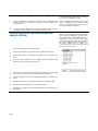
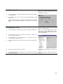
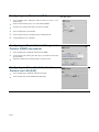
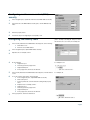
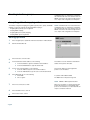
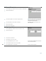
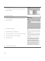
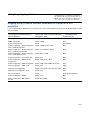
Configuring BayStack and Business Policy Switches
with the Preside Network Configuration System
This card summarizes how to get started using the Preside Network Configuration System (Preside NCS) to configure the
BayStack and Business Policy Switches (BPS) in your network. This document is intended for network engineers who have
some familiarity with Nortel Networks Layer 2 switches.
The Business Policy Switch 2000 requires version 1.1 software. The BayStack 350, 410, and 450 switches require versions
1.3–3.1 software.
Task list
The following summarizes an example of the configuration tasks you can complete using Preside NCS:
•
•
•
•
•
•
•
•
•
•
“Configuring the switch IP address”
“Importing or creating a switch configuration”
“Adding stack units and media dependent adapters (MDAs)“
“Configuring ports”
“Configuring VLANs”
“Configuring a multilink trunk (MLT)”
“Configuring an Simple Network Management Protocol (SNMP) trap receiver”
“Configuring an Extensible Authentication Protocol over LAN (EAP)”
“Configuring media access control (MAC) security”
Configuring QoS parameters:
— “Creating interface groups”
— “Accepting default mapping values”
— “Setting up filters“
— “Configuring actions“
— “Configuring meters“
— “Configuring policies”
— “Assigning mapping values”
If you are familiar with the BayStack Console Interface (CI), see the “Mapping Switch Console Interface commands to Preside NCS GUI
properties” table to locate the Preside NCS properties that you want to configure.
Each of the above tasks is explained in more detail in the procedures that follow.
Configuring the switch IP address
1
Connect a serial console and apply power to the switch. After the Nortel
Networks logo screen appears, press [Ctrl]-Y to access the Console Interface
(CI).
2
At the CI Main Menu, choose IP Configuration/Setup.
3
Type the in-band IP address or stack IP address, subnet mask, and default
gateway of the switch.
Press [Return] after each entry.
NOTE: If you have a properly configured BootP
server in your network, it detects the switch IP
address automatically; you do not need to
configure the IP address.
For a standalone switch, you enter the in-band IP
address. For a stack configuration, you enter the
stack IP address.
Page 1
Importing or creating a switch configuration
You can import existing configurations to the
Preside NCS database directly from the switch, or
you can create configurations off-line.
1
Use the Configuration menu Import commands to import configuration data
directly from a switch. To import data, you specify the switch IP address and
community string.
NOTE: BayStack and Business Policy Switch
devices use SNMP to transfer configuration data;
they do not support Trivial File Transfer Protocol
(TFTP) or serial import and export.
2
Use the Configuration Data Palette to create new standalone switch and stack
configurations. The Palette lists switch templates by product group.
Adding stack units and media dependent
adapters (MDAs)
NOTE: You can add switch units to a stack and
MDAs to a unit configuration using Preside NCS.
Then, export that configuration to a stack or unit to
which you added the corresponding hardware.
Alternatively, you can install the new unit or MDA
in the stack or unit and re-import the configuration
through Preside NCS. Re-import will then discover
the newly installed unit or MDA. It is
recommended that you follow this latter method
because it is less error-prone.
1
In the navigation pane, select the switch stack.
2
Select the unit type that is to be added to the stack from the Palette tab.
3
Click the Paste button, or double-click the unit type that is to be added to the
stack.
4
Select the newly created unit in the navigation pane and adjust the unit
number in the Basic tab in the Properties area.
5
Select the newly created unit in the navigation pane and then select the MDA
type that is to be added to the new switch unit from the Palette tab.
6
Click the Paste button or double-click the MDA type that is to be added to the
switch.
7
Expand the added unit in the navigation pane and then expand the MDA.
8
Select a port under the MDA object in the navigation pane.
9
Configure Basic, VLAN, STP, and IGMP parameters in the Properties tab as
appropriate.
Click Task list to return to the list of tasks.
Page 2
Configuring ports
1
In the navigation pane, expand the standalone switch, stack unit, or MDA to
select switch ports.
2
In the Properties tab, choose the Basic, VLAN, STP, IGMP, EAP, or MAC
Security tab.
By default, all unconfigured ports are untagged
links in the default port-based VLAN (VLAN 1),
participate in normal learning STP, and
autonegotiate line speed.
NOTE: Selecting multiple ports (Ctrl-Click or Shift-Click) and then modifying
parameters from the Properties tab changes those parameters for all selected
ports.
Configuring VLANs
You can configure port-based, protocol-based, or
MAC source address VLANs.
1
In the navigation pane, expand the device and select the device VLANs folder.
NOTE: Use the device VLANs folder to create
VLANs and to configure VLAN ports. The system
VLANs folder shows the VLANs configured on all
devices in the database.
2
In the Palette tab, choose a port-based, protocol-based, or MAC source
address (SA)-based VLAN type.
3
In the navigation pane, select the VLAN. In the Properties tab, type a
descriptive name to identify the VLAN.
4
In the navigation pane, expand the switch and select ports to participate in the
VLAN.
5
Create shortcuts from the ports to the VLAN.
Copy the ports, and paste them as shortcuts on
the VLAN.
6
In the navigation pane, select the VLAN ports. In the Properties tab, configure
the VLAN port properties.
Click the VLAN tab to display the VLAN port
properties.
Click Task list to return to the list of tasks.
Page 3
Configuring a multilink trunk (MLT)
1
In the navigation pane, expand the switch and select two, three, or four
Ethernet ports.
2
Create shortcuts from the ports to one of the six MLT templates.
3
Copy the ports, and then paste them as shortcuts on the MLT.
4
In the navigation pane, select the MLT.
5
In the Properties tab, type a descriptive name to identify the trunk.
6
From the Status list, choose Enabled.
Configuring an Simple Network Management
Protocol (SNMP) trap receiver
1
In the navigation pane, expand the switch and select SNMP.
2
In the Properties tab, click the green plus sign (+) to add an item to the Trap
Receivers table.
3
Enter the IP address and community string for each trap receiver.
Configuring an Extensible Authentication
Protocol over LAN (EAP)
1
In the navigation pane, expand the switch and select EAP.
2
In the Properties tab, click the Administrative State Value.
Click Task list to return to the list of tasks.
Page 4
You can configure from one through six multilink
trunk (MLT) groups.
Configuring media access control (MAC)
security
1
In the navigation pane, expand the switch and select MAC Address Security.
2
In the Basic tab of the MAC Address Security pane, click the MAC Security
Value.
3
Enter the property values.
4
Perform the steps in “Configuring the security table,” next.
Configuring the security table
NOTE: You manually assign ports
(Port 1...Port 24) to an entry (S1...S32). You enter
the allowed source as an entry. For example, S1.
1
In the Security Table tab of the MAC Address Security pane, do the following:
a. Click Add row icon.
b. Enter the source MAC address.
2
In the navigational pane, expand MAC Address Security.
3
Expand a unit, for example, Unit #1.
4
Do the following:
a. Right click a port.
b. Select Copy from the popup menu.
c. Right click Entry: S1.
d. In the popup menu, click Paste As Shortcut.
For example Port 1.
5
In the Security Table tab of the MAC Address Security pane, enter the allowed
source.
For example, S1.
6
To use the Learn by Port feature, do the following:
a. In the navigational pane, expand MAC Address Security.
b. Click Learn by Port.
c. In the Properties tab, select the Current Learning Mode property
value.
d. Expand a unit, for example, Unit #1.
e. Right click a port.
f.
Select Copy from the popup menu.
g. Right click Entry: S1.
h. In the popup menu, click Paste As Shortcut.
7
In the popup menu, click Paste As Shortcut.
Click Task list to return to the list of tasks.
Page 5
Creating interface groups
NOTE: Nortel Networks does not allow this action
from NCS, because to complete the configuration,
the switch must be reset. If the switch is reset, the
SNMP connection to the switch is dropped. In this
case, export of the configurations is interrupted.
Accepting default mapping values
To manually configure the mapping among 802.1p priority values, priority, and DSCP
mapping, you must use with the following QoS Advanced pages:
• Assigning 802.1p priority queue assignment
• Verifying DSCP mapping
• Assigning 802.1p user priority mapping
• Verifying DSCP queue assignments
NOTE: Nortel Networks does not allow this action
from NCS, because to complete the configuration,
the switch must be reset. If the switch is reset, the
SNMP connection to the switch is dropped. In this
case, export of the configurations is interrupted.
Setting up filters
1
In the navigation pane, expand the switch and select QoS > IP Classification.
2
Click the IP Table Filter tab.
3
In the Indices box, enter the value.
4
For the destination network address, do the following:
a. In the Dest Addr box, type the destination network address.
b. In the Dest Addr Mask box, type the subnet mask.
This address is used to match the destination IP
address in the packet’s IP header.
5
For the source network address, do the following:
a. In the Src Addr box, type the source network address.
b. In the Src Addr Mask box, type the source network subnet mask.
This is the IP address to match against the
packet’s source IP address.
6
In the DSCP field, do one of the following:
a. Enter 0x20.
b. Choose Ignore.
For packets with a DSCP of 0x20.
The DSCP value in the packet is ignored.
NOTE: A DSCP of 0x20 equals 32 decimal.
7
In the Protocol field, choose TCP.
8
In the Destination L4 box, enter 0.
9
In the Source L4 box, enter 0.
Click Task list to return to the list of tasks.
Page 6
When you select TCP, you specify that only TCP
packets be matched. If you select RSVP, all IP
protocols are matched. If you select Match All, all
IP protocols listed are matched.
Setting up filter groups
1
In the navigation pane, expand the switch and select QoS > IP Classification.
2
Click the IP Table Filter tab.
3
In the Filter Group ID box, enter a label, for example, IPacket.
NOTE: Do not leave spaces in your naming entry.
This unique identification label distinguishes this
filter group from other filter groups.
4
In the Filter Order box, enter a number, for example, 1.
5
Define the Layer 2 filter.
6
Define the Layer 2 filter group.
This number establishes the evaluation order of
filters in the group.
Configuring actions
1
In the navigation pane, expand the switch and select QoS > Actions.
2
Click the Properties tab.
3
In the Index box, enter Generic.
4
In the Drop box, choose True or False.
5
In the Update DSCP field, enter 47,0x2F.
6
In the Set Drop Precedence box, select Use Defaults.
7
In the Update Priority box, select Priority 1.
This entry changes the DSCP value to the decimal
value 47 in the match packet.
Priority 1 specifies a low priority.
Click Task list to return to the list of tasks.
Page 7
Configuring meters
1
In the navigation pane, expand the switch and select QoS > Meter Table.
2
Click the Properties tab.
3
Enter the properties values.
Configuring policies
1
In the navigation pane, expand the switch and select QoS > Policy Table.
2
Click the Properties tab.
3
In the Index box, enter IPpolicy.
NOTE: You cannot have spaces in the naming
field.
This entry is a unique name to identify this target.
4
In the Filter Group ID box, enter IP Filter Group.
This entry is the filter group that will be associated
with this policy.
5
In the Filter Group Type box, select an entry, for example, choose IPacket.
This entry is the filter group you created in the IP
Classification Group page, IP Filter Group Table.
6
In the Role Combination box, select a roll combination.
This entry is the unique Role Combination that
you created.
7
In the Order box, enter 1.
NOTE: Nortel Networks recommends that you
consider an order numbering strategy (for the
values in the Order field) as you configure
policies. The policies in the Policy Table are
arranged in ascending order according to value in
the Order column. By establishing a policy
ordering scheme in multiples of, for example, 10
(Order 10, Order 20, Order 30, Order 40, and so
on), you are able to insert policies in the
appropriate filter precedence location and still
retain the precedence of the remaining policies.
8
In the Action Index box, enter a value.
Click Task list to return to the list of tasks.
Page 8
Assigning mapping values
NOTE: Nortel Networks does not allow this action
from NCS, because to complete the configuration,
the switch must be reset. If the switch is reset, the
SNMP connection to the switch is dropped. In this
case, export of the configurations is interrupted.
Mapping Switch Console Interface commands to Preside NCS GUI
properties
If you are familiar with the BayStack Console Interface (CI), use the following table to locate the Preside NCS properties that you
want to configure.
To configure the properties on
this CI Screen...
Select this item in the Preside NCS ... and choose this
navigation pane...
Properties tab
IP Configuration/Setup
Switch
Basic
SNMP Configuration
Switch > SNMP
Basic
System Characteristics
Switch
Import/Export
Switch Configuration > VLAN Configuration
menu > VLAN Configuration
Switch > VLANs folder > VLAN
Basic
Switch Configuration > VLAN Configuration
menu > VLAN Port Configuration
Switch > port member of VLAN
VLAN
Switch Configuration > VLAN Configuration
menu > VLAN Display by Port
VLANs folder > VLAN
Basic
Switch Configuration > Port Configuration
Switch > port
Basic
Switch Configuration > Multilink Trunk
Configuration
Switch > MLT groups > MLT
Basic
Switch Configuration > IGMP Configuration
VLAN > IGMP tab and IGMP tab on ports
Basic
Switch Configuration > IGMP > port
Switch > port
IGMP
Spanning Tree Configuration
Switch > STG Group > Spanning Tree group
Basic
Spanning Tree Configuration > port
Switch > port
STG
Software Download
Switch
Image Download Wizard
Switch Configuration > EAPOL
Switch > Port
EAP
Switch Configuration > MAC Address
Security
Switch MAC Security
Basic
Click Task list to return to the list of tasks.
Page 9
*312061-B*
Copyright © November 2001 Nortel Networks. All rights reserved. Printed in the USA.
The information in this document is subject to change without notice. The statements, configurations, technical data, and recommendations in this document are
believed to be accurate and reliable, but are presented without express or implied warranty. Users must take full responsibility for their applications of any products
specified in this document. The information in this document is proprietary to Nortel Networks NA Inc.