1
Troubleshooting Guide
Avaya Business Communications Manager
Document Status: Standard
Document Number: NN40170-700
Document Version: 02.02
Date: June 2010
© 2010 Avaya Inc.
All Rights Reserved.
Notices
While reasonable efforts have been made to ensure that the information in this document is complete and accurate at the time of printing,
Avaya assumes no liability for any errors. Avaya reserves the right to make changes and corrections to the information in this document
without the obligation to notify any person or organization of such changes.
Documentation disclaimer
Avaya shall not be responsible for any modifications, additions, or deletions to the original published version of this documentation
unless such modifications, additions, or deletions were performed by Avaya. End User agree to indemnify and hold harmless Avaya,
Avaya’s agents, servants and employees against all claims, lawsuits, demands and judgments arising out of, or in connection with,
subsequent modifications, additions or deletions to this documentation, to the extent made by End User.
Link disclaimer
Avaya is not responsible for the contents or reliability of any linked Web sites referenced within this site or documentation(s) provided by
Avaya. Avaya is not responsible for the accuracy of any information, statement or content provided on these sites and does not
necessarily endorse the products, services, or information described or offered within them. Avaya does not guarantee that these links will
work all the time and has no control over the availability of the linked pages.
Warranty
Avaya provides a limited warranty on this product. Refer to your sales agreement to establish the terms of the limited warranty. In
addition, Avaya’s standard warranty language, as well as information regarding support for this product, while under warranty, is
available to Avaya customers and other parties through the Avaya Support Web site: http://www.avaya.com/support
Please note that if you acquired the product from an authorized reseller, the warranty is provided to you by said reseller and not by Avaya.
Licenses
THE SOFTWARE LICENSE TERMS AVAILABLE ON THE AVAYA WEBSITE, HTTP://SUPPORT.AVAYA.COM/LICENSEINFO/
ARE APPLICABLE TO ANYONE WHO DOWNLOADS, USES AND/OR INSTALLS AVAYA SOFTWARE, PURCHASED FROM
AVAYA INC., ANY AVAYA AFFILIATE, OR AN AUTHORIZED AVAYA RESELLER (AS APPLICABLE) UNDER A
COMMERCIAL AGREEMENT WITH AVAYA OR AN AUTHORIZED AVAYA RESELLER. UNLESS OTHERWISE AGREED TO
BY AVAYA IN WRITING, AVAYA DOES NOT EXTEND THIS LICENSE IF THE SOFTWARE WAS OBTAINED FROM ANYONE
OTHER THAN AVAYA, AN AVAYA AFFILIATE OR AN AVAYA AUTHORIZED RESELLER, AND AVAYA RESERVES THE
RIGHT TO TAKE LEGAL ACTION AGAINST YOU AND ANYONE ELSE USING OR SELLING THE SOFTWARE WITHOUT A
LICENSE. BY INSTALLING, DOWNLOADING OR USING THE SOFTWARE, OR AUTHORIZING OTHERS TO DO SO, YOU,
ON BEHALF OF YOURSELF AND THE ENTITY FOR WHOM YOU ARE INSTALLING, DOWNLOADING OR USING THE
SOFTWARE (HEREINAFTER REFERRED TO INTERCHANGEABLY AS "YOU" AND "END USER"), AGREE TO THESE
TERMS AND CONDITIONS AND CREATE A BINDING CONTRACT BETWEEN YOU AND AVAYA INC. OR THE
APPLICABLE AVAYA AFFILIATE ("AVAYA").
Copyright
Except where expressly stated otherwise, no use should be made of the Documentation(s) and Product(s) provided by Avaya. All content
in this documentation(s) and the product(s) provided by Avaya including the selection, arrangement and design of the content is owned
either by Avaya or its licensors and is protected by copyright and other intellectual property laws including the sui generis rights relating
to the protection of databases. You may not modify, copy, reproduce, republish, upload, post, transmit or distribute in any way any
content, in whole or in part, including any code and software. Unauthorized reproduction, transmission, dissemination, storage, and or
use without the express written consent of Avaya can be a criminal, as well as a civil offense under the applicable law.
Third Party Components
Certain software programs or portions thereof included in the Product may contain software distributed under third party agreements
("Third Party Components"), which may contain terms that expand or limit rights to use certain portions of the Product ("Third Party
Terms"). Information regarding distributed Linux OS source code (for those Products that have distributed the Linux OS source code),
and identifying the copyright holders of the Third Party Components and the Third Party Terms that apply to them is available on the
Avaya Support Web site: http://support.avaya.com/Copyright.
Trademarks
The trademarks, logos and service marks ("Marks") displayed in this site, the documentation(s) and product(s) provided by Avaya are the
registered or unregistered Marks of Avaya, its affiliates, or other third parties. Users are not permitted to use such Marks without prior
written consent from Avaya or such third party which may own the Mark. Nothing contained in this site, the documentation(s) and
product(s) should be construed as granting, by implication, estoppel, or otherwise, any license or right in and to the Marks without the
express written permission of Avaya or the applicable third party. Avaya is a registered trademark of Avaya Inc. All non-Avaya
trademarks are the property of their respective owners.
Downloading documents
For the most current versions of documentation, see the Avaya Support. Web site: http://www.avaya.com/support
Contact Avaya Support
Avaya provides a telephone number for you to use to report problems or to ask questions about your product. The support telephone
number is 1-800-242-2121 in the United States. For additional support telephone numbers, see the Avaya Web site: http://
www.avaya.com/support
Contents
3
Contents
Chapter 1
New in this release. . . . . . . . . . . . . . . . . . . . . . . . . . . . . . . . . . . . . . . . . . . . . . 7
Features . . . . . . . . . . . . . . . . . . . . . . . . . . . . . . . . . . . . . . . . . . . . . . . . . . . . . . . . . . . . 7
Chapter 2
Introduction . . . . . . . . . . . . . . . . . . . . . . . . . . . . . . . . . . . . . . . . . . . . . . . . . . . 9
Purpose . . . . . . . . . . . . . . . . . . . . . . . . . . . . . . . . . . . . . . . . . . . . . . . . . . . . . . . . . . . . . 9
Audience . . . . . . . . . . . . . . . . . . . . . . . . . . . . . . . . . . . . . . . . . . . . . . . . . . . . . . . . . . . . 9
Organization . . . . . . . . . . . . . . . . . . . . . . . . . . . . . . . . . . . . . . . . . . . . . . . . . . . . . . . . . 9
Acronyms . . . . . . . . . . . . . . . . . . . . . . . . . . . . . . . . . . . . . . . . . . . . . . . . . . . . . . . . . . . 10
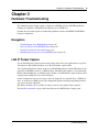
Symbols and conventions used in this guide . . . . . . . . . . . . . . . . . . . . . . . . . . . . . . . . 12
Chapter 3
Hardware Troubleshooting . . . . . . . . . . . . . . . . . . . . . . . . . . . . . . . . . . . . . . 15
Navigation . . . . . . . . . . . . . . . . . . . . . . . . . . . . . . . . . . . . . . . . . . . . . . . . . . . . . . . . . . 15
LAN IP Packet Capture . . . . . . . . . . . . . . . . . . . . . . . . . . . . . . . . . . . . . . . . . . . . . . . . 15
Troubleshooting Avaya BCM hardware . . . . . . . . . . . . . . . . . . . . . . . . . . . . . . . . . . . . 16
Check the power source . . . . . . . . . . . . . . . . . . . . . . . . . . . . . . . . . . . . . . . . . . . . 16
Check LED indicators . . . . . . . . . . . . . . . . . . . . . . . . . . . . . . . . . . . . . . . . . . . . . . 17
Avaya BCM450 system status LEDs . . . . . . . . . . . . . . . . . . . . . . . . . . . . . . . 17
Avaya BCM50 system status LEDs . . . . . . . . . . . . . . . . . . . . . . . . . . . . . . . . 17
LAN port LEDs . . . . . . . . . . . . . . . . . . . . . . . . . . . . . . . . . . . . . . . . . . . . . . . . 19
ADSL router LEDs (Avaya BCM50a and Avaya BCM50ba only) . . . . . . . . . . 21
Ethernet router LEDs (Avaya BCM50e and Avaya BCM50be only) . . . . . . . . 22
BRI port LEDs on main unit (BRI series only) . . . . . . . . . . . . . . . . . . . . . . . . . 23
Media bay module LEDs . . . . . . . . . . . . . . . . . . . . . . . . . . . . . . . . . . . . . . . . 24
DTM LEDs . . . . . . . . . . . . . . . . . . . . . . . . . . . . . . . . . . . . . . . . . . . . . . . . . . . 25
BRIM LEDs . . . . . . . . . . . . . . . . . . . . . . . . . . . . . . . . . . . . . . . . . . . . . . . . . . . 26
Check the wiring connections . . . . . . . . . . . . . . . . . . . . . . . . . . . . . . . . . . . . . . . . 26
Verify the keycodes . . . . . . . . . . . . . . . . . . . . . . . . . . . . . . . . . . . . . . . . . . . . . . . . 27
Restart or shut down the system . . . . . . . . . . . . . . . . . . . . . . . . . . . . . . . . . . . . . . 28
Reboot . . . . . . . . . . . . . . . . . . . . . . . . . . . . . . . . . . . . . . . . . . . . . . . . . . . . . . 29
Power on self test (Avaya BCM450 only) . . . . . . . . . . . . . . . . . . . . . . . . . . . . . . . . . . 30
Testing basic hardware functionality . . . . . . . . . . . . . . . . . . . . . . . . . . . . . . . . . . . . . . 31
Reset to factory settings . . . . . . . . . . . . . . . . . . . . . . . . . . . . . . . . . . . . . . . . . . . . . . . 36
Reset levels . . . . . . . . . . . . . . . . . . . . . . . . . . . . . . . . . . . . . . . . . . . . . . . . . . 38
Command Line Interface . . . . . . . . . . . . . . . . . . . . . . . . . . . . . . . . . . . . . . . . . . . . 38
Configuration CLI . . . . . . . . . . . . . . . . . . . . . . . . . . . . . . . . . . . . . . . . . . . . . . 38
Maintenance CLI . . . . . . . . . . . . . . . . . . . . . . . . . . . . . . . . . . . . . . . . . . . . . . 39
Troubleshooting Guide
4
Contents
Monitoring the boot process (Avaya BCM450 only) . . . . . . . . . . . . . . . . . . . . . . . . . . 40
Chapter 4
Initial Troubleshooting . . . . . . . . . . . . . . . . . . . . . . . . . . . . . . . . . . . . . . . . . 43
Navigation . . . . . . . . . . . . . . . . . . . . . . . . . . . . . . . . . . . . . . . . . . . . . . . . . . . . . . . . . . 43
Proper installation and routine maintenance . . . . . . . . . . . . . . . . . . . . . . . . . . . . . . . . 43
Network configuration . . . . . . . . . . . . . . . . . . . . . . . . . . . . . . . . . . . . . . . . . . . . . . . . . 43
Site network map . . . . . . . . . . . . . . . . . . . . . . . . . . . . . . . . . . . . . . . . . . . . . . . . . 43
Logical connections . . . . . . . . . . . . . . . . . . . . . . . . . . . . . . . . . . . . . . . . . . . . . . . . 44
Device configuration information . . . . . . . . . . . . . . . . . . . . . . . . . . . . . . . . . . . . . . 44
Other important data about your network . . . . . . . . . . . . . . . . . . . . . . . . . . . . . . . 44
Normal behavior on your network . . . . . . . . . . . . . . . . . . . . . . . . . . . . . . . . . . . . . . . . 44
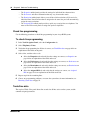
Chapter 5
Software Troubleshooting. . . . . . . . . . . . . . . . . . . . . . . . . . . . . . . . . . . . . . . 45
Navigation . . . . . . . . . . . . . . . . . . . . . . . . . . . . . . . . . . . . . . . . . . . . . . . . . . . . . . . . . . 45
Verify the software version . . . . . . . . . . . . . . . . . . . . . . . . . . . . . . . . . . . . . . . . . . . . . 45
Verify the keycodes . . . . . . . . . . . . . . . . . . . . . . . . . . . . . . . . . . . . . . . . . . . . . . . . . . . 45
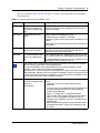
Check the programming of lines and phones . . . . . . . . . . . . . . . . . . . . . . . . . . . . . . . 45
Check line programming . . . . . . . . . . . . . . . . . . . . . . . . . . . . . . . . . . . . . . . . . . . . 46
Trunk/Line data . . . . . . . . . . . . . . . . . . . . . . . . . . . . . . . . . . . . . . . . . . . . . . . . . . . 46
Properties . . . . . . . . . . . . . . . . . . . . . . . . . . . . . . . . . . . . . . . . . . . . . . . . . . . . . . . 48
Preferences . . . . . . . . . . . . . . . . . . . . . . . . . . . . . . . . . . . . . . . . . . . . . . . . . . . . . . 49
Restrictions . . . . . . . . . . . . . . . . . . . . . . . . . . . . . . . . . . . . . . . . . . . . . . . . . . . . . . 52
Assigned DNs . . . . . . . . . . . . . . . . . . . . . . . . . . . . . . . . . . . . . . . . . . . . . . . . . . . . 53
Restoring system data . . . . . . . . . . . . . . . . . . . . . . . . . . . . . . . . . . . . . . . . . . . . . . . . . 54
Restoring data from an archive . . . . . . . . . . . . . . . . . . . . . . . . . . . . . . . . . . . 54
Restoring the factory configuration . . . . . . . . . . . . . . . . . . . . . . . . . . . . . . . . . 55
Verify the software inventory . . . . . . . . . . . . . . . . . . . . . . . . . . . . . . . . . . . . . . . . . . . . 55
Viewing the inventory of Avaya BCM software . . . . . . . . . . . . . . . . . . . . . . . . . . . 55
Obtaining software updates . . . . . . . . . . . . . . . . . . . . . . . . . . . . . . . . . . . . . . . . . 56
Chapter 6
Advanced Troubleshooting. . . . . . . . . . . . . . . . . . . . . . . . . . . . . . . . . . . . . . 57
Navigation . . . . . . . . . . . . . . . . . . . . . . . . . . . . . . . . . . . . . . . . . . . . . . . . . . . . . . . . . . 57
Example 1: Cannot dial out from an analog trunk . . . . . . . . . . . . . . . . . . . . . . . . . . . . 57
Example 2: Cannot dial out from a SIP or H323 VoIP trunk . . . . . . . . . . . . . . . . . . . . 62
Example 3: IP set is not registering with the Avaya BCM . . . . . . . . . . . . . . . . . . . . . . 68
Example 4: Cannot install keycode or invalid keycode application . . . . . . . . . . . . . . . 70
Example 5: Cannot dial out from digital trunk . . . . . . . . . . . . . . . . . . . . . . . . . . . . . . . 70
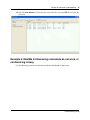
Example 6: MeetMe Conferencing commands do not work, or conferencing is busy . 75
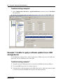
Example 7: Unable to apply a software update from a USB storage device . . . . . . . . 76
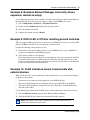
Example 8: Business Element Manager incorrectly shows expansion cabinet as empty 77
NN40170-700
Contents
5
Example 9: HDD-2 LED is Off after installing second hard disk . . . . . . . . . . . . . . . . . 77
Example 10: VLAN interfaces cannot communicate with external devices . . . . . . . . . 77
Chapter 7
Recovery trees . . . . . . . . . . . . . . . . . . . . . . . . . . . . . . . . . . . . . . . . . . . . . . . . 79
Navigation . . . . . . . . . . . . . . . . . . . . . . . . . . . . . . . . . . . . . . . . . . . . . . . . . . . . . . . . . . 79
System is not processing calls . . . . . . . . . . . . . . . . . . . . . . . . . . . . . . . . . . . . . . . . . . 79
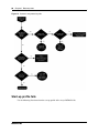
Start-up profile fails . . . . . . . . . . . . . . . . . . . . . . . . . . . . . . . . . . . . . . . . . . . . . . . . . . . 80
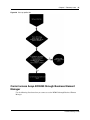
Cannot access Avaya BCM450 through Business Element Manager . . . . . . . . . . . . . 81
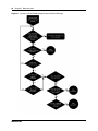
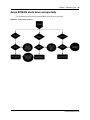
Avaya BCM450 shuts down unexpectedly . . . . . . . . . . . . . . . . . . . . . . . . . . . . . . . . . 83
Chapter 8
Downloading Software . . . . . . . . . . . . . . . . . . . . . . . . . . . . . . . . . . . . . . . . . 85
Navigation . . . . . . . . . . . . . . . . . . . . . . . . . . . . . . . . . . . . . . . . . . . . . . . . . . . . . . . . . . 85
Downloading software from the Avaya BCM system webpage . . . . . . . . . . . . . . . . . . 85
Downloading software from the Avaya web site . . . . . . . . . . . . . . . . . . . . . . . . . . . . . 88
Chapter 9
Troubleshooting Tools . . . . . . . . . . . . . . . . . . . . . . . . . . . . . . . . . . . . . . . . . 89
Navigation . . . . . . . . . . . . . . . . . . . . . . . . . . . . . . . . . . . . . . . . . . . . . . . . . . . . . . . . . . 89
Service Management . . . . . . . . . . . . . . . . . . . . . . . . . . . . . . . . . . . . . . . . . . . . . . . . . . 89
Status and Metrics . . . . . . . . . . . . . . . . . . . . . . . . . . . . . . . . . . . . . . . . . . . . . . . . . . . . 89
Utilities . . . . . . . . . . . . . . . . . . . . . . . . . . . . . . . . . . . . . . . . . . . . . . . . . . . . . . . . . . . . . 90
Command Line Interface . . . . . . . . . . . . . . . . . . . . . . . . . . . . . . . . . . . . . . . . . . . . . . . 90
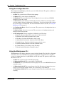
Accessing the CLI . . . . . . . . . . . . . . . . . . . . . . . . . . . . . . . . . . . . . . . . . . . . . . . . . 91
Using the Configuration CLI . . . . . . . . . . . . . . . . . . . . . . . . . . . . . . . . . . . . . . . . . 92
Using the Maintenance CLI . . . . . . . . . . . . . . . . . . . . . . . . . . . . . . . . . . . . . . . . . . 92
Chapter 10
Understanding System Messages . . . . . . . . . . . . . . . . . . . . . . . . . . . . . . . . 95
Alarms, logs, and traps . . . . . . . . . . . . . . . . . . . . . . . . . . . . . . . . . . . . . . . . . . . . . . . . 95
Reporting for dropped calls . . . . . . . . . . . . . . . . . . . . . . . . . . . . . . . . . . . . . . . . . . . . . 95
Chapter 11
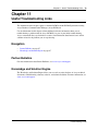
Useful Troubleshooting Links . . . . . . . . . . . . . . . . . . . . . . . . . . . . . . . . . . . 97
Navigation . . . . . . . . . . . . . . . . . . . . . . . . . . . . . . . . . . . . . . . . . . . . . . . . . . . . . . . . . . 97
Partner Bulletins . . . . . . . . . . . . . . . . . . . . . . . . . . . . . . . . . . . . . . . . . . . . . . . . . . . . . 97
Knowledge and Solution Engine . . . . . . . . . . . . . . . . . . . . . . . . . . . . . . . . . . . . . . . . . 97
Chapter 12
Frequently Asked Questions . . . . . . . . . . . . . . . . . . . . . . . . . . . . . . . . . . . . 99
Navigation . . . . . . . . . . . . . . . . . . . . . . . . . . . . . . . . . . . . . . . . . . . . . . . . . . . . . . . . . . 99
Backup, restore, and reset operations . . . . . . . . . . . . . . . . . . . . . . . . . . . . . . . . . . . . . 99
Troubleshooting Guide
6
Contents
How do I back up the database? . . . . . . . . . . . . . . . . . . . . . . . . . . . . . . . . . . . . . . 99
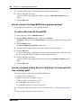
How do I restore the Avaya BCM from a previous backup? . . . . . . . . . . . . . . . . 100
How do I complete a Warm Reset or Cold Reset? Is it safe and will I lose customer data? 100
Password protection . . . . . . . . . . . . . . . . . . . . . . . . . . . . . . . . . . . . . . . . . . . . . . . . . 101
How do I recover a lost password for the Avaya BCM? . . . . . . . . . . . . . . . . . . . 101
Fault management . . . . . . . . . . . . . . . . . . . . . . . . . . . . . . . . . . . . . . . . . . . . . . . . . . . 102
How do I view Alarms? Can I acknowledge and clear them? . . . . . . . . . . . . . . . 102
System and status information . . . . . . . . . . . . . . . . . . . . . . . . . . . . . . . . . . . . . . . . . 103
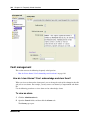
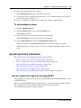
How do I capture the logs from the Avaya BCM? . . . . . . . . . . . . . . . . . . . . . . . . 103
Using the Avaya BCM Web Page to transfer log files . . . . . . . . . . . . . . . . . 104
How do I capture the current Avaya BCM configuration? . . . . . . . . . . . . . . . . . . 105
How do I find the Avaya BCM system health? . . . . . . . . . . . . . . . . . . . . . . . . . . 106
How do I show specific process states? . . . . . . . . . . . . . . . . . . . . . . . . . . . . . . . 106
How do I verify current software revision? . . . . . . . . . . . . . . . . . . . . . . . . . . . . . 106
How do I find the Avaya BCM450 System ID and Serial Number? . . . . . . . . . . . 107
Connectivity problems . . . . . . . . . . . . . . . . . . . . . . . . . . . . . . . . . . . . . . . . . . . . . . . . 108
What is an Ethernet loop, and how do I avoid creating one? . . . . . . . . . . . . . . . 108
IP addresses . . . . . . . . . . . . . . . . . . . . . . . . . . . . . . . . . . . . . . . . . . . . . . . . . . . . . . . 109
Can I modify the IP address of the OAM port? . . . . . . . . . . . . . . . . . . . . . . . . . . 109
What are the default IP addresses of the Avaya BCM ports? . . . . . . . . . . . . . . . 110
Chapter 13
Contacting Technical Support . . . . . . . . . . . . . . . . . . . . . . . . . . . . . . . . . . 111
Navigation . . . . . . . . . . . . . . . . . . . . . . . . . . . . . . . . . . . . . . . . . . . . . . . . . . . . . . . . . 111
Getting technical documentation . . . . . . . . . . . . . . . . . . . . . . . . . . . . . . . . . . . . . . . . 111
Getting product training . . . . . . . . . . . . . . . . . . . . . . . . . . . . . . . . . . . . . . . . . . . . . . . 111
Getting help from a distributor or reseller . . . . . . . . . . . . . . . . . . . . . . . . . . . . . . . . . 111
Getting technical support from the Avaya Web site . . . . . . . . . . . . . . . . . . . . . . . . . . 111
NN40170-700
Chapter 1 New in this release
7
Chapter 1
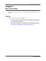
New in this release
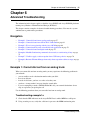
The following section details what’s new in Avaya Business Communications Manager (Avaya
BCM) 6.0.
Features
The following features are new for Avaya BCM 6.0:
•
•
Analog Trunk support for Find Me/Follow Me using Voice Activity Detection (VAD).
For more information about troubleshooting VAD, see Example 1: Cannot dial out
from an analog trunk on page 57.
Avaya BCM 6.0 introduces the new Muti-Image Hard Drive Field Replaceable Unit
(FRU). For more information about new LED states related to Multi-Image Hard Drives,
see LED states with descriptions of LED combinations on page 18
Troubleshooting Guide
8
Chapter 1 New in this release
NN40020-600
NN40170-700
Chapter 2 Introduction
9
Chapter 2
Introduction
Avaya Business Communications Manager (Avaya BCM) 6.0 provides private network and
telephony management capability to small and medium-sized businesses. The Avaya BCM system
integrates voice and data capabilities, and IP Telephony gateway functions into a single telephony
system. It also enables you to create and provide telephony applications for use in a business
environment.
Purpose
This guide provides procedural information to help you troubleshoot and isolate problems in your
BCM network.
Audience
The Avaya Business Communications Manager 6.0 Troubleshooting Guide is for use by network
administrators responsible for maintaining Avaya BCM networks. This guide is also useful for
network operations center (NOC) personnel supporting a BCM managed services solution. The
following are the considerations to use this guide:
•
•
•
be an authorized BCM administrator within your organization
know basic Avaya BCM terminology
be knowledgeable about telephony and IP networking technology
Organization
This guide is organized for easy access to information that explains the troubleshooting procedures
associated with using the Avaya BCM system. This guide contains information on the following
topics:
•
•
•
•
•
•
•
•
•
•
Initial Troubleshooting on page 43
Hardware Troubleshooting on page 15
Software Troubleshooting on page 45
Advanced Troubleshooting on page 57
Recovery trees on page 79
Downloading Software on page 85
Troubleshooting Tools on page 89
Understanding System Messages on page 95
Useful Troubleshooting Links on page 97
Frequently Asked Questions on page 99
Troubleshooting Guide
10
Chapter 2 Introduction
•
Contacting Technical Support on page 111
Acronyms
The following is a list of acronyms used in this guide.
Table 1 List of acronyms
Acronym
Description
3DES
Triple Data Encryption Standard
AES
Analog Encryption Standard
AIS
Alarm Indication Signal
BCM
Avaya Business Communications Manager
BFT
Base Function Tray
BRI
Basic Rate Interface
CbC
Call by Call
CDR
Call Detail Recording
CFA
Carrier Failure Alarms
CIF
Chassis Interface Card
CLID
Calling Line Identification
CPE
Customer Premises Equipment
CSU
Channel Service Unit
DES
Digital Encryption Standard
DHCP
Dynamic Host Configuration Protocol
DN
Directory Number
DNS
Domain Name Server
DNIS
Dialed Number Identification Service
DTM
Digital Trunk Module
ES
Errored Seconds
HTTP
Hypertext Transfer Protocol
IP
Internet Protocol
ISDN
Integrated Switched Digital Network
LAN
Local Area Network
MBM
Media Bay Module
MIB
Management Information Base
MGS
Media Gateway Server
MOS
Mean Opinion Score
MPS
Media Path Server
NAT
Network Address Translation
NCM
Network Configuration Manager
NN40170-700
Chapter 2 Introduction
11
Table 1 List of acronyms
Acronym
Description
NOC
Network Operations Center
NTP
Network Time Protocol
OOF
Out of Frame
PPP
Point-to-Point Protocol
PRI
Primary Rate Interface
PBX
Private Branch Exchange
PSTN
Public Switched Telephone Network
PVQM
Proactive Voice Quality Monitoring
QoS
Quality of Service
RAI
Remote Alarm Indication
RTP
Real-time Transport Protocol
SFTP
Secure File Transfer Protocol
SNMP
Simple Network Management Protocol
SSH
Secure Shell
SSL
Secure Socket Layer
UAS
Unavailable Seconds
UPS
Uninterrruptable Power Supply
USB
Universal Serial Bus
VoIP
Voice over Internet Protocol
VLAN
Virtual Local Area Network
VPN
Virtual Private Network
WAN
Wide Area Network
Troubleshooting Guide
12
Chapter 2 Introduction
Symbols and conventions used in this guide
These symbols are used to highlight critical information for the Avaya BCM system:
Caution: Alerts you to conditions where you can damage the equipment.
Danger: Alerts you to conditions where you can get an electrical shock.
Warning: Alerts you to conditions where you can cause the system to fail or work
improperly.
Note: A Note alerts you to important information.
Tip: Alerts you to additional information that can help you perform a task.
!
Security note: Indicates a point of system security where a default should be changed,
or where the administrator needs to make a decision about the level of security required
for the system.
Warning: Alerts you to ground yourself with an antistatic grounding
strap before performing the maintenance procedure.
Warning: Alerts you to remove the Avaya BCM main unit and
expansion unit power cords from the ac outlet before performing any
maintenance procedure.
NN40170-700
Chapter 2 Introduction
13
Related publications are listed below. For more information, see Avaya Business Communications
Manager Documentation Roadmap (NN40170-119).
Avaya Business Communications Manager 6.0 Administration and Security (NN40170-603)
Avaya Business Communications Manager 450 6.0 Installation—System (NN40170-303)
Avaya Business Communications Manager 450 6.0 Maintenance (NN40170-503)
Avaya Business Communications Manager 450 6.0 Installation and Maintenance (NN40170-305)
Keycode Installation Guide (NN40010-301)
Avaya Business Communications Manager 6.0 Configuration—Devices (NN40170-500)
Avaya Business Communications Manager 6.0 Configuration—System (NN40170-501)
Telset Administration Guide (NN40070-604)
CallPilot Telephone Administration Guide (NN40170-601)
CallPilot Contact Center Telephone Administration Guide (NN40170-600)
Troubleshooting Guide
14
Chapter 2 Introduction
NN40170-700
Chapter 3 Hardware Troubleshooting
15
Chapter 3
Hardware Troubleshooting
The information in this chapter applies to both Avaya BCM50 and Avaya BCM450 platforms
running Avaya Business Communications Manager (Avaya BCM) 6.0.
Perform the tasks in this chapter to troubleshoot problems related to the BCM50 and BCM450
hardware components.
Navigation
•
•
•
•
Troubleshooting Avaya BCM hardware on page 16
Power on self test (Avaya BCM450 only) on page 30
Testing basic hardware functionality on page 31
Monitoring the boot process (Avaya BCM450 only) on page 40
LAN IP Packet Capture
Use the LAN IP packet capture feature to help isolate and resolve voice applications set up issues.
You must have DataAdmin privileges to use the LAN Packet capture feature.
You can initiate IP packets capture on the Avaya BCM LAN and store captured IP packets in the
output file on BCM filesystem or a USB flash drive. LAN IP Packet Capture is accessed through
Business Element Manager at Administration > Utilities > LAN IP Packet Capture. Packets can be
captured at the OAM port or any of the LAN ports.
On the Configuration tab, you can select to store the output file on a network drive, a USB flash
drive, or on the Avaya BCM system. The configuration options will change depending on where
you want to store the output file.
The Filters tab allows you to set filters to reduce or increase the amount of data captured.
The table Reset functions on page 16 lists the fields on the LAN IP Packet Capture panel.
Troubleshooting Guide
16
Chapter 3 Hardware Troubleshooting
Table 1 Reset functions
Variable
Description
Port
The port you want to capture from. If LAN is selected,
all LAN ports will be captured.
Mode
Promiscuous: gives IP Packet Capture access to all
packets on the LAN.
Non-promiscuous: gives IP Packet Capture access
only to packets coming to or from the BCM.
Output format
Allows you to select the output format. The options
are:
Raw: The raw packet data.
Text: converts the data to a text file.
Duration (sec) :
The duration (in seconds) of the capture.
Start
Starts the capture
Stop
Stops the capture
Status
View the status of the capture
IP packets going to WAN port will not be captured if entering one of the router ports regardless of
Promiscuous mode state. Any packets entering any of the LAN ports will always be captured if
promiscuous mode is ON.
If you are using a USB flash drive and it is disconnected during the capture, the capture session
does not stop. Stop the capture manually before disconnecting the USB drive.
Troubleshooting Avaya BCM hardware
Complete the following tasks, in the order shown below, to troubleshoot some of the common
problems that you may encounter with the Avaya BCM50 and Avaya BCM450 hardware:
•
•
•
•
•
Check the power source on page 16
Check LED indicators on page 17
Check the wiring connections on page 26
Verify the keycodes on page 27
Restart or shut down the system on page 28
Check the power source
Begin troubleshooting the hardware by checking the power source:
•
•
check the connection between the power supply and the main unit
check the connection from the power supply to the electrical outlet
NN40170-700
Chapter 3 Hardware Troubleshooting
17
Check LED indicators
After checking the power source, check the LED indicators. This section describes the operation of
the Avaya BCM450 system LEDs:
•
•
•
•
•
•
•
•
•
Avaya BCM450 system status LEDs on page 17
Avaya BCM50 system status LEDs on page 17
LAN port LEDs on page 19
ADSL router LEDs (Avaya BCM50a and Avaya BCM50ba only) on page 21
Ethernet router LEDs (Avaya BCM50e and Avaya BCM50be only) on page 22
BRI port LEDs on main unit (BRI series only) on page 23
Media bay module LEDs on page 24
DTM LEDs on page 25
BRIM LEDs on page 26
Not all MBMs are supported on all platforms. For more information about which MBMs are
supported on each platform, see Avaya Business Communications Manager 450 6.0 Installation—
System (NN40170-303), Avaya Business Communications Manager 450 6.0 Maintenance
(NN40170-503), or Avaya BCM50 6.0 Installation and Maintenance Guide (NN40170-305).
Avaya BCM450 system status LEDs
The chassis of the Avaya BCM450 contains two LEDs: a Status LED and a Power LED. The
Power LED is located at the bottom left of the chassis; the Status LED is immediately above it.
The LED states with descriptions of LED combinations table describes the meaning of the system
status LEDs in the following situations:
•
•
•
•
start-up sequence: LED indicators during the normal start-up process
safe-mode start-up sequence: LED indicators during a safe-mode start-up
shutdown sequence: LED indictors during a shutdown or failure
start-up profile sequence: LED indicators during an initial installation or staging
Avaya BCM50 system status LEDs
The information in this section applies to the Avaya BCM50 platform only.
The two system status LEDs on the BCM50 main units (BCM50, BCM50a, BCM50e, BCM50b,
BCM50ba, and BCM50be) show the current state of the Avaya BCM50 system.
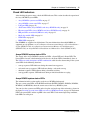
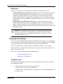
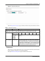
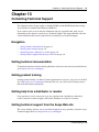
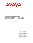
You can view the system status LEDs on the faceplate and on the top of the main unit, as shown in
the figure Location of system status LEDs on an Avaya BCM50 main unit on page 18. The bottom
LED is the power LED, and the top LED is the status LED. Under normal operating conditions,
both LEDs are solid green.
Troubleshooting Guide
18
Chapter 3 Hardware Troubleshooting
Figure 1 Location of system status LEDs on an Avaya BCM50 main unit
The LED states with descriptions of LED combinations table describes the meaning of the system
status LEDs after the system turn on and is in service.
During BCM50 system startup or restart, the system status LEDs move through a sequence of state
changes. If either the power LED or status LED is yellow, the system is initializing and is not
ready for service. The LED states with descriptions of LED combinations table shows the key
states indicating service availability.
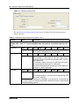
Table 2 LED states with descriptions of LED combinations
Power LED
Status LED
LED combinations description
Start-up sequence
Solid yellow
Solid yellow
Power is applied to the system.
Solid yellow
Off
POST (Power On Self Test) (duration 9 seconds)
Solid yellow
Solid yellow
System initialization (duration 14 seconds)
Solid green
Solid yellow
Kernel initialization (duration 8 seconds) or Safe OS
Solid green
Blink yellow
Waiting for user input on Multi-Image Hard Drive CLI
Solid red
Solid red
Installation is in progress (Multi-Image
Hard Drive)
Solid red
Blink red
Error during installation (Multi-Image
Hard Drive)
Solid green
Blinking green
Services initialization (duration 1 minute)
Solid green
Solid green
System running
Solid green
Solid red
Services initialization FAILURE
Safe Mode start-up sequence
Solid red
NN40170-700
Solid green
System is running with manufacturing settings enabled
Chapter 3 Hardware Troubleshooting
19
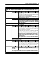
Table 2 LED states with descriptions of LED combinations
Power LED
Status LED
LED combinations description
Solid red
Solid red
System is running in Software Reset mode
Solid red
Blinking yellow
System is running in Configuration Reset mode
Shutdown sequence or FAILURE
Solid green
Blinking yellow
Graceful shutdown in progress (trigger: Business Element
Manager or UPS)
Off
Solid yellow
Graceful shutdown completed.
Solid red
Blinking yellow
Overheat detected; thermal shutdown completed
Solid red
Solid red
Power spike or rail power fluctuation detected
Blinking red
Solid red
Rail power fluctuation; power monitor shutdown completed
Solid yellow
Solid red
Power spike shutdown completed (temperature and rail
power OK)
Off
Off
No power; system is shut down (power cable is
disconnected)
Start-up profile (LED combinations seen only during initial system install or staging)
Blinking yellow
Blinking yellow
Start-up profile executing
Solid green
Solid green
Start-up profile successfully applied
Blinking yellow
Blinking red
Start-up profile FAILURE
LAN port LEDs
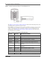
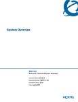
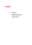
Each LAN port on the main unit and expansion unit has two LEDs. These LEDs indicate the status
of the connection for that LAN port. The LAN port LED locations on the Avaya BCM450 main
unit table shows the location of these LEDs on the main unit.
Troubleshooting Guide
20
Chapter 3 Hardware Troubleshooting
Figure 2 LAN port LED locations on the Avaya BCM450 main unit
LAN port LEDs
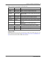
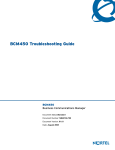
The figure LAN port LED locations on the Avaya BCM50 main unit on page 21 shows the LAN
port LED locations on the Avaya BCM50 main unit. The expansion ports on the BCM50 main unit
also function as LAN ports. The expansion port LEDs indicate LAN activity only. The LEDs do
not indicate expansion unit presence. The LEDs do not light.
NN40170-700
Chapter 3 Hardware Troubleshooting
21
Figure 3 LAN port LED locations on the Avaya BCM50 main unit
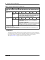
The LAN port and expansion port LED indicators table describes the possible LED states for the
LAN ports LEDs.
Table 3 LAN port and expansion port LED indicators
LED
Status
Yellow (left
LED)
On
Description
The LAN port is operating at 10 Mb/s.
Green (right
On
LED)
The LAN port is operating at 100 Mb/s.
Both LEDs
Off
No connection.
Any LED
Flashing
The LAN port is sending or receiving network data. The frequency of the flashes
increases with increased traffic.
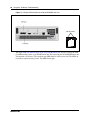
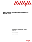
ADSL router LEDs (Avaya BCM50a and Avaya BCM50ba only)
The three ADSL router LEDs on the faceplate of the Avaya BCM50a and Avaya BCM50ba main
units monitor router status, data, and DSL. The figure ADSL router LEDs on the Avaya BCM50a
and Avaya BCM50ba main units (BCM50a shown) on page 22 shows the location of the three
ADSL router LEDs.
Troubleshooting Guide
22
Chapter 3 Hardware Troubleshooting
Figure 4 ADSL router LEDs on the Avaya BCM50a and Avaya BCM50ba main units (BCM50a shown)
The ADSL router LED descriptions table describes the possible ADSL router LED states.
Table 4 ADSL router LED descriptions
LED
Status
Description
Router status
On
The router card is functioning properly.
Off
The router card is not ready or has malfunctioned.
Flashing
The router card restarts.
Flashing
The router card is sending or receiving data through the
WAN port.
Off
The router card is not sending or receiving data through the
WAN port.
On
The router card is linked successfully to a digital subscriber
line access multiplexer (DSLAM).
Off
The DSL link is not functioning.
Flashing
The router card is initializing the DSL line.
Data
DSL
Ethernet router LEDs (Avaya BCM50e and Avaya BCM50be only)
The three Ethernet router LEDs on the BCM50e and BCM50be main units monitor the router
status and the WAN port. The figure Ethernet router LEDs on the Avaya BCM50e and Avaya
BCM50be main units (BCM50e shown) on page 23 shows the location of the three Ethernet router
LEDs.
NN40170-700
Chapter 3 Hardware Troubleshooting
23
Figure 5 Ethernet router LEDs on the Avaya BCM50e and Avaya BCM50be main units (BCM50e shown)
The LAN port LED indicators table describes the possible Ethernet router LED states.
Table 5 LAN port LED indicators
LED
Status
Description
Router status
On
The router card is functioning properly.
Off
The router card is not ready or malfunctioned.
Flashing
The router card restarts.
WAN port yellow
On
The WAN port is operating at 10 Mb/s.
WAN port green
On
The WAN port is operating at 100 Mb/s.
Any WAN port LED
Flashing
The WAN port is sending or receiving network data. The
frequency of the flashes increases with increased traffic.
Both WAN port LEDs
Off
No connection.
BRI port LEDs on main unit (BRI series only)
The three BRI port LEDs on the Avaya BCM50b, Avaya BCM50ba, and Avaya BCM50be main
units monitor the BRI port status. The figure BRI port LEDs on the BCM50b, BCM50ba, and
BCM50be main units (BCM50b shown) on page 24 shows the location of the BRI ports and LEDs.
Troubleshooting Guide
24
Chapter 3 Hardware Troubleshooting
Figure 6 BRI port LEDs on the BCM50b, BCM50ba, and BCM50be main units (BCM50b shown)
The BRI port LED indicators table describes the possible BRI port LED states.
Table 6 BRI port LED indicators
LED (channel)
Status
Description
D
On (green)
D channel is functioning through this BRI port.
B1
On (green)
B channel 1 is functioning through this BRI port.
B2
On (green)
B channel 2 is functioning through this BRI port.
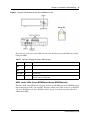
Media bay module LEDs
The two media bay module (MBM) LEDs on an expansion unit show the power and status of the
(Power) and Status LEDs
MBM. The figure MBM LEDs on page 24 shows the location of the
on an MBM. The power and status LEDs are in the same location on all MBMs.
Figure 7 MBM LEDs
Power
Status
The MBM LED descriptions table describes the possible MBM LED states.
Table 7 MBM LED descriptions
Power
Status
Description
Off
Off
The MBM has no power, or a failure occurred on the MBM power converter.
On
Off
Avaya BCM450 to expansion unit failure or system initialization.
NN40170-700
Chapter 3 Hardware Troubleshooting
25
Table 7 MBM LED descriptions
Power
Status
Description
On
Blinking
Hardware is working, but an operational problem exists such as:
• no link to the main unit is detected
• frame alignment is lost on messages from the main unit
• bandwidth not allocated
• MBM is in maintenance state
• MBM is in download state (GASM, GATM4/GATM8)
Blinking
Blinking
The MBM has power, but a hardware problem exists such as:
• partial failure of power converter
• thermal overload
• fan failure
On
On
The MBM is ready to operate.
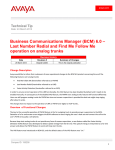
DTM LEDs
The DTM has additional LEDs that are not on most other MBMs. Figure 8 on page 25 shows the
location of the DTM LEDs.
Figure 8 DTM LEDs
Power LED
Status LED
In service LED
Loopback test LED
Receive LEDs
Error
Alarm
Transmit LEDs
Error
Alarm
The DTM LED functions table describes the functions of the DTM LEDs.
Table 8 DTM LED functions (Sheet 1 of 2)
LED
Status
Descriptions
Power
–
See “Media bay module LEDs” for details.
Status
–
See “Media bay module LEDs” for details.
In service
Flashing
The T1, ETSI, or PRI trunks are out of service because a loopback test is
running or the DTM is initializing.
Loopback test
On
A continuity loopback test is running.
Troubleshooting Guide
26
Chapter 3 Hardware Troubleshooting
Table 8 DTM LED functions (Sheet 2 of 2)
LED
Status
Descriptions
Receive alarm
On
A problem with the received digital transmission. This half-duplex link does
not work.
Receive error
On
A small error as a result of degraded digital transmission. Possible causes are
an ohmic connection, water ingress, or too long a loop.
Transmit alarm
On
The DTM cannot transmit. The DTM sends an alarm indication signal (AIS) to
the terminating switch. This half-duplex link does not work.
Transmit error
On
The DTM is sending a remote alarm indication (RAI) carrier failure alarm
(CFA) to the terminating switch. If the transmit alarm is not on, this error
indicates a far-end or cable problem.
All LEDS
Flashing
The DTM is initializing.
BRIM LEDs
The BRIM has one additional LED beside each RJ-48C jack. These LEDs are on when the ISDN
line is active. The figure BRIM LEDs on page 26 shows the location of the LEDs on a BRIM.
Figure 9 BRIM LEDs
Power LED
Status LED
For more information on the power and status LED functions, see Media bay module LEDs on
page 24.
Check the wiring connections
After you check the power source and the LEDs, begin to check the wiring. Check the connections
between the following components:
•
•
•
•
•
the expansion unit and the main unit
the main unit and to the MBMs—make sure that the cables are properly seated and are
connected to the correct ports
for the Avaya BCM450, the power supply and the AC power outlet
for the Avaya BCM50, the power supply and the main unit and the AC power outlet
if you are using a UPS, check the connection from:
— the USB port on the Avaya BCM450 to the USB port on the UPS
— the UPS and the electrical outlet
NN40170-700
Chapter 3 Hardware Troubleshooting
•
•
•
27
— the connection from the power supply to both the UPS and the BCM450 main unit
the lines and extensions connected through the RJ-21 telephony connector
the auxiliary equipment—connections at the auxiliary terminal block, or at the patch panel
For more information on wiring connections, refer to Avaya Business Communications
Manager 450 6.0 Installation—System (NN40170-303) or Avaya BCM50 6.0 Installation and
Maintenance (NN40170-305).
Verify the keycodes
If a specific feature is not functioning, verify that the feature is included in your installed
keycodes. This section provides procedure for verifying the installed keycodes using either
Business Element Manager or Telset. For more detailed information about retrieving and entering
the keycode for your system, see the Keycode Installation Guide (NN40010-301).
To verify the keycodes using Business Element Manager
1
In the Task Navigation Panel, select the Configuration tab.
2
Select the System folder and click the Keycodes task.
The Keycodes panel displays and the installed features appear in the Keycodes list.
3
To enter a new keycode, click Load File.
4
Browse to where you saved the keycode file you downloaded from KRS.
5
Click Open.
The file uploads and the feature appears in the Keycodes list.
To verify the keycodes using Telset
1
Select Feature 9*8 from a two-line display telephone.
2
Enter the following user ID and password:
User ID: SETNNA
Password: CONFIG
The numerical values of the user ID and password are 738662 and 266344, respectively.
3
Press NEXT to scroll through the menu and select Feature Codes.
4
Press OK.
The system ID (SID) displays.
5
Press NEXT.
6
Enter your sequence ID.
7
Press NEXT to scroll through the list and perform one or both of the following tasks:
a
To activate features, select Feature List.
•
•
Press SHOW to view the available features.
Use the soft keys to activate features for your system.
Troubleshooting Guide
28
Chapter 3 Hardware Troubleshooting
b
To enter a new keycode, select Entitlement Code.
•
•
Press SHOW to view the current keycode.
Use the soft keys to modify the keycode for your system.
Restart or shut down the system
You can use the Avaya BCM 6.0 Reset utility to
•
•
perform a warm reset of telephony services
perform a cold reset of telephony services
You can also perform a Configuration Reset, which restores the configuration settings to factory
default, or a Software Reset which restores both the software and configuration settings to factory
default. For more information on Configuration and Software resets. Use this procedure to restart
the system.
To restart the system
Perform this procedure to restart the system from the Business Element Manager.
1
Select Administration > Utilities > Reset.
2
Click the appropriate reset button.
The table Reset functions on page 28 lists the Reset functions.
Table 9 Reset functions
Function
Description
Impact
Warm Reset Telephony
Services
Restarts telephony services running Restarts all telephony services,
on the Avaya BCM450 system
including LAN CTE, voice mail, and
IP telephony. This operation does not
affect configuration parameters or
programming.
Cold Reset Telephony
Services
Resets telephony programming of
the Avaya BCM450 system to the
factory defaults for that software
level
Affects all telephony services,
including LAN CTE, voice mail, and
IP telephony.
Telephony services restart with all
telephony programming at default
values for the specified region,
template, and start DN, for the
current software release level.
A cold reset erases voice message
mailboxes and messages if the DN
length is not set to system defaults.
For more information about setting
the DN length, see Avaya Business
Communications Manager 6.0
Configuration—Devices
(NN40170-500).
NN40170-700
Chapter 3 Hardware Troubleshooting
29
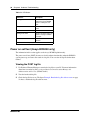
Table 10 Avaya BCM50 hardware reset functions
Reset Level
Description
Impact
Level 1
This reset erases all the
customer-specific data and
restores the default
configuration for all
components.
The LED illuminates yellow to
denote Level 1 reset.
Only the system and user
configuration data is erased
and replaced with default
values.
The software components are
not altered, that is, the system
will have the latest release and
patch level of the software
installed.
There will be no Ethernet
connectivity during this
operation.
Level 2
This reset erases all the
customer-specific data and
software releases and
patches.
This also resets the router
firmware to the original
configuration settings.
The LED illuminates red to
denote Level 1 reset.
The system re-installs the
original factory configuration
settings.
There will be no Ethernet
connectivity during this
operation.
Reboot
You can use the Reboot utility to:
•
•
•
•
reboot the Avaya BCM450 system
shut down the system
reboot the integrated router (BCM50a/e only)
create a scheduled reboot to take place at a specified time. This can be configured to occur
once, daily, weekly or monthly.
The table Reboot functions on page 29 lists the Reboot functions.
Table 11 Reboot functions
Function
Description
Impact
Reboot BCM450
System
Restarts the operating system of the Avaya Temporarily stops all services on the
BCM450 system.
system. Restarts all services.
This operation does not affect configuration
parameters or programming.
System Shutdown
Shuts down the Avaya BCM450.
Stops all services in preparation for
removing power from the system.
Add (Scheduled Reboot Allows you to create a new Scheduled
tab)
Reboot.
Troubleshooting Guide
30
Chapter 3 Hardware Troubleshooting
Table 12 LED Status
LED Status
Description
Blinking power LED
Indicates a user input
window; the Avaya BCM50
system is waiting for user
input.
Solid power LED
Indicates caution for extreme
action.
Red/Green
Level of reset
Blinking status LED
Indicates an interim state, the
system is trying to establish
user input.
Solid status LED
Indicates confirmation of user
selection
Note: Power LED has priority over Status LED.
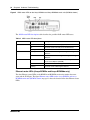
Power on self test (Avaya BCM450 only)
The information in this section applies to the Avaya BCM450 platform only.
The power on self test (POST) feature tests basic hardware functionality when the BCM450
system powers up, and stores the results in a log file. You can view the log file for hardware
failures.
Viewing the POST log file
1
Use Business Element Manager to transfer the log files to your PC. For more information
about how to transfer log files, see Avaya Business Communications Manager 6.0
Administration and Security (NN40170-603).
2
View the bootloader.log file.
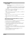
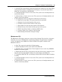
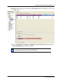
3
Check the log file for errors. The figure Example: Bootloader.log file with no errors on page
31 shows a bootloader.log file with no errors.
NN40170-700
Chapter 3 Hardware Troubleshooting
31
Figure 10 Example: Bootloader.log file with no errors
The figure Example: Boot file with errors on page 31 shows a file with errors.
Figure 11 Example: Boot file with errors
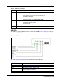
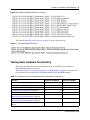
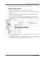
Testing basic hardware functionality
This section describes how to test the components of the Avaya BCM system, and how to
troubleshoot them if they fail the test.
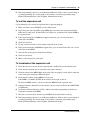
The table Procedures to test and troubleshoot Avaya BCM platform components on page 31 lists
the procedures to use to help isolate and identify problems with your BCM hardware:
Table 13 Procedures to test and troubleshoot Avaya BCM platform components
Procedure
Supported on BCM450
Supported on BCM50
To test the main unit on page 32
yes
yes
To troubleshoot the main unit on page 32
yes
yes
To test the expansion unit on page 33
yes
yes
To troubleshoot the expansion unit on page 33
yes
yes
Testing an MBM on page 34
yes
yes
Determining why an Avaya BCM450 MBM does not
appear in Business Element Manager on page 34
yes
no
Determining why an Avaya BCM50 MBM does not
appear in Business Element Manager on page 35
no
yes
Troubleshooting the FEM on the Avaya BCM450 on
page 35
yes
no
Troubleshooting Guide
32
Chapter 3 Hardware Troubleshooting
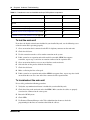
Table 13 Procedures to test and troubleshoot Avaya BCM platform components
Procedure
Supported on BCM450
Supported on BCM50
To determine why the ATA 2 does not function on page
35
yes
yes
To determine why there is no dial tone at the ATA2 on
page 36
yes
yes
To check the ATA2 wiring on page 36
yes
yes
Reset to factory settings on page 36
yes
yes
To perform a Level 1 reset (configuration reset) on page yes
40
yes
To perform a Level 2 reset (software reset) on page 40
yes
yes
To test the main unit
If you have the digital station feature included in your installed keycode, use the following test to
ensure the main unit is operating properly:
1
Go to an extension that is connected to the RJ-21 telephony connector on the main unit.
2
Check for a dial tone.
3
Use this extension to make a call to another extension on the system.
4
If this system has an expansion unit with a media bay module (MBM) that supports
extensions, repeat steps 3 and 4 for an extension connected to the expansion unit.
5
Go to an extension that has access to one of the lines on the main unit.
6
Select the line or line pool to which the line belongs.
7
Check for a dial tone.
8
Make a call using the line or line pool.
9
If this system has an expansion unit with an MBM that supports lines, repeat steps 6 to 8 with
an extension that can access one of the lines connected to the expansion unit.
To troubleshoot the main unit
If a test fails, perform the following procedure:
1
Verify that any nonfunctional feature is included in your installed keycode.
2
Check the wiring to the main unit and to the MBMs. Make sure that the cables are properly
seated and are connected to the correct ports.
3
Restart the BCM system.
4
Check LEDs.
5
Use Business Element Manager or the Telset Administration feature to check the
programming for the lines or extensions that failed the call test.
NN40170-700
Chapter 3 Hardware Troubleshooting
6
33
If the programming is incorrect, use the Backup and Restore Utility to load a recent backup of
system programming. If a recent backup is not available, correct the programming using
Business Element Manager or the Telephone Administration feature.
To test the expansion unit
Use the following test to ensure the expansion unit is operating properly:
1
Make sure that the Avaya BCM450 system is fully booted.
2
Check the power and status LEDs on the MBM that is inserted in the expansion unit. Both
LEDs must be solid green. If either LED is not solid green, a problem exists with the MBM or
the expansion unit.
3
If the expansion unit has an MBM that supports extensions, go to an extension that is
connected to the MBM.
4
Check for a dial tone.
5
Use this extension to make a call to another extension on the system.
6
If the expansion unit has an MBM that supports lines, go to an extension that has access to one
of the lines on the MBM.
7
Select the line or line pool to which the line belongs.
8
Check for a dial tone.
9
Make a call using the line or line pool.
To troubleshoot the expansion unit
1
Check that the correct feature for the expansion unit is included in your installed keycode.
2
Check that the expansion port is connected to the proper connector.
3
Check the wiring to the MBM. Make sure that the cables are properly seated and are connected
to the correct ports with proper LED indications.
4
Check that the switches on the MBM are all set to on.
If the MBM is a GASM or GATM, all the switches on the right are not on.
To check the MBM switches, you must remove the MBM from the expansion unit.
5
Perform a firmware download to ensure that the correct version is loaded on the ASM/GASM
or GATM unit.
6
Use Business Element Manager or Telset Admin to check the programming for the lines or
extensions connected to the MBM.
7
Restart the system to ensure that the Avaya BCM450 main unit functions correctly.
8
If the programming is incorrect, use the Backup and Restore Utility to load a recent backup of
system programming. If a recent backup is not available, correct the programming using
Business Element Manager or the Telephone Administration feature.
Troubleshooting Guide
34
Chapter 3 Hardware Troubleshooting
Testing an MBM
Perform the following procedure to test an MBM installed in the main unit or
expansion cabinet.
For Avaya BCM450, if you are experiencing an issue with an FEM, ensure all DIP
switches are set to the On position. The FEM is not supported on the BCM50
platform.
1
Check the Power and Status LEDs on the MBM. Both LEDs must be solid green. If either
LED is not solid green, a problem exists with the MBM.
2
Go to an extension on the MBM if it is a station MBM.
OR
Go to an extension that has access to one of the lines on the MBM if it is a trunk MBM. Select
the line or line pool to which the line belongs.
3
Check for a dial tone.
4
Use this extension to make a call to another extension on the system if it is a station MBM.
OR
Make a call using the line or line pool if it is a trunk MBM.
5
Use this extension to make a call to an external telephone number if you are testing a station
MBM.
Determining why an Avaya BCM450 MBM does not appear in
Business Element Manager
Use the following procedure if an installed MBM does not appear in Business Element Manager.
1
Check that the correct feature is included in your installed keycode.
2
Check that both the Power and Status LEDs on the MBM are solid green.
3
If the Power LED is off, and the MBM is installed in the expansion cabinet, check that the
power supply cable is properly seated in the expansion cabinet and the power supply is
connected to a working power outlet.
4
Ensure that the MBM is properly seated in the MBM bay.
5
If the Status LED is not solid green, and the MBM is installed in the expansion cabinet, check
that the Expansion cable is properly seated in the Expansion port on the expansion cabinet and
on the main unit.
6
Ensure that the MBM is enabled using either Business Element Manager or Telset
Administration. If the MBM is enabled, disable and re-enable it.
7
Ensure that all DIP switches are set correctly.
NN40170-700
Chapter 3 Hardware Troubleshooting
35
Determining why an Avaya BCM50 MBM does not appear in
Business Element Manager
1
Check that the correct feature for the expansion unit is included in your installed keycode.
2
Check that both the Power and Status LEDs on the MBM are solid green.
•
•
If the Power LED is off, check that the power supply cable is properly seated in the
expansion unit, and the power supply is connected to a working power outlet. Also check
that the MBM is properly seated in the expansion unit.
If the Status LED is not solid green, check that the expansion cable is properly seated in
the expansion port on the expansion unit and on the main unit.
3
Check that the MBM and expansion unit are enabled using either Business Element Manager
or Telset Administration. If the units are enabled, disable them, and then reenable them.
4
Check that all the switches on the MBM are on. If the MBM is a GASM or GATM, all the
switches on the right are not set to on. To check the MBM switches, you must remove the
MBM from the expansion unit. For more information, see the BCM50 Installation and
Maintenance Guide.
Troubleshooting the FEM on the Avaya BCM450
This procedure applies to the Avaya BCM450 only.
Perform the following procedure to troubleshoot an installed fibre expansion module (FEM).
1
Ensure that all six connector LEDs are lit.
2
If all six LEDs are not lit, ensure that all six DIP switches are set to the On (up) position.
To determine why the ATA 2 does not function
1
Check for a dial tone using an analog device.
2
Check that AC power is connected to the ATA 2 unit.
3
Check that the correct feature for digital sets is included in your installed keycode.
4
Verify that the ATA2 is connected to a digital station port.
5
Allow sufficient startup time (30–60 sec).
6
Plug an analog device into the phone port of the ATA2 and check for a dial-tone.
7
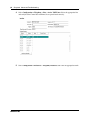
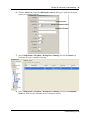
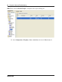
In Business Element Manager, verify that the ATA 2 is correctly configured:
a
Select Configuration, Telephony, Sets, All DNs.
b
Select the appropriate DN from the list and click the ATA settings tab.
The options for the Device Type are Modem or Telephone.
Troubleshooting Guide
36
Chapter 3 Hardware Troubleshooting
To determine why there is no dial tone at the ATA2
1
If you hear no dial tone, replace a single-line telephone for the data communication device.
2
If you hear no dial tone at the ATA2 unit:
a
Disconnect the line side of the ATA2. Connect a digital telephone to the ATA2 port.
b
Check that the connection from the ATA2 to the hardware works correctly.
To check the ATA2 wiring
1
Use an analog phone to test the ATA2.
2
Check the following connections:
a
ATA 2 to the terminal
The resistance must be 200 ohms or less for data applications and 1300 ohms or less for
voice applications.
b
Avaya BCM450 hardware to the ATA2
The wiring must be equivalent to 800 m of 0.5 mm wire (2600 ft. of 24-AWG) or less. Do
not use bridge taps and loading coils between the hardware and ATA2.
Reset to factory settings
This section describes how to reset the Avaya BCM system to the factory settings or a stable
working condition using the reset switch. When the BCM450 is in this condition, you can make
further modifications.
You can perform a Configuration Reset (previously known as a Level 1 reset), which restores
configuration settings to the factory default, or a Software Reset (previously known as a Level 2
reset), which resets the software and configuration to the factory default. Configuration and
Software resets are performed through the Command Line Interface (CLI) (see).
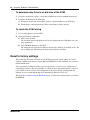
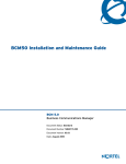
The figure Reset switch location on BCM450 on page 37 shows the location of the reset switch on
the BCM450.
NN40170-700
Chapter 3 Hardware Troubleshooting
37
Figure 12 Reset switch location on BCM450
Reset button
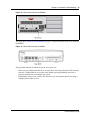
The figure Reset switch location on BCM50 on page 37 shows the location of the reset switch on
the BCM50.
Figure 13 Reset switch location on BCM50
Some possible situations in which you use the reset feature are:
•
•
If the system is configured incorrectly to an extent that it is no longer functional. The customer
must use a Configuration reset to return to the default system programming and restore a
previous configuration or reconfigure the system.
If distributors want to reuse systems, they must first erase all customer-specific data using a
Configuration or Software reset.
Troubleshooting Guide
38
Chapter 3 Hardware Troubleshooting
Reset levels
Reset to factory settings is a stand-alone feature that has the following levels of reset:
•
•
Configuration Reset (previously known as Level 1) reset erases all customer-specific data
and restores the default configuration for all components. This reset leaves the software
components untouched. That is, the system has the latest release and patch level of the
software installed. Only the system and user configuration data is erased and replaced with
default values. For the Avaya BCM50, no Ethernet connectivity to the system occurs during
this operation.
Software Reset (previously known as Level 2) reset erases all customer and system
configuration data and all software releases and patches. This reset reinstalls the original
factory configuration settings. For Avaya BCM50, a Software reset also resets the router
firmware to what was shipped from the factory. No Ethernet connectivity to the system occurs
during this operation.
Warning: If you perform a software reset to solve an undetermined problem and
still have access to Business Element Manager, you must retrieve all the log files
for technical support before performing the software reset. A software reset erases
all log files from the system.
Command Line Interface
You can use the Command Line Interface (CLI) to configure basic settings, as well as shut down,
reboot, or perform a Configuration or Software Reset on your Avaya BCM450 or Avaya BCM50
system. Two CLI modes are available: Maintenance CLI, and Configuration CLI.
Your user account must be assigned the System-CLI privilege in order to access the CLI.
Before performing a Configuration or Software reset, review all the effects of the levels of reset.
See Reset levels on page 38.
This section contains information about the following topics:
•
Configuration CLI on page 38
•
Maintenance CLI on page 39
Configuration CLI
The Configuration CLI displays when the system is in Main OS mode. The options available on
the Configuration CLI are
•
•
•
NN40170-700
0—Exit. The system exits the CLI to the login prompt.
1—Reboot. The system reboots to the Main OS.
2—Shutdown. The system shuts down. You need physical access to the BCM hardware to
restart the system.
Chapter 3 Hardware Troubleshooting
•
•
•
•
39
3—Safe OS. The system reboots to the Safe OS and waits 1 minute for you to login. When
you login within 1 minute, the Maintenance CLI displays. If you do not login within 1
minute, the system changes to the Main OS.
4—Configuration Reset. A Level 1 reset occurs. The system resets all configuration data
to the factory defaults.
5—Software Reset. A Level 2 reset occurs. The system resets all configuration data and
software to the factory defaults.
6—IP Configuration. You can configure the following basic IP settings:
— 0—Return to Previous Menu. The system returns to the main menu.
— 1—Hostname. Provision the hostname of the system.
— 2—IP Address. Provision the IP address of the system.
— 3—Subnet Mask. Provision the subnet mask for the IP address.
— 4—Default Gateway. Provision the default gateway for the system.
— 5—DHCP Client Mode. Enable or disable the DHCP client.
— 6—Commit Changes. Save changes to the IP settings.
— 7—Reload Settings. Reload the existing IP settings.
Maintenance CLI
The Maintenance CLI displays when the system is in Safe OS mode. The Safe OS is a diagnostic
mode that you can use if the Main OS is experiencing problems. No applications or telephony
services run when the Avaya BCM 6.0 is in Safe OS mode. The options available on the
Maintenance CLI are
•
•
•
•
•
•
•
0—Exit. The system exits to the Safe OS login prompt.
1—Reboot into Main OS. The system reboots to the Main OS.
2—Shutdown. The system shuts down. You need physical access to the Avaya BCM450
hardware to restart the system.
3—Reboot into Safe OS. The system reboots to the Safe OS and waits 1 minute for you to
login. If you do not login within 1 minute, the system changes to the Main OS.
4—Transition to Main OS. The system changes from the Safe OS to the Main OS without
restarting.
5—Configuration Reset. A Level 1 reset occurs. The system resets all configuration data
to the factory defaults.
6—Software Reset. A Level 2 reset occurs. The system resets all configuration data and
software to the factory defaults.
Troubleshooting Guide
40
Chapter 3 Hardware Troubleshooting
To perform a Level 1 reset (configuration reset)
1
Access the CLI. For more information about how to access the CLI, see Command Line
Interface on page 90.
2
From the Configuration CLI, select option 4—Configuration Reset. If you are using the
Maintenance CLI, select option 5—Configuration Reset.
3
The LEDs progress through the start-up and shut down sequence. This process can take more
than 2 minutes.
4
A Status LED that is flashing yellow, and a Power LED that is solid red, indicates that a
configuration reset is in progress. This process can take more than 2 minutes.
5
The system restarts to the Main OS. This process can take more than 2 minutes.
To perform a Level 2 reset (software reset)
1
Access the CLI. For more information about how to access the CLI, refer to Command Line
Interface on page 90.
2
From the Configuration CLI, select option 5—Software Reset. If you are using the
Maintenance CLI, select option 6—Software Reset.
3
The LEDs will progress through the start-up and shut down sequence. This process can take
more than 2 minutes.
4
A Status LED that is flashing yellow, and a Power LED that is solid red, indicates that a
software reset is in progress. This process can take more than 5 minutes.
5
The system restarts to the Main OS. This process can take more than 2 minutes.
Monitoring the boot process (Avaya BCM450 only)
1
Connect a serial cable with a 9-pin female connector from the serial port on a PC to the serial
port on the Avaya BCM450.
2
Ensure that you use the following settings:
•
•
•
•
•
bits per second: 115200
data bits: 8
parity: N
stop bits: 1
no flow control
3
Use a terminal emulation program, such as Hyperterminal or Avaya CLI Manager, to establish
a connection to the BCM450.
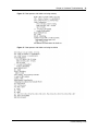
4
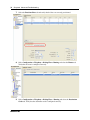
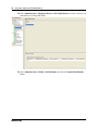
Restart the system and observe the boot process. Figure 14 shows an example of a boot
process when there is failed or missing memory; Figure 15 shows an example of a boot
process when there is a failed or missing hard drive.
5
If the system starts normally, the CLI login prompt displays when the boot cycle is complete.
NN40170-700
Chapter 3 Hardware Troubleshooting
41
Figure 14 Boot process with failed or missing memory
Figure 15 Boot process with failed or missing hard drive
Troubleshooting Guide
42
Chapter 3 Hardware Troubleshooting
NN40170-700
Chapter 4 Initial Troubleshooting
43
Chapter 4
Initial Troubleshooting
The information in this chapter applies to both the Avaya BCM50 and the Avaya BCM450
platforms running Avaya Business Communications Manager (Avaya BCM) 6.0.
You can better troubleshoot the problems on your network and reduce their impact by preparing
for such events in advance. To do this, you must know the following:
•
•
•
that your system is properly installed and routinely maintained
the configuration of your network
the normal behavior of your network
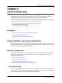
Navigation
•
•
•
Proper installation and routine maintenance on page 43
Network configuration on page 43
Normal behavior on your network on page 44
Proper installation and routine maintenance
For more information about detailed installation information, see Avaya Business Communications
Manager 6.0 Installation—System (NN40170-303).This document also outlines the routine tasks
required for operating the BCM50 and BCM450.
Network configuration
To keep track of your network’s configuration, gather the information described in the following
sections. This information, when kept up-to-date, is extremely helpful when you experience
network or device problems.
•
•
•
•
Site network map on page 43
Logical connections on page 44
Device configuration information on page 44
Other important data about your network on page 44
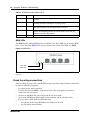
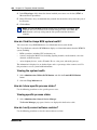
Site network map
A site network map identifies where each device is physically located on your site, which helps
locate the users and applications that are affected by a problem. You can use the site network map
to systematically search each part of your network for problems.
Troubleshooting Guide
44
Chapter 4 Initial Troubleshooting
Logical connections
With virtual LANs (VLANs), you must know how your devices are connected logically as well as
physically.
Device configuration information
You should maintain online and paper copies of your device configuration information. Ensure
that all online data is stored with your site’s regular data backup. If your site does not have a
backup system, copy the information onto a backup disk (such as a CD or zip disk) and store the
backup disk at an offsite location.
Other important data about your network
For a complete picture of your network, have the following information available:
•
•
•
•
•
All passwords—Store passwords in a safe place. It is a good practice to keep records of your
previous passwords in case you must restore a device to a previous software version and need
to use the old password that was valid for that version.
Device inventory—It is a good practice to maintain a device inventory, which list all devices
and relevant information for your network. The inventory allows you to easily see the device
type, IP address, ports, MAC addresses, and attached devices.
MAC address-to-port number list—If your hubs or switches are not managed, you must
keep a list of the MAC addresses that correlate to the ports on your hubs and switches.
Change control—Maintain a change control system for all critical systems. Permanently store
change control records.
Contact details—It is a good practice to store the details of all support contracts, support
numbers, engineer details, and telephone and fax numbers. Having this information available
when troubleshooting can save a lot to time.
Normal behavior on your network
When you are familiar with the performance of your network when it is fully operational, you can
be more effective at troubleshooting problems that arise. To understand the normal behavior of
your network, monitor your network over a long period of time. During this time you can see a
pattern in the traffic flow, such as which devices are typically accessed or when peak usage times
occur.
To identify problems, you can use a baseline analysis, which is an important indicator of overall
network health. A baseline serves as a useful reference of network traffic during normal operation,
which you can then compare to captured network traffic while you troubleshoot network
problems. A baseline analysis speeds the process of isolating network problems. By running tests
on a healthy network, you compile normal data for your network. This normal data can then be
used to compare against the results that you get when your network is experiencing trouble. For
example, ping each node to discover how long it typically takes to receive a response from devices
on your network. Capture and save each device’s response time and when you are troubleshooting
you can use these baseline response times to help you troubleshoot.
NN40170-700
Chapter 5 Software Troubleshooting
45
Chapter 5
Software Troubleshooting
The information in this chapter applies to both the Avaya BCM 50 and the Avaya BCM450
platforms running Avaya Business Communications Manager (BCM) 6.0.
Use the information in this chapter to troubleshoot problems related to the BCM software
components.
Navigation
Complete the following tasks, in the order shown below, to troubleshoot some of the common
problems that you can encounter with the Avaya BCM software:
•
•
•
•
•
Verify the software version on page 45
Verify the keycodes on page 45
Check the programming of lines and phones on page 45
Restoring system data on page 54
Verify the software inventory on page 55
Verify the software version
In the Business Element Manager, select Help, About. A panel displays and provides information
about the Business Element Manager, such as the Release level.
Verify the keycodes
If a specific feature is not functioning, verify that the feature is included in your installed
keycodes. For information about how to verify the installed keycodes, see Verify the keycodes on
page 27.
Check the programming of lines and phones
You can use the Business Element Manager to view the programming of lines and phones. When
you view the lines, the information on the panels may vary, depending on the type of line.
The Business Element Manager displays line information in two sections:
•
•
The main section, Trunk/Line data, is located at the top of the screen and provides a table of
lines and the current or default settings.
The bottom section contains three tabs. The contents of the tabs may vary, depending on the
line selected in the top table.
Troubleshooting Guide
46
Chapter 5 Software Troubleshooting
— The Properties tabbed panel provides the settings for individual line characteristics.
— The Preferences tab shows information that may vary from trunk to trunk
— The Restrictions tabbed panel allows you to define which restrictions will be active for
individual lines. Note that lines that are assigned to the same line pool will automatically
assign the same restrictions.
— The Assigned DNs tabbed panel provides a quick way to assign lines to telephones. You
must use the DN records panels to assign line pools to telephones.
Check line programming
Use the following procedure to check line programming in your Avaya BCM system.
To check line programming
1
In the Task Navigation Panel, select the Configuration tab.
2
Select Telephony > Lines.
3
Verify that the programming for all lines is correct; see Trunk/Line data on page 46 for an
explanation of the fields on the panel.
4
Select a line, and then select a tab:
a
Select the Properties tab and verify that the settings are correct; see Properties on
page 48 for an explanation of the fields on the tab.
b
Select the Preferences tab and verify that the settings are correct; see Preferences on
page 49 for an explanation of the fields on the tab.
c
Select the Restrictions tab and verify that the settings are correct; see Restrictions on
page 52 for an explanation of the fields on the tab.
d
Select the Assigned DNs tab and verify that the settings are correct; see Assigned
DNs on page 53 for an explanation of the fields on the tab.
5
Repeat step 4 for the remaining lines.
6
Correct any programming problems, or restore the system data; for more information, see
Restoring system data on page 54.
Trunk/Line data
The top-level Table View panel shows line records for all lines active on the system, and the
common assigned parameters.
NN40170-700
Chapter 5 Software Troubleshooting
47
The table Trunk/Line Data main panel on page 47 describes the fields found on the Trunk/Line
Data main panel.
Table 14 Trunk/Line Data main panel (Sheet 1 of 2)
Attribute
Value
Description
Line
Configure only those lines that are active on the system.
This list contains all the
(Click the Active check box and ensure that the Inactive
possible line numbers for
the system, including target check box is empty).
lines.
Trunk Type
PSTN-based lines, VoIP,
Target
There are three main categories of lines:
PSTN-based lines: (analog, T1, PRI, BRI)
Voice over IP (VoIP) trunks, which connect through the LAN
or WAN.
Target lines, which are internal channels that provide direct
dial capability.
Name
<maximum of seven
alphanumeric characters>
Identify the line in a way that is meaningful to your system,
such as by the type of line and line pool or the DN it is
attached to in the case of target lines.
Control Set
DN <control telephone DN> Enter a telephone DN for a telephone that you want to use
to turn service off or on for other telephones using this line.
Default: 221 (default Start
DN)
The control telephone must have the line assigned, or must
be assigned to the line pool the line is in.
Tips: External lines and telephones must be programmed to use one of the Scheduled
Services: Ringing, Restriction, and Routing Services.
For maximum flexibility, Avaya recommends that you create two different control
telephones, one for the lines and one for the telephones.
You can turn on a service manually or automatically for all external lines from an assigned
control telephone. However, you cannot combine schedules. A service can only be active
as normal service or one of the six schedules at any one time. Several schedules can be
active at one time, but they must use different services.
Line Type
Define how the line is used in relation to other lines in the
Public
Private to: <telephone DN> system.
• Public line: can be accessed by more than one
Pool A to O,
telephone.
BlocA to BlocF
• Private line: can be assigned only to one telephone and
the prime telephone for that line. Enter the internal
number of the telephone.
• Pool A - O (analog and T1 lines) BlocA to BlocF
(PRI and VoIP lines): assigns the line to one of the line
pools. If a line is assigned to a line pool, but is not
assigned to any telephone, that line is available only for
outgoing calls.
Bloc line pools must be used in conjunction with routes
and destination codes. Target lines cannot be put into
line pools.
Troubleshooting Guide
48
Chapter 5 Software Troubleshooting
Table 14 Trunk/Line Data main panel (Sheet 2 of 2)
Attribute
Value
Description
Prime set
DN: <telephone DN>
None
Assign a telephone to provide backup answering for calls
on the line. For an Auto Answer line, calls are redirected if
the received number is invalid or the target line is busy, and
if the
If busy parameter is set To prime.
Each line can be assigned only one prime telephone.
Pub.
Received #
(Target lines
only)
<digits associated with a
specific target line>
Specify the digits the system will use to identify a call from
the public network to this target line.
• A received number cannot be the same as, or be the
start digits, of a line pool access code, a destination
code, the DISA DN or the Auto DN.
• If you are configuring auto-answer BRI trunks to map to
target lines, the received number should be the same as
the Network DN supplied by your service provider. The
call will be directed to the prime telephone for the
incoming line if the Network DN is not used.
Priv.
Received #
(Target lines
only)
<digits associated with a
specific target line>
Specify the digits the system will use to identify a call from
the private network to this target line.
• A received number cannot be the same as, or be the
start digits, of a line pool access code, a destination
code, the DISA DN or the Auto DN.
• If you are configuring auto-answer BRI trunks to map to
target lines, the received number should be the same as
the Network DN supplied by your service provider. The
call will be directed to the prime telephone for the
incoming line if the Network DN is not used.
Distinct ring
None
Pattern 2
Pattern 3
Pattern 4
Choose the distinctive ring pattern that you want to assign
to the line. This allows you to provide selective service to
calls with differing answer priorities.
When more than one line with the distinct ring settings rings
at a telephone, the line with the highest priority rings first.
• Pattern 4 has the highest ring priority
• Pattern 3 has second highest ring priority
• Pattern 2 has third highest ring priority
• None has the lowest ring priority.
By default, all telephones and lines are set to None.
Properties
The Properties tab shows basic line properties. Not all fields apply to all types of lines.
The Properties tab is shown in the figure Properties details panel on page 49.
NN40170-700
Chapter 5 Software Troubleshooting
49
Figure 16 Properties details panel
The table Properties line settings on page 49 defines the fields on this panel and indicates the lines.
Table 15 Properties line settings
Attribute
Value
Description
Legend: Loop = analog/digital loop; GS = ground start; DID = DID; E&M = E&M; BRI = BRI; DPNSS
= DPNSS; VoIP = VoIP; TL = Target. Note: PRI fields are all included under the main table.
Loss package
Line Tuning Digit
Loop (analog
only)
Short CO
Medium CO
Long CO
Short PBX
Long PBX
Select the appropriate loss/gain and impedance settings for
each line.
drop-down menu
Select the line tuning digit to use. When a trunk is connected,
the Avaya BCM 6.0 starts a call and sends this digit to the CO
to turn off the dial tone signal, and then tests the line to optimize
the trunk levels. The default digit is 1. You may need to change
the default digit if your CO uses the digit 1 to route the call to a
special service or to a second dial tone or busy/re-order tone.
Select the digit that will result in silence on the trunk.
Preferences
The Preferences tab shows information that may vary from trunk to trunk. Most of this information
needs to coordinate with the line service provider equipment.
The figure Preferences details panel on page 50 shows the Preferences tab.
Troubleshooting Guide
50
Chapter 5 Software Troubleshooting
Figure 17 Preferences details panel
The table Preferences details fields for lines on page 50 defines the fields on this panel and
indicates the lines.
Table 16 Preferences details fields for lines (Sheet 1 of 3)
Attribute
Value
Description
Legend: Loop = analog/digital loop; GS = ground start; DID = DID; E&M = E&M; BRI = BRI; DPNSS
= DPNSS; VoIP = VoIP; TL = Target and DASS2. Note: PRI fields are all included under the main
panel.
Auto privacy
Loop
GS
<check box>
Full autohold
Aux. ringer
DID
E&M
BRI
VoIP
Define whether one Avaya BCM450 user can select a line in
use at another telephone to join an existing call.
Loop
BRI
DPNSS
VoIP
<check box>
Enables or disables Full autohold.
When enabled, if a caller selects an idle line but does not dial
any digits, that line is automatically placed on hold if you then
select another line.
Full autohold is always in place for T1 E&M trunks because it
has no meaning for incoming-only T1 DID trunks.
The default setting should be changed only if Full autohold is
required for a specific application.
Loop
DID
GS
<check box>
E&M
BRI
DPNSS
VoIP
TL
Turn the auxiliary ringer on or off for all telephones using this
line.
When programmed on a line, the auxiliary ringer will ring every
time a call is received.
Note: When programmed only on a telephone, no ring occurs for a transferred call.
An auxiliary ringer can also be programmed in Services to ring for a line placed into
a scheduled Ringing service.
NN40170-700
Chapter 5 Software Troubleshooting
51
Table 16 Preferences details fields for lines (Sheet 2 of 3)
Attribute
Value
Description
Legend: Loop = analog/digital loop; GS = ground start; DID = DID; E&M = E&M; BRI = BRI; DPNSS
= DPNSS; VoIP = VoIP; TL = Target and DASS2. Note: PRI fields are all included under the main
panel.
ANI Number
DID
<check box>
DNIS Number
E&M
Define whether the telephone number of the caller will be
shown for this line.
For T1 E&M and T1 DID trunks connected to a DTM, this setting
only appears if Signaling is set to WinkStart.
The central office must deliver ANI/DNIS in DTMF mode. No
additional equipment is required.
E&M
<check box>
Defines whether the digits dialed by an external caller on this
line will be shown.For T1 E&M trunks connected to a DTM, this
setting only appears if Signaling is set to WinkStart and Answer
mode is set to Manual.
Distinct Rings in
use
<read-only>
Indicates if a special ring has been assigned. See Distinct Ring
on the main table.
Answer mode
Loop
GS
Manual
Auto
E&M
BRI
DPNSS
Define whether a trunk is manual or automatic answer.
Auto answer mode allows the trunk to be a shared resource by
the system telephones. This shared resource is created through
routing to target lines or using DISA.
For auto answer trunks being used to allow remote call-in from
system users, the trunk can be configured to answer with a
straight dial tone, if DISA has not been enabled. It can also be
configured to answer with a stuttered dial tone if DISA is
enabled and the caller is expected to enter a CoS password.
The CoS password defines which system features the caller is
permitted to access.
Manual answer trunks are assigned to one or more telephones.
The assigned telephones exclusively own the line.
Note: You require Disconnect supervision on the line if loop start trunks are to
operate in auto-answer mode.
Answer with DISA
Loop
GS
<check box>
If busy
E&M
BRI
Define whether the system prompts a caller for a six-digit class
of service (CoS) password. This setting appears for T1 loop
start, T1 E&M lines that have auto-answer mode, and analog
trunks. Set this option to No for T1 E&M lines on a private
network that have auto-answer mode.
TL
To Prime
Busy Tone
Define whether a caller receives a busy tone or the call
forwards to the prime telephone when the target line is busy.
Busy tone only works for PRI trunks.
Tips: The duration of an open switch interval (OSI) before BCM450 disconnects a
call is programmed by the Disconnect timer setting.
Troubleshooting Guide
52
Chapter 5 Software Troubleshooting
Table 16 Preferences details fields for lines (Sheet 3 of 3)
Attribute
Value
Description
Legend: Loop = analog/digital loop; GS = ground start; DID = DID; E&M = E&M; BRI = BRI; DPNSS
= DPNSS; VoIP = VoIP; TL = Target and DASS2. Note: PRI fields are all included under the main
panel.
Voice Message
Center
Redirect to
Loop
GS
Center 1 Center 5
Loop
DID
E&M
BRI
DPNSS
VoIP
TL
If this line connects t o a remote voice mail, either through the
private network or at the Central Office, indicate which Center
number has been configured with the contact number.The
system calls that number to check voice mail messages when a
message indicator is presented to a telephone.
GS
<dial string>
DID
E&M
TL
Enter a dial string (including destination code) to redirect the
line to an external telephone, such as a call attendant on
another system.
If you want to stop redirection, you need to delete the dial string
and allow the record to update.
Warning: If the dialstring is set up, the line will immediately be
redirected out of the system not ringing any telephone.
Warning: Enable modules
If you disabled any trunk media bay modules prior to performing programming, enable them now to
ensure your system will function properly.
Restrictions
Assigning Line restrictions and Remote Access Package restrictions are part of the configuration
for controlling calls out of the system (line restrictions) and into the system from a private network
node or from a remote user calling in over the PSTN lines (Remote Access Packages).
The figure Restrictions tab on page 53 shows the restrictions for a line.
NN40170-700
Chapter 5 Software Troubleshooting
53
Figure 18 Restrictions tab
The table Restrictions on page 53 describes the fields on this panel.
Table 17 Restrictions
Attribute
Values
Use remote package <remote package #>
Description
If the line is being used to receive external calls or calls
from other nodes on the private network, ensure that
you indicate a remote package that provides only the
availability that you want external callers to have. This
attribute is typically used for tandeming calls.
Schedule
Default: Normal, Night, Evening, Lunch, Sched 4, Sched 5, Sched 6
Line Restrictions Use Filter
<00-99>
Enter the restriction filter number that applies to each
schedule.
(controls outgoing calls)
Remote Restrictions
- Use Filter
<00-99>
Enter the restriction filter that applies to each schedule.
This setting provides call controls for incoming calls over
a private network or from remote user dialing in over
PSTN)
Assigned DNs
The Assigned DNs tabbed panel displays the DN properties for lines that are assigned to
telephones.
This information can also be configured on the DN record. Any information added, deleted or
modified in this table reflects in the DN record.
Note: Lines that do not allow single-line assignment, such as PRI lines and VoIP lines,
will not display this tabbed panel.
Troubleshooting Guide
54
Chapter 5 Software Troubleshooting
Restoring system data
If the programming of lines and extensions is incorrect, you can restore from an archive file, or
you can restore the system to factory defaults. This section provides the procedures to follow to
restore system data from an archive file, and to restore factory defaults. For information about the
effects of performing a restore operation, or about optional components, see Avaya Business
Communications Manager 6.0 Administration and Security (NN40170-603).
Restoring data from an archive
Caution: A backup operation can interrupt services running on the Avaya BCM.
A warning displays whenever the backup will cause a service interruption. If you
want to perform a backup that does not affect the system, you can exclude
services that would be affected. Alternatively, you can include these services and
perform a backup at a time when the system is typically not in use.
To restore data from an archive
1
In the task panel, click the Administration tab.
2
Open the Backup and Restore folder, and then click Restore.
The Restore panel opens. The Restore From selection field has Avaya BCM as a default
value.
3
In the Restore From selection field, select the location of the archive file to restore:
•
•
•
•
•
•
•
BCM
My Computer
Network folder
FTP server
SFTP server
USB storage device
Factory Default
4
Click the Restore button.
The Select Components to Restore window opens.
5
Select the optional components that you want to include from the backup file.
6
Click the OK button.
A warning window opens and displays information about components that will be affected by
the restore operation. Read the warning carefully before proceeding.
7
Click the Yes button to proceed.
A progress window opens. When the operation is complete, the Restore Complete window
opens.
8
Click the OK button.
NN40170-700
Chapter 5 Software Troubleshooting
55
Restoring the factory configuration
Caution: A restore operation is a service-affecting operation. A number of
services running on the Avaya BCM system are stopped and then restarted using
the restored configuration or application data. A reboot is required if you choose
Keycodes as a restore option. It will take several minutes before Voicemail is
working again.
To restore the factory configuration
Your Avaya BCM is delivered with a backup file that was created at the factory. This file can be a
helpful starting point if you decide to completely reconfigure your BCM and you want to erase the
settings programmed on your device. Although you can select individual components to restore,
Avaya recommends that you restore all components when using this option.
1
In the task panel, click the Administration tab.
2
Open the Backup and Restore folder, and then click Restore.
The Restore panel opens.
3
In the Restore From selection field, select Factory Default.
A warning dialog box displays.
4
Click the Restore button.
The Select Components to Restore panel opens.
5
Select the optional components that you want to include from the backup archive.
6
Click the OK button.
A warning window opens and displays information about components that will be affected by
the restore operation. Read the warning carefully before proceeding.
7
Click the Yes button to proceed.
A progress window opens. When the operation is complete, the Restore Complete window
opens.
8
Click the OK button.
Verify the software inventory
This section provides information about how to verify the level of software components and obtain
updates to your software inventory. For information about applying software updates, see Avaya
Business Communications Manager 6.0 Administration and Security (NN40170-603).
Viewing the inventory of Avaya BCM software
Avaya BCM software is organized into software components that you can individually update as
required. The version of each software component is tracked so that you can determine the exact
software release level of a BCM to the component level.
Troubleshooting Guide
56
Chapter 5 Software Troubleshooting
You can view the complete inventory of software installed on the BCM. The Software Inventory
table displays all the software components installed on the system, the functional group and the
software version of each component.
The table Information displayed in the Software Component Version Information table on page 56
lists the information displayed in the Software Component Version Information table.
Table 18 Information displayed in the Software Component Version Information table
Column
Description
Component
The name of the software component installed on the BCM450. For
example, backup-recovery.
Group
The functional group to which the software component belongs. For
example, Operating System.
Version
The version of the software component.
You can change the order of the information displayed in the table by clicking a column heading
and dragging it to a new place in the table. You can also sort the information in a column by
descending or ascending order, by clicking the column heading.
To view the Avaya BCM software inventory
1
In the task panel, click the Administration tab.
2
Open the Software Management folder, and then click the Software Inventory task.
The Software Inventory panel opens.
3
View the details in the Software Component Version Information table.
Obtaining software updates
Before you can apply a software update to your Avaya BCM, you must obtain the software update
and unzip the file. Authorized Avaya partners can download BCM software updates from the
Avaya Technical Support web page. For more information about obtaining updates from the
Avaya Technical Support web page, see www.avaya.com/support.
NN40170-700
Chapter 6 Advanced Troubleshooting
57
Chapter 6
Advanced Troubleshooting
The information in this chapter applies to both the Avaya BCM50 and Avaya BCM450 platforms
running Avaya Business Communications Manager (BCM) 6.0.
This chapter contains examples of advanced troubleshooting procedures. You must be a system
administrator to perform these procedures.
Navigation
•
•
•
•
•
•
•
•
Example 1: Cannot dial out from an analog trunk on page 57
Example 2: Cannot dial out from a SIP or H323 VoIP trunk on page 62
Example 3: IP set is not registering with the Avaya BCM on page 68
Example 4: Cannot install keycode or invalid keycode application on page 70
Example 5: Cannot dial out from digital trunk on page 70
Example 6: MeetMe Conferencing commands do not work, or conferencing is busy on page
75
Example 7: Unable to apply a software update from a USB storage device on page 76
Example 8: Business Element Manager incorrectly shows expansion cabinet as empty on page
77
Example 1: Cannot dial out from an analog trunk
When you cannot dial out from an analog trunk, you may experience the following problems in
your network:
•
•
•
•
•
you are unable to reach a destination number when you dial it
there is no dial tone
instead of a dial tone, you hear a re-order or fast-busy tone
you hear a “wrong number” message from the central office
if you are attempting to make a Find Me/Follow Me call, your external destinations do not
ring, or stop before you pick up the call
Use the following procedure when you cannot dial out from an analog trunk.
Troubleshooting example 1a
1
Check that the LED indicators on the Avaya BCM Chassis and the MBM are solid green.
2
Using an analog test set, verify that a dial tone is present at the MBM termination point.
Troubleshooting Guide
58
Chapter 6 Advanced Troubleshooting
3
From the Business Element Manager, select Configuration > System > Keycodes to view the
list of installed features.
4
Verify that the appropriate keycode is active. For analog trunk modules, the keycode is Exp
Port, and for BCM50 built-in trunks (main chassis), the keycode is Int Analog Trunk.
5
Select Configuration, Resources > Telephony Resources and select the appropriate trunk.
Verify that the trunk is active.
6
Select Configuration, Telephony > Lines > Active Physical Lines. Select the appropriate
line and verify that it is provisioned correctly. The Line Type should be Pool A, the Trunk
Mode should be Supervised, and the Dial Mode should be Tone.
7
Select Configuration, Telephony > Sets > Active Sets. Select the appropriate set and verify
that it is provisioned correctly. On the Line Assignment tab, verify that the Appearance Type
is one of the following: appear only, appear and ring, or ring only.
8
Select Administration > Utilities > BCM Monitor, and then click Launch BCM Monitor.
NN40170-700
Chapter 6 Advanced Troubleshooting
9
59
Select the BCM Info tab and verify the status of the line.
Troubleshooting example 1b
1
If you are attempting to use Find Me/Follow Me over an analog trunk, log on to Set Based
Admin. For more information about Set Based Admin, see Avaya Business Communications
Manager 6.0 Telset Administration Guide (NN40170-604).
2
To ensure that Voice Activity Detection is enabled, navigate to System prgrming> AnlgTrks
VAD > VAD Enabled. If VAD Disabled appears as a parameter instead, then Voice Activity
Detection is disabled.
3
If VAD is enabled and Find Me/Follow Me calls are still being dropped, adjust the VAD
parameters to account for line noise. Table 19 on page 60 details the available VAD parameters
available under System prgrming> AnlgTrks VAD > VAD Parameters.
Troubleshooting Guide
60
Chapter 6 Advanced Troubleshooting
Table 19 VAD Parameters
Parameter
Description
SpchSlow
The system uses this value
when the DSP VAD algorithm
detects a "possible tone" or
"unwanted spike" and delays
speech detection for this value
times 10 milliseconds (default
= 10, or 100 milliseconds).
You must adjust this value for
each analog trunk. This value
can be increased to prevent a
VAD misdetection.
Range = 10 - 32767.
SpchFast
The system uses this value to
delay speech detection by 10
milliseconds for every
increment of one. The default
value is 6 meaning that it takes
at least 60 milliseconds to
detect speech.
In normal circumstances this
value should not change. In
some situations where the call
progress tones are received
with fluctuations in energy
level, increasing this value may
prevent false VAD detection at
the cost of delaying actual
speech detection.
Range = 1 - 10.
NoiseFloor
This value is the average noise
level in the channel. The
speech detection algorithm
considers a signal as valid
speech if its short term
average energy in the past 50
milliseconds is greater than
this value, otherwise it will
consider this as noise.
The value can be converted to
dB using this formula:
Noise floor in dB =
Log10(NOISE_FLOOR/
2^20)*10;
The default value is 10 so the
noise level is between -50dB to
-15dB.
Range = 0 - 65535
NN40170-700
Chapter 6 Advanced Troubleshooting
Parameter
Description
EdgeThrsh
This value is the minimum
energy level before sound can
be considered an "edge of a
tone" energy or "unwanted
spike". The value can be
converted to dB using this
formula:
Edge Threshold in dB =
Log10(EDGE_THRESHOLD/
2^20)*10;
The default value is 900, so all
spikes in the channel with
more than -30dB and have
been jumped in energy level by
a factor of PeakRatio will be
delayed for speech detection
by the SpchSlow value.
Increasing this value will
improve speech detection time
at the cost of possible
misdetection when there is any
unwanted spike in the channel.
You must adjust this value for
each analog trunk. The
minimum value of this
parameter is the minimum
energy of an "unwanted spike"
for all analog trunks in the
system.
Range = 0 - 65535
PeakRatio
The DSP VAD algorithm uses
this value to detect the start of
a "possible tone" or an
"unwanted spike".
The default value of this
parameter is 10 meaning that
the average energy in the last
20 milliseconds must be 10
times bigger or smaller than
the current energy to be
considered as a "possible
rising/falling edge" of tone
energy or a possible spike.
You can decrease this value for
channels with weak progress
tones and VAD misdetection.
You can increase this value if
there is a delay in speech
detection. Lowering the
number causes more delay in
speech detection. Higher
numbers increase the
possibility of VAD misdetection
for low amplitude call progress
tones.
Range = 1 - 4095
61
Troubleshooting Guide
62
Chapter 6 Advanced Troubleshooting
Parameter
Description
FixFrmNum
This value indicates the
minimum number of speech
frames in the past 10 frames.
Each speech frame is 10
milliseconds.
The system uses this value to
detect the rising and falling
edges of a tone. You can
decrease this value for tones
with significant fluctuation
during the tone ON period. You
can increase this value to
increase the speech detection
time at the cost of possible
misdetection during a call
progress tone.
Range = 1 - 10
VarFrmNum
This value indicates the
minimum number of frames in
the past 10 frames that violate
the steady state condition after
a possible tone edge detection.
Each speech frame is 10
milliseconds.
This value detects the rising
and falling edges of a tone. You
can increase this value to
increase the speech detection
time at the cost of possible
misdetection during a call
progress tone.
Range = 1 - 10
Example 2: Cannot dial out from a SIP or H323 VoIP trunk
When you cannot dial out from a SIP or H323 VoIP trunk, you may experience the following
problems in your network:
•
•
you are unable to reach a destination number when you dial it
there is no route to the destination
Use the following procedure when you cannot dial out from a SIP or H323 trunk.
Troubleshooting example 2
1
Check that the LED indicators on the Avaya BCM Chassis are solid green.
2
From the Business Element Manager, select Configuration > System > Keycodes to view the
list of installed features.
NN40170-700
Chapter 6 Advanced Troubleshooting
3
63
Verify that the appropriate keycode is active. For H323 trunks, the keycode is VoIP GW
Trunk, and for SIP trunks, the keycode is SIP GW Trunk.
Troubleshooting Guide
64
Chapter 6 Advanced Troubleshooting
4
Select Configuration > Telephony > Line > Active VoIP Lines. Select the appropriate line
and verify that the Control Set and Prime Set are provisioned correctly.
5
Select Configuration > Resources > Telephony Resources and select the appropriate trunk.
NN40170-700
Chapter 6 Advanced Troubleshooting
6
Click the Add button to open the Add Remote Gateway dialog box. Verify that the remote
gateway is configured correctly.
7
Select Configuration > Telephony > Dialing Plan > Routing and select the Routes tab.
Verify that the route is configured correctly.
8
Select Configuration > Telephony > Dialing Plan > Routing and select the Destination
Codes tab. Verify that the destination code is configured correctly.
65
Troubleshooting Guide
66
Chapter 6 Advanced Troubleshooting
Note: Ensure that the Absorbed Length is configured to the expected dialing plan.
9
Select Configuration > Telephony > Sets > Active Sets and select the Line Access tab.
NN40170-700
Chapter 6 Advanced Troubleshooting
67
10 Highlight the appropriate set and select the Line Pool Access tab. Verify that the set has access
to VoIP trunks
11 Select Configuration > Telephony > Dialing Plan > Private Network and ensure that the
Private Network Type is set to CDP or UDP.
Note: In this example, the dialing plan is configured for a CDP Network with the
recommended minimum 4 digit Private DN length.
Troubleshooting Guide
68
Chapter 6 Advanced Troubleshooting
Example 3: IP set is not registering with the Avaya BCM
When an IP set cannot register with the Avaya BCM450, you notice the following problem in your
network:
•
the IP set is not registered and repeatedly tries to connect to the BCM
If an IP phone is not registering with the BCM, there are three possible causes:
•
•
•
there are not enough licenses for the number of IP phones connected to the system
the number of IP sets connected exceeds the maximum: the maximum for BCM450 is 300 and
the maximum for BCM50 is 32
the phone is not correctly configured
Verify that the number of phones does not exceed the number of licenses. If there are too many
phones for the number of licenses, disconnect unnecessary phones, or increase the number of
licenses.
If the number of IP sets connected to the Avaya BCM exceeds the maximum number of IP set
licenses or keycodes, it is possible that after a system reboot, not all of the supported IP sets can
register. To resolve this problem, refer to the procedure Troubleshooting example 3a on page 69.
NN40170-700
Chapter 6 Advanced Troubleshooting
69
If the number of phones connected does not exceed the number of licenses, and does not exceed
the maximum number of IP sets supported, use the procedure Troubleshooting example 3b on
page 69 to verify the configuration of the IP phone.
Troubleshooting example 3a
1
Select Configuration > Telephony Resources deregister the offline sets.
OR
2
To connect more than the maximum number of IP sets, configure unused Application DNs for
these sets by selecting Configuration > Telephony Resources > Application Sets.
3
Decrease the Application DNs and increase the IPSet DN count.
Troubleshooting example 3b
1
Select Configuration > Resources > Telephony Resources and select the appropriate IP set
from the list.
2
On the IP Terminal Global Settings tab, ensure that the Enable Registration checkbox is
selected.
3
Verify that the Global password on the BCM is the same password that you are using the
register the IP set (the default password is 2264). If this field is left blank, no password prompt
occurs during phone registration.
Troubleshooting Guide
70
Chapter 6 Advanced Troubleshooting
4
Verify S1/S2 IP address & Port settings on phone (Port 7000 for Avaya BCM)
Example 4: Cannot install keycode or invalid keycode
application
When you cannot install a keycode, or have an invalid keycode application, you will see the
following message: “Error Happened. Error detail; Invalid Keycode File.”
Use the following procedure when you cannot install a keycode, or when a keycode application is
invalid. For more information about keycodes, see Keycode Installation Guide.
Example 5: Cannot dial out from digital trunk
When you cannot dial out from a digital trunk, you may experience the following problems in your
network:
•
•
you are unable to reach a destination number when you dial it
there is no route to the destination
NN40170-700
Chapter 6 Advanced Troubleshooting
71
Use the following procedure when you cannot dial out from a digital trunk.
Troubleshooting example 5
1
Check that the LED indicators on the Avaya BCM Chassis are solid green.
2
Verify the physical connection from the carrier demarcation; ensure that the cable is securely
connected.
3
Verify the physical connection from the carrier demarcation to the BCM450 equipment;
ensure that the cable is securely connected.
4
If you are using SL-1 or ETSI QSIG, verify that the MCDN keycode is active. From the
Business Element Manager, select Configuration > System > Keycodes to view the list of
installed features.
5
Verify that the digital trunk parameters are configured according to the parameters specified by
your carrier or central office.
6
Select Configuration > Resources > Telephony Resources and click the Trunk Port Details
tab. Verify that the trunk port details and state are correctly provisioned.
Troubleshooting Guide
72
Chapter 6 Advanced Troubleshooting
7
Select the Provision Lines tab and verify that the lines are correctly provisioned.
8
Select Configuration > Telephony > Dialing Plan > Routing and select the Routes tab.
Verify that the route is configured correctly
9
Select Configuration > Telephony > Dialing Plan, > Routing and select the Destination
Codes tab. Verify that the destination code is configured correctly.
NN40170-700
Chapter 6 Advanced Troubleshooting
73
Note: Ensure that the Absorbed Length is configured to the expected dialing plan.
10 Select Administration > Telephony Metrics > Trunk Module Metrics and select the DTM
module. Verify that the State of the DTM module is Enabled.
11 Select the CSU Alarm History tab and check the alarm status of the module.
Troubleshooting Guide
74
Chapter 6 Advanced Troubleshooting
12 Select Administration > Telephony Metrics > CBC Limit Metrics and verify calls were not
denied due to exceeding CBC limits.
13 Select Administration > Utilities > BCM Monitor and click the Launch BCM Monitor
button.
NN40170-700
Chapter 6 Advanced Troubleshooting
75
14 Select the Line Monitor tab and verify the status of the line; select the UIP tab and verify the
call set up.
Example 6: MeetMe Conferencing commands do not work, or
conferencing is busy
Use the following procedure to troubleshoot problems with MeetMe Conferencing.
Troubleshooting Guide
76
Chapter 6 Advanced Troubleshooting
Troubleshooting example 6
1
Select Configuration > Resources > Application Resources and then select the VoiceMail +
CC application.
2
Increase the maximum number of application resources (voice ports) for Voice Mail + CC.
Example 7: Unable to apply a software update from a USB
storage device
Use the following procedure when a software update from a USB storage device fails. When the
update fails, the Avaya BCM generates alarm 1003.
Troubleshooting example 7
1
Verify that only one USB storage device is attached to the BCM in the bottom USB port.
2
If a second USB storage device is attached, remove it.
3
Verify that there is only one partition on the USB storage device, and that the software update
is on the first partition. The BCM will recognizes only the first partition.
NN40170-700
Chapter 6 Advanced Troubleshooting
77
Example 8: Business Element Manager incorrectly shows
expansion cabinet as empty
Use the following procedure when a module is installed in the expansion cabinet, but the Business
Element Manager shows the expansion cabinet as empty, and the MBM is not active.
1
Select Configuration > Resources > Telephony Resources.
2
Double-click the Module Type field for the expansion cabinet.
3
Select the module from the list.
4
Configure the module and select Enable.
Example 9: HDD-2 LED is Off after installing second hard disk
When you apply a RAID upgrade kit to an existing Avaya BCM450 6.0 software system, the LED
indicator of HDD-2 remains off after installing the second hard disk.
Perform the following actions when this occurs:
1
Verify if the version of the running software is Avaya BCM450 6.0 or greater. BCM450 1.0
systems are incompatible with RAID upgrade kit.
2
Verify if the hard disk is seated properly.
If not, shut down the system, remove the second hard disk, and reset it, ensuring the hard disk
tray is firmly locked to the rear SATA connection. When the hard disk clips into the correct
position as the hard disk tray locks itself firmly into position, the front of the second hard disk
tray must be flush with the first hard disk tray.
Example 10: VLAN interfaces cannot communicate with
external devices
When VLAN interfaces cannot communicate with external devices, you can notice the following
problems in your network:
•
•
•
The network is not connected to the appropriate Avaya BCM LAN port.
The remote VLAN endpoint is not configured with the same VLAN ID as on the BCM.
The remote VLAN endpoint is configured on the same VLAN ID as on the BCM but their
subnet IP address differ.
Use the following procedure when VLAN interfaces cannot communicate with external devices:
1
Select the Ethernet Activity option from the Business Element Manager.
2
Verify the BCM LAN port connectivity and traffic forwarding statistics.
Note: The statistics of the Layer 2 switch ports do not differentiate between
normal LAN traffic and VLAN traffic.
Troubleshooting Guide
78
Chapter 6 Advanced Troubleshooting
NN40170-700
Chapter 7 Recovery trees
79
Chapter 7
Recovery trees
The information in this chapter applies to the Avaya Business Communications Manager 450
(Avaya BCM450) platform only.
This chapter provides recovery trees for common troubleshooting scenarios.
Navigation
•
•
•
•
System is not processing calls on page 79
Start-up profile fails on page 80
Cannot access Avaya BCM450 through Business Element Manager on page 81
Avaya BCM450 shuts down unexpectedly on page 83
System is not processing calls
Use the following flowchart when the Avaya BCM450 is not processing calls.
Troubleshooting Guide
80
Chapter 7 Recovery trees
Figure 19 System is not processing calls
Start-up profile fails
Use the following flowchart when the start-up profile of the Avaya BCM450 fails.
NN40170-700
Chapter 7 Recovery trees
81
Figure 20 Start-up profile fails
Cannot access Avaya BCM450 through Business Element
Manager
Use the following flowchart when you cannot access the BCM450 through Business Element
Manager.
Troubleshooting Guide
82
Chapter 7 Recovery trees
Figure 21 Cannot access BCM450 through Business Element Manager
NN40170-700
Chapter 7 Recovery trees
83
Avaya BCM450 shuts down unexpectedly
Use the following flowchart when the BCM450 shuts down unexpectedly.
Figure 22 Unexpected shutdown
Troubleshooting Guide
84
Chapter 7 Recovery trees
NN40170-700
Chapter 8 Downloading Software
85
Chapter 8
Downloading Software
The information in this chapter applies to both the Avaya BCM50 and Avaya BCM450 platforms
running Avaya Business Communications Manager (Avaya BCM) 6.0.
Use the information in this chapter to download Avaya BCM software.
Navigation
•
•
Downloading software from the Avaya BCM system webpage on page 85
Downloading software from the Avaya web site on page 88
Downloading software from the Avaya BCM system webpage
The Avaya BCM system web page facilitates the download of applications, documentation, and
other information necessary for running the BCM platform and its services. You connect to the
BCM system web page by typing the IP address of your BCM system device into your browser. A
valid user name and password are required in order to access the web page.
The BCM system web page contains the following links:
•
•
•
•
•
Quick Link - Provides links to frequently used applications, including Mailbox Manager,
Activity Reporter Basic, and CallPilot Manager.
User Applications - Applications listed in Table 20 that are available to the end users of
the BCM platform.
Business Applications - Applications listed in Table 20 that are available to business users
of the BCM platform.
Administrator Applications - Applications listed in Table 20 that are available to BCM
platform administrators.
Documentation - Documentation for the BCM450 end users to explain the end-user
applications and BCM platform-specific tasks.
Table 20 Applications available on Avaya BCM system Web page
Application
User
Administrator
Mailbox Manager
Y
Y
Desktop Assistant Pro
Y
Y
CallPilot Unified Messaging
Y
Y
Personal Call Manager
Y
Y
LAN CTE Client
Y
Y
User Applications
Troubleshooting Guide
86
Chapter 8 Downloading Software
Table 20 Applications available on Avaya BCM system Web page
Application
User
Administrator
IP Software Phone 2050
Y
Y
Mobile Voice Client 2050
Y
Y
Activity Reporter Basic
N
Y
Activity Reporter
N
Y
Reporting for Contact Center
N
Y
Contact Center Reporting
Server
N
Y
Multimedia Contact Center
N
Y
IP View Softboard
N
Y
Business Applications
Reporter Applications
Contact Center Applications
Administrator Applications
Administrator Management Tools
CallPilot Manager
N
Y
Business Element Manager
N
Y
Desktop Assistant Pro AE
N
Y
NCM for BCM
N
Y
BCM Monitor
N
Y
CDR Clients
N
Y
BCM MIBs
N
Y
SSH Client (PuTTY)
N
Y
BCM Logs
N
Y
Digital Mobility Controller
N
Y
Digital Mobility Service Tool
N
Y
Startup Profile Template
N
Y
Factory Default Programming
Record
N
Y
RADIUS Dictionary
Digital Mobility Tools
Templates
Table 21 Applications available on BCM50 Web page
Application
User
Administrator
Mailbox Manager
Y
Y
Desktop Assistant Pro
Y
Y
User Applications
NN40170-700
Chapter 8 Downloading Software
87
Table 21 Applications available on BCM50 Web page
Application
User
Administrator
CallPilot Unified Messaging
Y
Y
Personal Call Manager
Y
Y
LAN CTE Client
Y
Y
IP Software Phone 2050
Y
Y
Mobile Voice Client 2050
Y
Y
Avaya VPN Client
N
Y
Business Applications
Reporter Applications
Activity Reporter Basic
N
Y
Activity Reporter
N
Y
Reporting for Contact Center
N
Y
Contact Center Reporting
Server
N
Y
Multimedia Contact Center
N
Y
IP View Softboard
N
Y
Contact Center Applications
Administrator Applications
Administrator Management Tools
CallPilot Manager
N
Y
Business Element Manager
N
Y
Desktop Assistant Pro AE
N
Y
NCM for BCM
N
Y
BCM Monitor
N
Y
CDR Clients
N
Y
BCM MIBs
N
Y
SSH Client (PuTTY)
N
Y
BCM Logs
N
Y
Digital Mobility Controller
N
Y
Digital Mobility Service Tool
N
Y
Startup Profile Template
N
Y
Factory Default Programming
Record
N
Y
RADIUS Dictionary
Digital Mobility Tools
Templates
Troubleshooting Guide
88
Chapter 8 Downloading Software
To download software from the Avaya BCM Web page
1
Connect to the BCM Web page
— If the BCM is installed on the network use a browser and type in the BCM IP address as
the URL in the following format:
http://xxx.xxx.xxx.xxx
— If the BCM is installed but not yet configured, connect directly to the BCM through the
OAM port and, using a browser, type the following:
http://10.10.11.1/
2
Enter the user name and password to be authenticated on the BCM Web page.
3
Select the link for the type of application that you want to download.
4
Select the link for the specific application or tool that you want to download and select the
download link.
Downloading software from the Avaya web site
To download software from the Avaya Web site, see the following web site:
http://www.avaya.com/support
NN40170-700
Chapter 9 Troubleshooting Tools
89
Chapter 9
Troubleshooting Tools
The information in this chapter applies to both the Avaya BCM50 and the Avaya BCM450
platforms running Avaya Business Communications Manager (Avaya BCM) 6.0.
The Avaya BCM system provides several tools that you can use to diagnose problems.
Navigation
•
•
•
•
Service Management on page 89
Status and Metrics on page 89
Utilities on page 90
Command Line Interface on page 90, for BCM450 only
Service Management
You can use the Business Element Manager to view a list of the services that are running on your
BCM system.
For more information about service management on Avaya BCM 6.0, see Avaya Business
Communications Manager 6.0 Administration and Security Guide (NN40170-603).
Status and Metrics
You can use the Business Element Manager to view detailed information about the performance of
the BCM and about the performance of system resources.
You monitor system status using the following tools:
•
•
•
QoS Monitor—QoS Monitor monitors the quality of service (QoS) of IP trunk services.
UPS Status—The Uninterruptible Power Supply (UPS) feature provides monitoring of the
power source and the battery backup.
NTP Metrics—The Network Time Protocol (NTP Metrics) feature provides an overview of
the integrity of the NTP time source
For information about monitoring the system status, see the Avaya Business Communications
Manager 6.0 Administration and Security Guide (NN40170-603).
You can monitor system performance using the following tools:
•
•
Activity Reporter Basic—Generate reports about call activity and voice mail receive statistics.
Trunk Module Metrics— View the status of digital trunk modules as well as identify any
device or lines connected to the system.
Troubleshooting Guide
90
Chapter 9 Troubleshooting Tools
•
•
•
•
CbC Limit Metrics—Use the CbC Limit metrics panel to monitor denied call activity for each
service on each line pool.
Hunt Group Metrics—Access the Hunt Group metrics to evaluate total call processing by hunt
group member.
PSTN Fallback Metrics—View how many fallback attempts and fallback failures occur within
a specific period using the PSTN Fallback Metrics panel.
Proactive Voice Quality Management—Proactive Voice Quality Management (PVQM)
metrics allow you to monitor the quality of VoIP calls. You can also use the PVQM metrics to
diagnose infrastructure problems in your network.
For more information about monitoring system performance, see Avaya Business Communications
Manager 6.0 Administration and Security (NN40170-603).
Utilities
Avaya BCM provides the following utilities:
•
•
•
•
BCM Monitor—BCM Monitor is a stand-alone diagnostic application that the system
administrator can use to view real-time system and IP telephony information about BCM
systems.
Ping—Ping (Packet InterNet Groper) is a utility that you can use to verify that a route exists
between the BCM and another device.
Route trace—You can use Trace Route to measure round-trip times to all hops along a route.
This helps you to identify bottlenecks in the network.
Ethernet activity—The Ethernet Activity panel is a utility that you can use to view ethernet
activity in the BCM system.
For more information about utilities, see Avaya Business Communications Manager 6.0
Administration and Security (NN40170-603).
Command Line Interface
The information in this section applies to the BCM50 and the BCM450 platforms running Avaya
BCM 6.0.
You can use the Command Line Interface (CLI) to configure basic settings, as well as shut down,
reboot, or reset the BCM450 system. Two CLI modes are available: Maintenance CLI, and
Configuration CLI.
This section contains information about the following topics:
•
•
•
Accessing the CLI on page 91
Using the Configuration CLI on page 92
Using the Maintenance CLI on page 92
NN40170-700
Chapter 9 Troubleshooting Tools
91
Accessing the CLI
There are two methods of accessing the CLI:
•
•
through a serial connection
through the OAM port
For either method, your user account must be assigned the System-CLI privilege before you can
access the CLI.
Accessing the CLI through a serial connection
Caution: The CLI is intended for use by experienced technicians, or as directed
by Avaya Technical Support. Improper use of the CLI may result in data loss.
1
Connect a serial cable with a 9-pin female connector from the serial port on a PC to the serial
port on the Avaya BCM450.
2
Ensure that you use the following settings:
•
•
•
•
•
bits per second: 115200
data bits: 8
parity: N
stop bits: 1
no flow control
3
Use a terminal emulation program, such as Hyperterminal or Avaya CLI Manager, to establish
a connection to the BCM450.
4
Log into the BCM450 by entering your username and password. Your user account must be
assigned the System-CLI privilege in order to access the CLI.
Accessing the CLI through the OAM port
Caution: The CLI is intended for use by experienced technicians, or as directed
by Avaya Technical Support. Improper use of the CLI may result in data loss.
1
Connect an Ethernet cable from the Ethernet port on a PC to the OAM Ethernet port on the
Avaya BCM450.
2
Set the IP address of the PC to 10.10.11.2.
3
Use putty to establish an SSH connection to the default IP address of the OAM port:
10.10.11.1.
4
Log into the BCM450 by entering your username and password. Your user account must be
assigned the System-CLI privilege in order to access the CLI.
Troubleshooting Guide
92
Chapter 9 Troubleshooting Tools
Using the Configuration CLI
The Configuration CLI displays when the system is in Main OS mode. The options available on
the Configuration CLI are:
•
•
•
•
•
•
•
0—Exit. The system exits the CLI to the login prompt.
1—Reboot. The system reboots to the Main OS.
2—Shutdown. The system shuts down. You need physical access to the Avaya BCM450
hardware to restart the system.
3—Safe OS. The system reboots to the Safe OS and waits 1 minute for you to login. When
you login within 1 minute, the Maintenance CLI displays. If you do not login within 1 minute,
the system changes to the Main OS. For more information about the Safe OS, see Using the
Maintenance CLI on page 92.
4—Configuration Reset. A Level 1 reset occurs. The system resets all configuration data to
the factory defaults.
5—Software Reset. A Level 2 reset occurs. The system resets all configuration data and
software to the factory defaults.
6—IP Configuration. You can configure the following basic IP settings:
• 0—Return to Previous Menu. The system returns to the main menu.
• 1—Hostname. Provision the hostname of the system.
• 2—IP Address. Provision the IP address of the system.
• 3—Subnet Mask. Provision the subnet mask for the IP address.
• 4—Default Gateway. Provision the default gateway for the system.
• 5—DHCP Client Mode. Enable or disable the DHCP client.
• 6—Commit Changes. Save changes to the IP settings.
• 7—Reload Settings. Reload the existing IP settings.
Using the Maintenance CLI
The Maintenance CLI displays when the system is in Safe OS mode. The Safe OS is a diagnostic
mode that you can use if the Main OS is experiencing problems. No applications or telephony
services are running when the Avaya BCM450 is in Safe OS mode. The options available on the
Maintenance CLI are:
•
•
•
•
•
0—Exit. The system exits to the Safe OS login prompt.
1—Reboot into Main OS. The system reboots to the Main OS.
2—Shutdown. The system shuts down. You need physical access to the BCM450 hardware to
restart the system.
3—Reboot into Safe OS. The system reboots to the Safe OS and waits 1 minute for you to
login. If you do not login within 1 minute, the system changes to the Main OS.
4—Transition to Main OS. The system changes from the Safe OS to the Main OS without
restarting.
NN40170-700
Chapter 9 Troubleshooting Tools
•
•
93
5—Configuration Reset. A Level 1 reset occurs. The system resets all configuration data to
the factory defaults.
6—Software Reset. A Level 2 reset occurs. The system resets all configuration data and
software to the factory defaults.
Troubleshooting Guide
94
Chapter 9 Troubleshooting Tools
NN40170-700
Chapter 10 Understanding System Messages
95
Chapter 10
Understanding System Messages
The information in this chapter applies to both the BCM50 and the BCM450 platforms running
Avaya Business Communications Manager (Avaya BCM) 6.0.
The Avaya BCM450 generates alarms, logs, traps, and other system messages that you can use to
troubleshoot problems.
Alarms, logs, and traps
For information about system messages, alarms, logs, and SNMP traps, see Avaya Business
Manager 6.0 Fault and Performance (NN40170-701). For more information about specific
alarms, see Avaya Business Communications Manager 6.0 Alarms Reference (NN40170-702).
Reporting for dropped calls
You can specify the level of system reporting that you require for released ISDN or VoIP calls.
You can choose to have no text, a simple explanation, or a detailed explanation in the dropped call
notification.
Use this procedure to set the level of reporting for dropped calls.
To set Release Reasons
To set Release reasons, follow these steps:
1
Click Administration > Utilities > Diagnostic settings.
2
Click the Telephony tab.
The Release Reasons panel appears.
3
From the Release Reason drop-down menu, select the level of reporting that you require.
Table 22 lists the possible values for Release reasons.
Table 22 Release reasons
Attributes
Values
Description
None
Default Value
No text will accompany a dropped call notification.
Simple
Cause Code:
Off
On
Off: no text is provided
On: the code only is provided
Note: if you select Simple text, you must turn off the Cause code. This is for
diagnostic purposes only.
Troubleshooting Guide
96
Chapter 10 Understanding System Messages
Table 22 Release reasons
Attributes
Values
Description
Detailed
No setting
A detailed explanation of the Cause code is provided.
Cause
Code
check box
This check box appears when you select Simple in the Release Reason
Text drop-down menu. When you select the check box, only the cause code
accompanies a dropped call notification.
NN40170-700
Chapter 11 Useful Troubleshooting Links
97
Chapter 11
Useful Troubleshooting Links
The information in this chapter applies to both the BCM50 and the BCM450 platforms running
Avaya Business Communications Manager (Avaya BCM) 6.0.
Use the information in this chapter to find additional reference information when you are
troubleshooting a problem with the Avaya BCM450. As part of your initial troubleshooting,
Avaya recommends that you check these resources for information about known issues and for
solutions related to the problem you are experiencing.
Navigation
•
•
Partner Bulletins on page 97
Knowledge and Solution Engine on page 97
Partner Bulletins
For more information about Partner Bulletins, see www.avaya.com/support.
Knowledge and Solution Engine
The Knowledge and Solution Engine allows you to search an entire database of Avaya technical
documents, troubleshooting solutions, software, and technical bulletins. For more information, see
www.avaya.com/support.
Troubleshooting Guide
98
Chapter 11 Useful Troubleshooting Links
NN40170-700
Chapter 12 Frequently Asked Questions
99
Chapter 12
Frequently Asked Questions
The information in this chapter applies to both the BCM50 and the BCM450 platforms running
Avaya Business Communications Manager (BCM) 6.0.
This chapter provides answers to frequently asked questions.
Navigation
•
•
•
•
•
•
Backup, restore, and reset operations on page 99
Password protection on page 101
Fault management on page 102
System and status information on page 103
Connectivity problems on page 108, for BCM450 only
IP addresses on page 109
Backup, restore, and reset operations
This section contains answers to the following questions:
•
•
•
How do I back up the database? on page 99
How do I restore the Avaya BCM from a previous backup? on page 100
How do I complete a Warm Reset or Cold Reset? Is it safe and will I lose customer data? on
page 100
How do I back up the database?
Use the following procedure to back up the Avaya BCM450 database.
To perform a backup
1
In the task panel, click the Administration tab.
2
Open the Backup and Restore folder, and then click Backup.
The Backup panel opens and displays the Immediate Backup tab. In the Backup To
selection field, choose a destination for the backup archive.
3
Click the Backup button.
The Backup window opens.In the Optional Components table, select or clear the check box
for each component to include or exclude these components from the backup operation.
4
Click the OK button.
Troubleshooting Guide
100
Chapter 12 Frequently Asked Questions
5
A warning window opens. Read the warning carefully before proceeding.
6
Click the Yes button to proceed.
A progress window opens. When the backup is complete, the Backup Complete message
appears.
7
Click the OK button.
How do I restore the Avaya BCM from a previous backup?
Use the following procedure to restore the BCM database.
To restore data from the Avaya BCM
1
In the task panel, click the Administration tab.
2
Open the Backup and Restore folder, and then click Restore.
The Restore panel opens. In the Restore From field, select the location of the backup archive
to use.
3
Click the Restore button.
The Select Components to Restore window opens.
4
Select the optional components that you want to include from the backup file.
5
Click the OK button.
A warning window opens and displays information about components that will be affected by
the restore operation. Read the warning carefully before proceeding.
6
Click the Yes button to proceed.
A progress window opens. When the operation is complete, the Restore Complete window
opens.
7
Click the OK button.
How do I complete a Warm Reset or Cold Reset? Is it safe and will I
lose customer data?
You can use the Reset utility in Business Element Manager to:
•
•
•
•
•
reboot the Avaya BCM system
perform a warm reset of telephony services
perform a cold reset of telephony services
for the BCM450, shut down the system
for the BCM50, perform a cold reset of the router
For a description of the impact on the system of each of these resets, see Reset functions on page
28.
Use this procedure to perform a warm or cold reset.
NN40170-700
Chapter 12 Frequently Asked Questions
101
Completing a warm or cold reset
1
Select Administration, Utilities, Reset, and click one of the following buttons:
a
Reboot BCM450 System will restart the operating system of the Avaya BCM450
b
Warm Reset Telephony Services will restart telephony services. Customer data will
be retained.
c
Cold Reset Telephony Services will reset telephony programming to factory defaults.
Customer data will be lost.
d
Shutdown System will stop all services and shut down the system. Restarting the
system requires physical access to the BCM450.
e
Cold Reset Router resets the router programming to the factory defaults. This applies
to BCM50 only.
Password protection
This section answers the following frequently asked question:
•
How do I recover a lost password for the Avaya BCM? on page 101
How do I recover a lost password for the Avaya BCM?
There is a Avaya support default user which cannot be deleted or modified. This account is set up
to allow Avaya troubleshooting technicians to access areas of the system that are not available to
other users. You can change the default challenge key, but be sure to retain a record of the change
so that Avaya support technicians can access your system.
Recovering a lost password
1
Select Configuration, Administrator Access, Security Policies, and select the Entry Policy
tab.
2
With the Challenge Key available, contact Avaya Technical Support and request help to
recover the lost password.
Troubleshooting Guide
102
Chapter 12 Frequently Asked Questions
Fault management
This section answers the following frequently asked question:
•
How do I view Alarms? Can I acknowledge and clear them? on page 102
How do I view Alarms? Can I acknowledge and clear them?
When you view an alarm on the alarms panel, you can change the order of the columns in the table
and you can sort alarms. For example, you may want to sort alarms by Component ID and Alarm
ID.
Use the following procedures to view alarms and to acknowledge alarms.
To view an alarm
1
Click the Administration tab.
2
Open the General folder, and then click the Alarms task.
The Alarms page opens.
NN40170-700
Chapter 12 Frequently Asked Questions
3
103
In the Alarms Panel table, select an alarm.
The Alarm Details panel displays below the Alarms table.
4
To change the order of columns in the Alarm table, select a column and drag it left or right to
the desired location, and release it.
5
To view a column by ascending or descending order, click the column heading.
To acknowledge an alarm
1
Click the Administration tab.
2
Open the General folder, and then click the Alarms task.
The Alarms panel opens.
3
In the Alarms table, select the alarm you want to acknowledge.
The Alarm Details panel is displayed below the Alarms table.
4
On the Alarms Details panel, click the Acknowledge Alarm button.
A check box appears in the Alarm ACKed column in the Alarms table for this alarm.
Acknowledging the alarm does not clear the alarm; it indicates only that the alarm has been
noted.
System and status information
This section answers to the following frequently asked questions:
•
•
•
•
•
•
How do I capture the logs from the Avaya BCM? on page 103
How do I capture the current Avaya BCM configuration? on page 105
How do I find the Avaya BCM system health? on page 106
How do I show specific process states? on page 106
How do I verify current software revision? on page 106
How do I find the Avaya BCM450 System ID and Serial Number? on page 107
How do I capture the logs from the Avaya BCM?
You can capture or transfer logs from the Avaya BCM using Business Element Manager, or from
the BCM Web page.
When you use the BCM Web page to transfer log files, you cannot choose the log file categories
that you will transfer; all the log files in all the categories will be transferred.
Use the following procedures to transfer log files.
Troubleshooting Guide
104
Chapter 12 Frequently Asked Questions
Using the Business Element Manager to transfer log files
1
Click the Administration tab, and then open the Logs folder.
2
Click the Log Management task.
The Log Management panel opens.
3
Click the Immediate Log Transfer tab.
4
In the Transfer To selection field, select a storage location.Click the Transfer button.
The Transfer To window opens.
5
Select the log file categories that you want to include in the log file transfer. All the log files
associated with the selected categories will be transferred.
6
Click the OK button.
A transfer window opens and displays applicable warnings.
7
Click the Yes button to initiate the transfer.
A Save dialog box displays.
8
Specify a filename and location for the log file and click Save.
The Progress Update window opens. When the log files are transferred, the Transfer
Complete window opens.
9
Click the OK button.
The log archive is saved in the location you specified.
Using the Avaya BCM Web Page to transfer log files
1
In your Web browser, type the IP address of the Avaya BCM, and then click Go.
The login screen opens.
2
Log on to the BCM using the same user name and password that you use to log on to an Avaya
BCM using the Business Element Manager.
The BCM Web pages appear.
3
Click the Administrators Applications link.
4
Click BCM Logs.
5
Click the Retrieve Log Files link.
The Retrieve Log Files panel appears.
6
Click one of the three options for file transfer: Transfer to My Computer, Store on USB
Memory, or Send to.
7
If you select the Send to radio button, select a destination from the drop-down list, otherwise,
go to the next step.
8
Click Submit. The web page shows the status as Working; when complete, it shows Success.
9
Click the Click Here to Download Logs link.
The File Download screen opens.
10 Click the Save button.
The Save As screen opens.
NN40170-700
Chapter 12 Frequently Asked Questions
105
11 Specify the location where you want to save the log file transfer, and enter a name for the file
in the File Name field.
12 Click the Save button.
The file is saved.
How do I capture the current Avaya BCM configuration?
You can create a programming file that contains the current settings of all or part of your Business
Element Manager data. These files can be saved in either HTML or Excel spreadsheet format. You
can access the programming record in the same way you access any other HTML file or by using
Excel, version 2002 or later, for the spreadsheet format.
A programming record that contains the factory default settings is available in Excel format from
the Avaya BCM web page.
Note: It may take several hours to save programming records, depending on the
size of the system. Avaya recommends that you saving programming records
during periods of low system use.
Use the following procedure to capture the current programming record.
Capturing the current configuration
1
Select the item on the task navigation panel for which you want to save the data into an HTML
report or Excel workbook. An item can be a task item, task bullet, or a folder.
2
Click on Session, device IP address, Save Programming Record, Save Selected Data.
A warning dialog box appears; review the warning and click Yes. A Save dialog box appears.
Figure 23 Save dialog box
3
In the Save: field choose the path where you want the file stored.
Troubleshooting Guide
106
Chapter 12 Frequently Asked Questions
4
In the Files of type: field, choose the format in which you want to save the data (HTML or
Microsoft Excel spreadsheet).
5
Enter a File name. Avaya recommends that you make the current date and system name part of
the file name.
6
Click on Save.
Note: The Save All Data selection can take up to 45 minutes to complete. Your
computer must stay connected to the element during this time, as the Save All
Data function is actively writing into the file specified until the function is
complete.
How do I find the Avaya BCM system health?
You can use the Avaya BCM Monitor to view information about system health.
The Usage Indicators tab on the BCM Monitor displays real time information about the BCM450
system, including:
•
•
•
BCM system data, including CPU and memory use
resources used on the Media Card, including signaling channels, media channels, voice bus
channels, and DSP resources
active telephony devices, such as IP trunks, IP sets. voice ports, and media gateways
The information is displayed as an absolute figure and as a percentage of the resource used. Use
this procedure to access system health information.
Viewing the system health
1
Select Administration, Utilities, BCM Monitor and click the Launch BCM Monitor
button.
1
Select the Usage Indicators tab.
How do I show specific process states?
Use the following procedure to view specific process states.
Viewing specific process states
1
Select Administration, General, Service Manager.
The Service Manager page opens. Services are displayed in the Services table.
How do I verify current software revision?
Use the following procedure to view the current software revision.
NN40170-700
Chapter 12 Frequently Asked Questions
107
Verify the current software revision
1
Select Configuration, System, Identification.
How do I find the Avaya BCM450 System ID and Serial Number?
Use the following procedure to view the system ID and serial number.
Troubleshooting Guide
108
Chapter 12 Frequently Asked Questions
Viewing the system ID and serial number
1
Select Administration, General, Hardware Inventory.
2
Click the BCM450 System tab.
Connectivity problems
This section answers the following question:
•
What is an Ethernet loop, and how do I avoid creating one? on page 108
What is an Ethernet loop, and how do I avoid creating one?
The Avaya BCM450 does not support the Bridging Protocol Data Unit (BPDU), and therefore,
you must be careful not to create Ethernet lops in the network while connected to these two ports.
Figure 24 shows and Ethernet loop and how to avoid it.
NN40170-700
Chapter 12 Frequently Asked Questions
109
Figure 24 Ethernet loops
Ethernet Loop
No Ethernet Loop
BCM450
Hub /
Hub /
BCM450
Hub /
Hub /
IP addresses
This section answers the following questions:
•
•
Can I modify the IP address of the OAM port? on page 109
What are the default IP addresses of the Avaya BCM ports? on page 110
Can I modify the IP address of the OAM port?
You cannot change the IP address of the OAM port. You can use Business Element Manager to
view the OAM port parameters.
Troubleshooting Guide
110
Chapter 12 Frequently Asked Questions
What are the default IP addresses of the Avaya BCM ports?
The default addresses of the OAM LAN port are:
•
•
IP address: 10.10.11.1
Subnet mask: 255.255.255.0
The default addresses of the customer LAN port are:
•
•
IP address: 192.168.2.2
Subnet mask: 255.255.254.0
NN40170-700
Chapter 13 Contacting Technical Support
111
Chapter 13
Contacting Technical Support
The information in this chapter applies to both the BCM50 and the BCM450 platforms running
Avaya Business Communications Manager (BCM) 6.0.
If you cannot resolve an issue using the information and steps provided in this guide, use the
information in this chapter to contact Avaya Technical Support. This chapter identifies all of the
critical information that you must gather before contacting Avaya Technical Support.
Navigation
•
•
•
•
Getting technical documentation on page 111
Getting product training on page 111
Getting help from a distributor or reseller on page 111
Getting technical support from the Avaya Web site on page 111
Getting technical documentation
To download and print selected technical publications and release notes directly from the Internet,
go to http://www.avaya.com/support.
Getting product training
Ongoing product training is available. For more information or to register, you can access the Web
site at http://www.avaya.com/support. From this Web site, you can locate the Training contacts
link on the left-hand navigation pane.
Getting help from a distributor or reseller
If you purchased a service contract for your Avaya product from a distributor or authorized
reseller, contact the technical support staff for that distributor or reseller for assistance.
Getting technical support from the Avaya Web site
The easiest and most effective way to get technical support for Avaya products is from the Avaya
Technical Support Web site at http://www.avaya.com/support.
Troubleshooting Guide
112
Chapter 13 Contacting Technical Support
NN40170-700