1
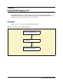
Part No. P0609711 01.01
May 4, 2004
Business Communications
Manager
BCM Imaging Tool User Guide
2
Copyright © 2004 Nortel Networks
All rights reserved. May 4, 2004.
The information in this document is subject to change without notice. The statements, configurations, technical data, and
recommendations in this document are believed to be accurate and reliable, but are presented without express or implied
warranty. Users must take full responsibility for their applications of any products specified in this document. The
information in this document is proprietary to Nortel Networks NA Inc.
Trademarks
NORTEL NETWORKS is a trademark of Nortel Networks.
Microsoft, MS, MS-DOS, Windows, and Windows NT are registered trademarks of Microsoft Corporation.
All other trademarks and registered trademarks are the property of their respective owners.
P0609711 01.01
3
Contents
Figures . . . . . . . . . . . . . . . . . . . . . . . . . . . . . . . . . . . . . . . . . . . . . . . . . . . . . . . . . . . 5
Preface . . . . . . . . . . . . . . . . . . . . . . . . . . . . . . . . . . . . . . . . . . . . . . . . . . . . . . . . . . . 7
Symbols used in this guide . . . . . . . . . . . . . . . . . . . . . . . . . . . . . . . . . . . . . . . . . . . . . . . . . . . 7
Text conventions . . . . . . . . . . . . . . . . . . . . . . . . . . . . . . . . . . . . . . . . . . . . . . . . . . . . . . . . . . . 7
Acronyms . . . . . . . . . . . . . . . . . . . . . . . . . . . . . . . . . . . . . . . . . . . . . . . . . . . . . . . . . . . . . . . . . 8
Related publications . . . . . . . . . . . . . . . . . . . . . . . . . . . . . . . . . . . . . . . . . . . . . . . . . . . . . . . . 8
How to get help . . . . . . . . . . . . . . . . . . . . . . . . . . . . . . . . . . . . . . . . . . . . . . . . . . . . . . . . . . . . 9
USA and Canada . . . . . . . . . . . . . . . . . . . . . . . . . . . . . . . . . . . . . . . . . . . . . . . . . . . . . . . . 9
Presales Support (CSAN) . . . . . . . . . . . . . . . . . . . . . . . . . . . . . . . . . . . . . . . . . . . . . . . . . 9
EMEA (Europe, Middle East, Africa) . . . . . . . . . . . . . . . . . . . . . . . . . . . . . . . . . . . . . . . . . 9
CALA (Caribbean & Latin America) . . . . . . . . . . . . . . . . . . . . . . . . . . . . . . . . . . . . . . . . . . 9
APAC (Asia Pacific) . . . . . . . . . . . . . . . . . . . . . . . . . . . . . . . . . . . . . . . . . . . . . . . . . . . . . . 9
Chapter 1
Using BCM Imaging Tool . . . . . . . . . . . . . . . . . . . . . . . . . . . . . . . . . . . . . . . . . . . . 11
Overview . . . . . . . . . . . . . . . . . . . . . . . . . . . . . . . . . . . . . . . . . . . . . . . . . . . . . . . . . . . . . . . . 11
Prerequisites . . . . . . . . . . . . . . . . . . . . . . . . . . . . . . . . . . . . . . . . . . . . . . . . . . . . . . . . . . 12
Compatible USB CD-ROM drives . . . . . . . . . . . . . . . . . . . . . . . . . . . . . . . . . . . . . . . 12
Connecting to the Business Communications Manager . . . . . . . . . . . . . . . . . . . . . . . . . . . . 13
Disconnecting power from the Business Communications Manager . . . . . . . . . . . . . . . 13
Connecting a monitor and keyboard . . . . . . . . . . . . . . . . . . . . . . . . . . . . . . . . . . . . . . . . 14
Connecting a monitor and keyboard to a BCM 1000 . . . . . . . . . . . . . . . . . . . . . . . . 14
Connecting a monitor and keyboard to a BCM 200 or BCM 400 . . . . . . . . . . . . . . . 14
Connecting a CD-ROM drive to the Business Communications Manager . . . . . . . . . . . 16
Connecting a USB CD-ROM drive to a BCM 200 or BCM 400 . . . . . . . . . . . . . . . . 17
Connecting an IDE CD-ROM drive to a BCM 200 or BCM 400 . . . . . . . . . . . . . . . . 17
Connecting an IDE CD-ROM drive to a BCM 1000 . . . . . . . . . . . . . . . . . . . . . . . . . 17
Connecting a network cable to the Business Communications Manager . . . . . . . . . . . . 18
Loading the BCM Image . . . . . . . . . . . . . . . . . . . . . . . . . . . . . . . . . . . . . . . . . . . . . . . . . . . . 19
Loading the BCM Image from a CD-ROM drive . . . . . . . . . . . . . . . . . . . . . . . . . . . . . . . 20
Loading the BCM Image from a network drive . . . . . . . . . . . . . . . . . . . . . . . . . . . . . . . . 23
Preparing a shared network drive . . . . . . . . . . . . . . . . . . . . . . . . . . . . . . . . . . . . . . . 28
Configuring your computer to connect using an Ethernet crossover cable . . . . . . . 28
Returning the Business Communications Manager to normal operation . . . . . . . . . . . . . . . 29
Removing a USB CD-ROM drive from a BCM 200 or BCM 400 . . . . . . . . . . . . . . . . . . . 30
Removing an IDE CD-ROM drive from a BCM 200 or BCM 400 . . . . . . . . . . . . . . . . . . 30
Removing an IDE CD-ROM drive from a BCM 1000 . . . . . . . . . . . . . . . . . . . . . . . . . . . 30
Disconnecting the monitor and keyboard from a BCM 1000 . . . . . . . . . . . . . . . . . . . . . . 31
Disconnecting the monitor and keyboard from a BCM 200 or BCM 400 . . . . . . . . . . . . . 31
BCM Imaging Tool User Guide
4
Contents
Restarting the Business Communications Manager . . . . . . . . . . . . . . . . . . . . . . . . . . . . 33
Initializing the Business Communications Manager hard disk . . . . . . . . . . . . . . . . . . . . 33
Restoring the Business Communications Manager programming . . . . . . . . . . . . . . . . . 34
Restoring the Business Communications Manager programming using BRU . . . . . 34
Restoring the Business Communications Manager programming manually . . . . . . 34
Glossary . . . . . . . . . . . . . . . . . . . . . . . . . . . . . . . . . . . . . . . . . . . . . . . . . . . . . . . . . 35
Index . . . . . . . . . . . . . . . . . . . . . . . . . . . . . . . . . . . . . . . . . . . . . . . . . . . . . . . . . . . . 37
P0609711 01.01
5
Figures
Figure 1
Overview of using the BCM Imaging Tool . . . . . . . . . . . . . . . . . . . . . . . . . . . . . 11
Figure 2
Overview of connecting the required equipment to the Business
Communications Manager
13
Figure 3
Location of the ports on a BCM 1000 . . . . . . . . . . . . . . . . . . . . . . . . . . . . . . . . 14
Figure 4
Remove the base function tray bezel . . . . . . . . . . . . . . . . . . . . . . . . . . . . . . . . . 15
Figure 5
Location of the ports on a BCM 200 . . . . . . . . . . . . . . . . . . . . . . . . . . . . . . . . . 15
Figure 6
Location of the ports on a BCM 400 . . . . . . . . . . . . . . . . . . . . . . . . . . . . . . . . . 16
Figure 7
Overview of returning the Business Communications Manager to its normal
configuration
Figure 8
Install the base function tray bezel . . . . . . . . . . . . . . . . . . . . . . . . . . . . . . . . . . . 31
Figure 9
Install the base function tray . . . . . . . . . . . . . . . . . . . . . . . . . . . . . . . . . . . . . . . . 32
29
BCM Imaging Tool User Guide
6
Figures
P0609711 01.01
7
Preface
The BCM Imaging Tool is a tool intended to correct configuration or hard disk content problems
that cannot be solved using other methods. The BCM Imaging Tool allows you to change the
contents of the Business Communications Manager hard drive back to its factory settings.
This guide provides information about how to use the BCM Imaging Tool.
Symbols used in this guide
This guide uses symbols to draw your attention to important information. The following symbols
appear in this guide:
Caution: Caution Symbol
Alerts you to conditions where you can damage the equipment.
Danger: Electrical Shock Hazard Symbol
Alerts you to conditions where you can get an electrical shock.
Warning: Warning Symbol
Alerts you to conditions where you can cause the system to fail or work improperly.
Note: Note Symbol
A Note alerts you to important information.
!
Security note: This symbol indicates a point of system security where a default should
be changed, or where the administrator needs to make a decision about the level of
security required for the system.
Text conventions
This guide uses the following text conventions:
italic text
Indicates book titles.
Example: Business Communications Manager Installation and
Maintenance Guide.
bold text
Indicates items on the screen or keys on the keyboard.
Example: Press the Enter key.
BCM Imaging Tool User Guide
8
Acronyms
Acronyms
This guide uses the following acronyms:
BRU
Backup and Restore Utility
DHCP
Dynamic Host Configuration Protocol
IDE
Integrated Device Electronics
IP
Internet Protocol
LAN
Local Area Network
PC
Personal Computer
USB
Universal Serial Bus
WAN
Wide Area Network
WINS
Windows Internet Name Service
Related publications
For more information about using Business Communications Manager, refer to the following
publications:
•
•
•
•
Programming Operations Guide
This document provides information about configuring the Business Communications
Manager.
Management User Guide
This document provides information about managing the Business Communications Manager,
including how to use the Backup and Restore Utility (BRU).
Software Keycode Installation Guide
This document provides information about obtaining and adding software keycodes to the
Business Communications Manager system.
Installation and Maintenance Guide
This document provides information about installing and maintaining a Business
Communications Manager system.
P0609711 01.01
How to get help
9
How to get help
USA and Canada
Authorized Distributors - ITAS Technical Support
Telephone:
1-800-4NORTEL (1-800-466-7835)
If you already have a PIN Code, you can enter Express Routing Code (ERC) 196#.
If you do not yet have a PIN Code, or for general questions and first line support, you can enter
ERC 338#.
Website:
http://www.nortelnetworks.com/support
Presales Support (CSAN)
Telephone:
1-800-4NORTEL (1-800-466-7835)
Use Express Routing Code (ERC) 1063#
EMEA (Europe, Middle East, Africa)
Technical Support - CTAS
Telephone:
* European Freephone
European Alternative/
United Kingdom
Africa
Israel
00800 800 89009
+44 (0)870-907-9009
+27-11-808-4000
800-945-9779
* Note: Calls are not free from all countries in Europe, Middle East or Africa
Fax:
44-191-555-7980
email:
[email protected]
CALA (Caribbean & Latin America)
Technical Support - CTAS
Telephone: 1-954-858-7777
email: [email protected]
APAC (Asia Pacific)
Technical Support - CTAS
Telephone: +61 388664627
Fax: +61 388664644
email: [email protected]
BCM Imaging Tool User Guide
10
How to get help
P0609711 01.01
11
Chapter 1
Using BCM Imaging Tool
The BCM Imaging Tool is a software application you use if the contents of the Business
Communications Manager hard drive becomes corrupted. With the BCM Imaging Tool you can
change the contents of the hard drive back to factory default.
Overview
Figure 1 shows an overview of using the BCM Imaging Tool.
Figure 1 Overview of using the BCM Imaging Tool
Connect the equipment to the
Business Communications Manager.
Load the image.
Return the Business Communications
Manager to normal operation.
BCM Imaging Tool User Guide
12
Overview
Prerequisites
To use the BCM Imaging Tool, you must be at the same site as the Business Communications
Manager system. You also need the following:
•
•
•
•
•
•
•
a BCM Imaging Tool CD
This CD contains the BCM Imaging Tool application and the system files required by the
Business Communications Manager system to boot from this CD.
a set of BCM Image CDs
This set of CDs contains the files that are being loaded onto the Business Communications
Manager system. There is one set of BCM Image CDs for each version of Business
Communications Manager software that you can load. Make sure you have the correct set of
CDs for the Business Communications Manager software version you want to load (for
example, BCM 3.6).
an access code for the Business Communications Manager system you are working on
a keyboard
a monitor
a USB or IDE CD-ROM drive
access to a network drive (optional)
Note: The BCM Imaging Tool does not work on Business Communications Manager
systems with an 8 GB hard drive.
Note: To use a USB CD-ROM drive, your Business Communications Manager system
must be a BCM 200 or BCM 400. As well, your system have been purchased with
software version 3.5 or greater, or upgraded to software version 3.5 or greater using the
Business Communications Manager Upgrade Kit.
Compatible USB CD-ROM drives
The BCM Imaging Tool works with USB CD-ROM drives that support the El Torito Bootable
CD-ROM Format Specification. The following USB CD-ROM drives have been tested by Nortel
Networks and are known to be compatible with the BCM Imaging Tool.
•
•
•
•
•
PlexWriter™ 24/10/24U Hi-Speed USB external CD-RW drive
LG Portable USB 2.0 CD-RW/DVD-ROM Drive
Iomega CD-RW 52x24x52x USB 2.0 Drive
Universal BUSlink USB 2.0 SLIM 24X CD-ROM PC
Addronics 52x32x32x
Other USB CD-ROM drives may be compatible, but they have not been tested by Nortel Networks
for compatibility.
P0609711 01.01
Connecting to the Business Communications Manager
13
Connecting to the Business Communications Manager
To use the BCM Imaging Tool, you must connect a monitor, keyboard and CD-ROM drive to the
Business Communications Manager. Figure 2 shows the high level steps required to connect this
equipment to the Business Communications Manager.
Figure 2 Overview of connecting the required equipment to the Business Communications Manager
Disconnect power.
Connect the monitor and keyboard.
Connect the CD-ROM drive.
Connect a network cable, if applicable.
Disconnecting power from the Business Communications Manager
1
If you still have access to the Unified Manager, shut down the system using the Shutdown
command.
2
Remove all of the data and telephony connections from the front of the Business
Communications Manager.
3
Disconnect the Business Communications Manager from the AC power outlet.
BCM Imaging Tool User Guide
14
Connecting to the Business Communications Manager
Connecting a monitor and keyboard
To use the BCM Imaging Tool, you must connect a monitor and keyboard to the Business
Communications Manager. The monitor and keyboard are connected to ports on the front of the
Business Communications Manager.
Connecting a monitor and keyboard to a BCM 1000
1
Open the door on the bezel to reveal the ports.
2
Connect the monitor and keyboard to the appropriate port. Refer to Figure 3 for the location of
the ports.
Figure 3 Location of the ports on a BCM 1000
keyboard port
monitor port
Connecting a monitor and keyboard to a BCM 200 or BCM 400
1
Attach one end of a grounding strap to your wrist and the other end to a grounded metal
surface.
2
Remove the base function tray latch screws. Place the screws in a safe location.
3
Move the base function tray latches to the unlocked position. See Figure 4.
4
Grasp the base function tray latches and partially remove the base function tray from the
platform base chassis. Do not exert force on the DS30 ribbon cables or connectors.
5
Unfasten the bezel screws from the base function tray face. Place the screws in a safe location.
6
Pull and tip the bezel away from the base function tray until the bezel clips are clear of the
base function tray chassis. Move the bezel in a downward direction between the base function
tray latches. Place the bezel in a safe location.
P0609711 01.01
Connecting to the Business Communications Manager
15
Figure 4 Remove the base function tray bezel
Bezel
1
2
Tip bezel away
from base
function tray
Unfasten
Bezel screws
3
4
Move bezel downward
and between latches
Unhook bezel clips
from base function
tray chassis
7
Push the base function tray completely into the chassis. Be careful not to crimp the DS30
ribbon cables.
8
Move the base function tray latches to the locked position.
9
Connect the monitor and keyboard to the appropriate ports. Refer to Figure 5 or Figure 6 for
the locations of these ports.
Figure 5 Location of the ports on a BCM 200
keyboard port
monitor port
USB ports
BCM Imaging Tool User Guide
16
Connecting to the Business Communications Manager
Figure 6 Location of the ports on a BCM 400
Primary Mirror
keyboard port
Master
Buzzer Off
monitor port
USB ports
Connecting a CD-ROM drive to the Business Communications
Manager
To use the BCM Imaging Tool, you must connect a CD-ROM drive to the Business
Communications Manager. The Business Communications Manager system uses this CD-ROM
drive as the boot device when you start the BCM Imaging Tool and to load the information from
the BCM Image CDs.
If your Business Communications Manager system is a BCM 200 or a BCM 400, you can use a
USB CD-ROM drive or an IDE CD-ROM drive. The advantage of the USB CD-ROM drive is that
it is quicker and easier to install on the Business Communications Manager. The advantage of the
IDE CD-ROM drive is that it loads the BCM Image much quicker.
Note: To use a USB CD-ROM drive with a BCM 200 or a BCM 400, your Business
Communications Manager system must be using software version 3.5 or greater.
Tip: To get the benefits of easier CD-ROM drive installation and faster loading of the
BCM Image, use a USB CD-ROM drive and load the BCM Image from a shared network
drive.
If your Business Communications Manager system is a BCM 1000, you must use an IDE
CD-ROM drive.
P0609711 01.01
Connecting to the Business Communications Manager
17
Connecting a USB CD-ROM drive to a BCM 200 or BCM 400
1
Place the CD-ROM drive next to the Business Communications Manager.
2
Connect the USB cable from the CD-ROM drive to one of the USB ports on the front of the
BCM 200 or BCM 400. For the location of the USB ports, refer to Figure 5 for the BCM 200
or Figure 6 for the BCM 400.
3
Connect the power cable to the CD-ROM drive.
Connecting an IDE CD-ROM drive to a BCM 200 or BCM 400
1
Make sure that power is disconnected from the BCM 200 or BCM 400. If it is not, refer to
“Disconnecting power from the Business Communications Manager” on page 13.
2
If required for accessibility, remove the BCM 200 or BCM 400 from the rack, or the wall, and
place it on a flat, clean and static-free surface.
3
Attach one end of a grounding strap to your wrist and the other end to a grounded metal
surface.
4
Remove the top cover screws located at the rear of the BCM 200 or BCM 400. Place the
screws in a safe location.
5
Lift the back of the cover and slide it rear-ward until it disengages from the BCM 200 or
BCM 400.
6
Lift the top cover up and away from the BCM 200 or BCM 400. Place the cover in a safe
location.
7
Place the CD-ROM drive in the BCM 200 or BCM 400.
Make sure you leave room in front of the CD-ROM drive to allow inserting the CDs.
8
Connect the available connector on the IDE cable to the CD-ROM drive.
9
Connect an available power connector to the back of the CD-ROM drive.
Connecting an IDE CD-ROM drive to a BCM 1000
1
Make sure that power is disconnected from the BCM 1000. If it is not, refer to “Disconnecting
power from the Business Communications Manager” on page 13.
2
Attach one end of a grounding strap to your wrist and the other end to a grounded metal
surface.
3
If required for accessibility, remove the BCM 1000 from the rack, or the wall, and place it on a
flat, clean and static-free surface.
4
Remove the two screws from the cover, at the back of the BCM 1000.
5
Lift the back of the cover and slide it back and up.
6
Place the CD-ROM drive in the BCM 1000.
Make sure you leave room in front of the CD-ROM drive to allow inserting the CDs.
7
Connect the available connector on the IDE cable to the CD-ROM drive.
8
Connect an available power connector to the back of the CD-ROM drive.
BCM Imaging Tool User Guide
18
Connecting to the Business Communications Manager
Connecting a network cable to the Business Communications
Manager
When you are loading a BCM Image to the hard drive, you can load the BCM Image from the
CD-ROM drive connected to the Business Communications Manager system, a shared network
drive or a shared CD-ROM drive. To use a shared network drive or a shared CD-ROM drive, you
must connect the Business Communications Manager to a computer on the network or to a local
computer.
To connect the Business Communications Manager to a computer on the network, use a standard
Ethernet cable to connect the LAN card on the Business Communications Manager to a port of a
switch or router on the network.
To connect the Business Communications Manager to a local computer:
•
Use an Ethernet cross-over cable to connect the LAN card on the Business Communications
Manager to the LAN card on the local computer.
or
•
Use a standard Ethernet cable to connect the LAN card on the Business Communications
Manager to a port on a local hub or switch. Use a second Ethernet cable to connect the LAN
card on the local computer to another port on the local hub or switch.
P0609711 01.01
Loading the BCM Image
19
Loading the BCM Image
The BCM Image is a copy of the contents of the Business Communications Manager hard drive as
it was when it was shipped from the factory. You load the BCM Image when you want to change
the Business Communications Manager applications and settings back to their factory defaults.
Two examples of when you might load the BCM Image are:
•
•
if there has been a serious configuration error that does not allow the Business
Communications Manager to start up
the Business Communications Manager system has been returned from a lease customer and
you want to reset it to factory condition
Warning: Loading the BCM Image erases all of the information that has been stored on
the Business Communications Manager hard drive. This includes keycodes, application
patches, configuration programming, voice messages, and greetings.
Note that telephony programming is not stored on the hard drive and therefore is not
erased when you load a BCM image. If you want to erase the telephony programming, you
must perform a system startup. For information about how to perform a system startup,
refer to “Performing a system startup and warm reset” in the Business Communications
Manager Management User Guide.
When you are loading the BCM Image, you can load one of the following software versions as
well as any software version greater than BCM 3.6:
•
•
•
•
BCM 3.0
BCM 3.0.1
BCM 3.5
BCM 3.6
You can load the BCM Image from the CD-ROM drive connected to the Business
Communications Manager, from a shared network drive or from a shared CD-ROM drive.
Note: If you want to use the Backup and Restore Utility (BRU) to restore the system
programming, you must load the BCM Image for the same software version that the
backup was made with (i.e. the same version that is currently on your Business
Communications Manager).
Nortel Networks recommends that you load the same software version that is currently on
the Business Communications Manager system.
If you would like to change the software version, use the Business Communications
Manager Upgrade Kit after you have finished loading the BCM Image. The Upgrade Kit
includes additional updates that are not loaded when you use the BCM Imaging Tool.
For example, the Upgrade Kit for software version 3.5 includes a BIOS update that
enables USB support. If you used the BCM Imaging Tool to change the software version
from 3.01 to 3.5, the Business Communications Manager system would not get the update
required to support USB CD-ROM drives.
BCM Imaging Tool User Guide
20
Loading the BCM Image
Loading the BCM Image from a CD-ROM drive
To load the BCM Image from a CD-ROM drive, you must have a CD-ROM drive connected to the
Business Communications Manager system.
Tip: Loading the BCM Image from an IDE CD-ROM drive is much faster than loading the
BCM Image from a USB CD-ROM drive.
If you connected a USB CD-ROM drive to the Business Communications Manager, load
the BCM image using a shared network drive whenever possible. Loading the BCM Image
from a shared network drive significantly reduces the amount of time it takes to load the
BCM Image. (Loading from a USB CD-ROM drive takes approximately 65 minutes,
while loading from a shared drive or IDE CD-ROM drive takes approximately 15
minutes.)
1
Connect the required equipment to the Business Communications Manager. For information
about how to connect the equipment, refer to “Connecting to the Business Communications
Manager” on page 13.
2
Turn on the monitor connected to the Business Communications Manager.
3
If you are using a USB CD-ROM drive, turn on the CD-ROM drive power switch.
If you are using an IDE CD-ROM drive, connect power to the Business Communications
Manager to power up the CD-ROM drive.
4
Load the BCM Imaging Tool CD into the CD-ROM drive connected to the Business
Communications Manager.
5
If you are using a USB CD-ROM drive, connect power to the Business Communications
Manager.
If you are using an IDE CD-ROM drive, reboot the Business Communications Manager by
disconnecting power from the Business Communications Manager and then reconnecting
power.
The Startup Menu appears.
6
Select the CD-ROM drive in which you installed the BCM Imaging Tool CD and press the
Enter key.
The License Agreement screen appears.
7
Read the entire License Agreement and press the Enter key.
To scroll the License Agreement up or down, use the Page Up, Page Down or arrow keys.
P0609711 01.01
Loading the BCM Image
8
21
If you want to accept the License Agreement and use the BCM Imaging Tool, use the Tab key
to highlight the Accept button and press the Enter key.
The Unlock screen appears.
Note: If you do not want to accept the License Agreement, use the Tab key to
highlight the Decline button and press the Enter key. The BCM Imaging Tool exits.
9
Enter the Access Code for this Business Communications Manager system.
If you do not have the Access Code for this Business Communications Manager system,
contact your Nortel Networks support personnel and request the Access Code for this system.
Provide the support personnel with the Unique ID that is shown on Unlock screen of the BCM
Imaging Tool.
Note: An Access Code works for only one Business Communications Manager
system. You cannot use an Access Code from another Business Communications
Manager system.
10 Use the Tab key to highlight the OK button and press the Enter key (or press Alt+O).
The Select Media Location screen appears.
11 Use the Tab key to select the Local CD-ROM option and then press the Space bar.
BCM Imaging Tool User Guide
22
Loading the BCM Image
12 Use the Tab key to highlight the OK button and press the Enter key (or press Alt+O).
Follow the instructions on the screen to continue. Make sure you have the BCM Image CDs
ready to insert when requested by the BCM Imaging Tool.
Note: After you insert a CD in the CD-ROM drive, wait at least 5 seconds before you
press the Enter key. This allows the CD-ROM drive time to recognize the new CD.
If you press Enter before the CD-ROM drive is ready, you will receive an error
message. Leave the CD in the CD-ROM drive, wait at least 5 seconds and then press
the Enter button. If the error message gives you the option of Abort or Retry, press the
R button.
13 Use the Tab key to highlight the OK button and press the Enter key (or press Alt+O).
The Image File Needed screen appears.
14 Insert the first BCM Image CD into the CD-ROM drive.
A Warning screen appears.
15 Press the Enter key and follow the instructions on the screen to continue.
16 Use the Tab key to highlight the Yes button and press the Enter key (or press Alt+Y).
17 When the BCM Imaging Tool has finished loading the BCM Image, the BCM Imaging
Completed screen appears. You can now return the Business Communications Manager
system to its normal operating configuration using the steps in “Returning the Business
Communications Manager to normal operation” on page 29.
P0609711 01.01
Loading the BCM Image
23
Loading the BCM Image from a network drive
To load the BCM Image from a network drive, you must have a CD-ROM drive connected to the
Business Communications Manager system. You must also have one of the following network
connections.
•
•
A computer connected to the Business Communications Manager system using an Ethernet
crossover cable or two Ethernet cables and a local hub or switch. For information about the
network settings required for this connection, refer to “Configuring your computer to connect
using an Ethernet crossover cable” on page 28.
A computer on the network that you can access from the Business Communications Manager
system.
Note: The computer that has the network drive you want to use must be using
Windows NT, Windows 2000 or Windows XP. The BCM Imaging Tool does not
support Windows 95, Windows 98 or Windows Me.
The network share can be a shared folder on a hard drive or a shared CD-ROM drive. If you are
using a shared folder on a hard drive, you must load the BCM Imaging Tool and the BCM Images
onto the shared folder before you start the BCM Imaging Tool. For information about loading
these files onto a shared folder, refer to “Preparing a shared network drive” on page 28. If you are
using a shared CD-ROM drive, load the BCM Image CDs into the shared CD-ROM drive when
requested by the BCM Imaging Tool.
To load the BCM Image:
1
Connect the required equipment to the Business Communications Manager. For information
about how to connect the equipment, refer to “Connecting to the Business Communications
Manager” on page 13.
2
Turn on the monitor connected to the Business Communications Manager.
3
If you are using a USB CD-ROM drive, turn on the CD-ROM drive power switch.
If you are using an IDE CD-ROM drive, connect power to the Business Communications
Manager to power up the CD-ROM drive.
4
Load the BCM Imaging Tool CD into the CD-ROM drive connected to the Business
Communications Manager.
5
If you are using a USB CD-ROM drive, connect power to the Business Communications
Manager.
If you are using an IDE CD-ROM drive, reboot the Business Communications Manager by
disconnecting power from the Business Communications Manager and then reconnecting
power.
The Startup Menu appears.
BCM Imaging Tool User Guide
24
Loading the BCM Image
6
Select the CD-ROM drive in which you installed the BCM Imaging Tool CD and press the
Enter key.
The License Agreement screen appears.
7
Read the entire License Agreement and press the Enter key.
To scroll the License Agreement up or down, use the Page Up, Page Down or arrow keys.
8
If you want to accept the License Agreement and use the BCM Imaging Tool, use the Tab key
to highlight the Accept button and press the Enter key.
The Unlock screen appears.
Note: If you do not want to accept the License Agreement, use the Tab key to
highlight the Decline button and press the Enter key. The BCM Imaging Tool exits.
9
Enter the Access Code for this Business Communications Manager system.
If you do not have the Access Code for this Business Communications Manager system,
contact your Nortel Networks support personnel and request the Access Code for this system.
Provide the support personnel with the Unique ID that is shown on Unlock screen of the BCM
Imaging Tool.
Note: An Access Code works for only one Business Communications Manager
system. You cannot use an Access Code from another Business Communications
Manager system.
10 Use the Tab key to highlight the OK button and press the Enter key (or press Alt+O).
The Select Media Location screen appears.
P0609711 01.01
Loading the BCM Image
25
11 Use the Tab key to select the Network Share option and then press the Space bar.
12 Use the Tab key to highlight the OK button and press the Enter key (or press Alt+O).
The Select Network Type screen appears.
13 If your network uses DHCP, use the Tab key to highlight the OK button and press the Enter
key (or press Alt+O). Proceed to Step 20.
If you are using a local computer or your networks does not use DHCP, use the Tab key to
select the Static IP option and then press the Space bar.
14 Use the Tab key to highlight the OK button and press the Enter key (or press Alt+O).
The Enter Network IP Info screen appears.
15 Enter the IP address of the Business Communications Manager system and press the Tab key.
The Subnet field is highlighted.
16 Enter the Subnet mask of the Business Communications Manager and press the Tab key.
The Gateway field is highlighted.
17 If the computer with the shared drive is on a different subnet, enter the IP address of gateway
for the network to which the Business Communications Manager is connected and press the
Tab key.
If the computer with the shared drive is on the same subnet, press the Tab key.
The WINS field is highlighted.
18 If the network uses a WINS server, enter the IP address of the WINS server.
If the network does not use a WINS server, go to the next step.
BCM Imaging Tool User Guide
26
Loading the BCM Image
19 Use the Tab key to highlight the OK button and press the Enter key (or press Alt+O).
The Windows Networking Logon screen appears.
20 Enter the name of the Domain in which the computer with the shared drive is located and press
the Tab key.
If you are not using domain names on your network, enter the Machine Name of the computer
with the shared drive or the name of the Workgroup to which the computer belongs and press
the Tab key.
The Userid field is highlighted.
21 Enter the User name required to access the shared drive and press the Tab key.
The Password field is highlighted.
22 Enter the Password required to access the shared drive.
23 Use the Tab key to highlight the OK button and press the Enter key (or press Alt+O).
The Image Storage screen appears.
24 Enter the pathname of the shared drive (for example, \\rdoe-3\BIT35).
Note: You cannot use an IP address in the pathname you enter to specify the location
of the shared drive. You must always use the server name.
25 Use the Tab key to highlight the OK button and press the Enter key (or press Alt+O).
If there is only one BCM Image on the shared drive, a Verification screen appears. Go to
Step 27.
If there is more than one BCM image on the shared drive, the Image Selection screen appears.
Continue with Step 26.
26 Use the Tab key to select the image file you want to load and press the Enter key.
A Verification screen appears.
P0609711 01.01
Loading the BCM Image
27
27 Use the Tab key to highlight the Yes button and press the Enter key (or press Alt+Y).
Note: If you are using a shared CD-ROM drive, you must insert the BCM Imaging
Tool CD and the BCM Image CDs in the shared CD-ROM drive when prompted by
the BCM Imaging Tool.
28 When the BCM Imaging Tool has finished loading the BCM Image, the BCM Imaging
Completed screen appears. You can now return the Business Communications Manager
system to its normal operating configuration using the steps in “Returning the Business
Communications Manager to normal operation” on page 29.
BCM Imaging Tool User Guide
28
Loading the BCM Image
Preparing a shared network drive
If you are loading the BCM Image from a shared network drive, you must load the contents of the
BCM Imaging Tool CD and the BCM Image CDs onto the network drive before you start. To
prepare the network drive:
1
Create a folder on the computer you want to use for sharing.
2
Enable sharing on the folder and set the permissions so that the Business Communications
Manager can access this folder. For information about how to enable sharing or set the
permissions, refer to the documentation for your computer.
3
Copy the contents of the BCM Imaging Tool CD into the shared folder.
Make sure the contents of the BCM Imaging Tool CD are at the top level of the folder.
4
Copy the contents of BCM Image CDs into the shared folder.
Make sure the contents of all of the BCM Image CDs are at the top level of the folder.
5
Repeat step 4 for each version of the BCM Image CDs you want to load.
Configuring your computer to connect using an Ethernet crossover cable
When you are connecting your computer to the Business Communications Manager using an
Ethernet crossover cable, or a local hub or switch, you must change the network settings on your
computer. The table below shows the recommended settings for this type of connection.
Network settings on your
computer
Value
BCM Imaging Tool setting
Value
Select Network Type
Static IP
IP Address
10.10.10.100
IP
10.10.10.1
Subnet mask
255.255.255.0
Subnet
255.255.255.0
Default Gateway
10.10.10.100
Gateway
10.10.10.100
For information about how to set the network parameters on your computer, refer to your
Operating System documentation.
Note: Make sure you record your current network setting, so you can change them back
when you are finished using the BCM Imaging Tool.
P0609711 01.01
Returning the Business Communications Manager to normal operation
29
Returning the Business Communications Manager to normal
operation
After you have finished applying a BCM Image, you must return the Business Communications
Manager system to its normal operating configuration. Figure 7 shows the high level steps required
to return the Business Communications Manager to its normal configuration.
Figure 7 Overview of returning the Business Communications Manager to its normal configuration
Remove the CD-ROM drive.
Disconnect the monitor and keyboard.
Restart the Business
Communications Manager.
Initialize the hard disk.
Restore the system programming.
BCM Imaging Tool User Guide
30
Returning the Business Communications Manager to normal operation
Removing a USB CD-ROM drive from a BCM 200 or BCM 400
1
Turn off the CD-ROM drive.
2
Disconnect the power cable from the CD-ROM drive.
3
Disconnect the USB cable from the CD-ROM drive and the Business Communications
Manager.
Removing an IDE CD-ROM drive from a BCM 200 or BCM 400
1
Disconnect the power cable from the BCM 200 or BCM 400.
2
Attach one end of a grounding strap to your wrist and the other end to a grounded metal
surface.
3
Disconnect the IDE ribbon cable from the CD-ROM drive.
4
Disconnect the power connector from the CD-ROM drive.
5
Remove the CD-ROM drive from the BCM 200 or BCM 400.
6
Set the top cover on the BCM 200 or BCM 400.
7
With the rear of top cover slightly raised, slide the top cover forward until the cover engages
with the BCM 200 or BCM 400.
8
Press the top cover down until it rests on the BCM 200 or BCM 400.
9
Install the two top cover screws at the rear of the platform base chassis.
Removing an IDE CD-ROM drive from a BCM 1000
1
Disconnect the power cable from the BCM 1000.
2
Attach one end of a grounding strap to your wrist and the other end to a grounded metal
surface.
3
Disconnect the IDE ribbon cable from the CD-ROM drive.
4
Disconnect the power connector from the CD-ROM drive.
5
Remove the CD-ROM drive from the BCM 1000.
6
Set the top cover on the BCM 1000.
7
With the rear of top cover slightly raised, slide the top cover forward until the cover engages
with the BCM 1000.
8
Press the top cover down until it rests on the BCM 1000.
9
Install the two top cover screws at the rear of the platform base chassis.
P0609711 01.01
Returning the Business Communications Manager to normal operation
31
Disconnecting the monitor and keyboard from a BCM 1000
To disconnect the monitor and keyboard:
1
Remove the monitor and keyboard cables from the Business Communications Manager.
2
Close the door on the bezel.
Disconnecting the monitor and keyboard from a BCM 200 or
BCM 400
To disconnect the monitor and keyboard:
1
Make sure the Business Communications Manager is disconnected from the AC power outlet.
2
Attach one end of a grounding strap to your wrist and the other end to a grounded metal
surface.
3
Disconnect the monitor and keyboard cables from the BCM 200 or BCM 400.
4
Move the base function tray latches to the unlocked position.
5
Position the bezel below and between the base function tray latches. Lift the bezel until the
bezel clips line-up with the corresponding base function tray bezel holes.
6
Tilt the bezel forward, then push the bottom of the bezel into the base function tray chassis to
engage the bezel clips.
7
Push on the face of the bezel so that it rests flush with the face of the base function tray
chassis.
8
Install the base function tray bezel screws. See Figure 8.
Figure 8 Install the base function tray bezel
3
4
Push bezel against
base function tray
Install Bezel
screws
2
1
Position bezel
between latches and
move upward
Insert bezel clips
into base function
tray chassis
BCM Imaging Tool User Guide
32
Returning the Business Communications Manager to normal operation
9
Push the base function tray completely into the chassis. Be careful not to crimp the DS30
ribbon cables.
10 Move the base function tray latches to the locked position. Refer to Figure 9.
11 Install the base function tray latch screws.
Figure 9 Install the base function tray
2
Connect DS30 cables
to the MSC
3
Insert base function tray completely.
Move base function tray latches to
the locked position
1
Slide base function tray
partially into the platform
base chassis
4
Fasten base function
tray latch screws
P0609711 01.01
Returning the Business Communications Manager to normal operation
33
Restarting the Business Communications Manager
1
If you removed the Business Communications Manager from the rack or wall, replace it.
2
Plug the Business Communications Manager and the expansion unit, if there is one, into the
AC power source.
The Business Communications Manager automatically starts booting.
The reboot can take several minutes to complete.
Note: Plug in the expansion unit immediately after plugging in the Business
Communications Manager to ensure synchronization between the two units.
3
Reconnect all the connectors to the front of the units.
Initializing the Business Communications Manager hard disk
After you have finished applying the BCM Image, you must initialize the hard disk. This restores
several key settings that are normally set at the factory. For information about how to initialize the
hard drive, refer to Initialize the Hard Disk in the Business Communications Manager
Installation and Maintenance Guide.
The procedure for initializing the hard disk is different on the various Business Communications
Manager software versions. For this reason, make sure you use the Installation and Maintenance
Guide for the correct Business Communications Manager model (BCM 1000, BCM 200 or
BCM 400) and software version (BCM 3.0, BCM 3.0.1, BCM 3.5, BCM 3.6 or greater).
!
Security note: If you loaded Business Communications Manager software version 3.5,
Telnet and BCM Drive Shares are enabled.
To ensure optimal security, you should disable these two settings. For information on how
to disable Telnet settings, refer to the Business Communications Manager Programming
Operations Guide. For information about how to disable the BCM Drive Shares, refer to
the Business Communications Manager Management User Guide.
BCM Imaging Tool User Guide
34
Returning the Business Communications Manager to normal operation
Restoring the Business Communications Manager programming
After you have finished initializing the hard disk, you can restore the Business Communications
Manager system programming. To restore the programming, you can use the Backup and Restore
Utility (BRU) or you can manually enter the program settings.
Restoring the Business Communications Manager programming using BRU
To restore the programming using BRU, you must have previously created a backup of the system
programming using BRU. If you do not have a backup, you must restore the programming
manually.
Note: You can use BRU only if you loaded the same Business Communications Manager
software version that the backup was made with. For example, to use a backup created on
Business Communications Manager software version 3.5, you must have loaded the BCM
Image for software version 3.5 onto the Business Communications Manager.
To restore the system programming:
1
Install any patches that are applicable for this Business Communications Manager system.
Note: Only install the patches that you know operate properly on this Business
Communications Manager system.
2
Use the Backup and Restore Utility (BRU) to restore a known working copy of system
programming. The restore also loads all of the software keycodes for the system.
For information about how to use BRU, refer to the Business Communications Manager
Management User Guide.
Note: Make sure the Registry option in the Select BCM Component(s) box is not
selected before you restore the programming.
Restoring the Business Communications Manager programming manually
1
Add all of the software keycodes that are applicable for this Business Communications
Manager system.
For information about adding keycodes, refer to the Software Keycode Installation Guide.
2
Install any patches that are applicable for this Business Communications Manager system.
Note: Only install the patches that you know operate properly on this Business
Communications Manager system.
3
Use Unified Manager to manually configure the Business Communications Manager system.
For information about how to use Unified manager, refer to the Business Communications
Manager Programming Operations Guide.
P0609711 01.01
35
Glossary
This Glossary provides terms used in the BCM Imaging Tool User Guide.
BCM Image
A copy of the contents of a Business Communications Manager hard drive as it was when
it was shipped from the factory.
IDE CD-ROM drive
A CD-ROM drive that connects to the IDE cable on a computer system. This is normally
an internal CD-ROM drive.
Unified Manager
Unified Manager is a web-based navigation tool that allows you to view and change all
operations and maintenance programming on the Business Communications Manager
system.
USB CD-ROM drive
A CD-ROM drive that connects to the USB port on a computer system. This is normally
an external CD-ROM drive.
BCM Imaging Tool User Guide
36
Glossary
P0609711 01.01
37
Index
A
Access Code 21, 24
acronyms 8
software version supported 19
C
Caution symbol 7
B
Backup and Restore Utility 34
BCM 1000
IDE CD-ROM drive, connecting 17
IDE CD-ROM drive, removing 30
keyboard, connecting 14
keyboard, disconnecting 31
monitor, connecting 14
monitor, disconnecting 31
ports, location 14
BCM 200
IDE CD-ROM drive, connecting 17
IDE CD-ROM drive, removing 30
keyboard, connecting 14
keyboard, disconnecting 31
monitor, connecting 14
monitor, disconnecting 31
ports, location 15
USB CD-ROM drive, connecting 17
USB CD-ROM drive, removing 30
BCM 400
IDE CD-ROM drive, connecting 17
IDE CD-ROM drive, removing 30
keyboard, connecting 14
keyboard, disconnecting 31
monitor, connecting 14
monitor, disconnecting 31
ports, location 16
USB CD-ROM drive, connecting 17
USB CD-ROM drive, removing 30
CD-ROM drive
connecting 16
loading BCM image from 20
Connecting
CD-ROM drive 16
equipment to Business Communications Manager 13
keyboard to BCM 1000 14
keyboard to BCM 200 14
keyboard to BCM 400 14
monitor to BCM 1000 14
monitor to BCM 200 14
monitor to BCM 400 14
network cable 18
overview of equipment 13
Conventions and symbols 7
conventions, text 7
D
Danger symbol 7
Data connections
connecting 33
disconnecting 13
DHCP 25
BCM Image
loading 19
loading from CD-ROM drive 20
loading from network drive 23
Disconnecting
data connections 13
keyboard from BCM 1000 31
keyboard from BCM 200 31
keyboard from BCM 400 31
monitor from BCM 1000 31
monitor from BCM 200 31
monitor from BCM 400 31
power 13
telephony connections 13
BCM Image CDs 12
Domain 26
BCM Imaging Tool CD 12
DS30 cables 14, 32
BCM Imaging Tool, overview 11
BCM, software versions supported 19
E
BRU 34
Ethernet cable 18, 23
Business Communications Manager
restarting 33
returning to normal operation 29
Expansion unit 33
BCM Imaging Tool User Guide
38
Index
G
N
Gateway 25
Network cable, connecting 18
Network drive, loading BCM Image 23
H
Hard disk, initializing 33
Hard drive, size restriction 12
I
IDE CD-ROM drive
connecting to BCM 1000 17
connecting to BCM 200 17
connecting to BCM 400 17
removing from BCM 1000 30
removing from BCM 200 30
removing from BCM 400 30
O
Overview
BCM Imaging Tool 11
connecting equipment 13
returning Business Communications Manager to
normal operation 29
P
Information lost 19
Ports
location on BCM 1000 14
location on BCM 200 15
location on BCM 400 16
Initializing, hard disk 33
Power, disconnecting 13
IP address 25
Prerequisites 12
Programming, restoring 34
K
Keyboard
connecting to BCM 1000 14
connecting to BCM 200 14
connecting to BCM 400 14
disconnecting from BCM 1000 31
disconnecting from BCM 200 31
disconnecting from BCM 400 31
Keycodes 19, 34
L
LAN card 18
License Agreement 21, 24
Loading BCM Image 19, 20, 23
Lost information 19
M
Monitor
connecting to BCM 1000 14
connecting to BCM 200 14
connecting to BCM 400 14
disconnecting from BCM 1000 31
disconnecting from BCM 200 31
disconnecting from BCM 400 31
Publications, related 8
R
Removing
IDE CD-ROM drive, from BCM 1000 30
IDE CD-ROM drive, from BCM 200 30
IDE CD-ROM drive, from BCM 400 30
USB CD-ROM drive, from BCM 200 30
USB CD-ROM drive, from BCM 400 30
Requirements
shared drive 23
USB CD-ROM 16
Restarting, Business Communications Manager 33
Restoring, programming 34
Restrictions, hard drive size 12
S
Shared drive, requirements 23
Software keycodes 34
Software versions supported 19
Static IP 25
Subnet mask 25
Supported software version 19
Symbols, documentation 7
P0609711 01.01
Index
39
T
Telephony connections
connecting 33
disconnecting 13
text conventions 7
tip 7
U
USB cable 17
USB CD-ROM drive
connecting to BCM 200 17
connecting to BCM 400 17
removing from BCM 200 30
removing from BCM 400 30
requirements 16
W
Warning symbol 7
WINS server 25
BCM Imaging Tool User Guide
40
Index
P0609711 01.01