1
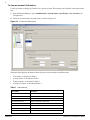
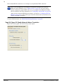
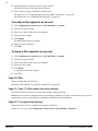
BCM 4.0
BCM 4.0
Documentation Update
Welcome to BCM 4.0, the unified communications solution that gives you an edge over your
competition.
The BCM 4.0 documentation is on the BCM 4.0 Documentation CD-ROM. This CD-ROM is
in your BCM 4.0 kit.
To view the documentation:
1
Insert the BCM 4.0 Documentation CD-ROM into the CD-ROM drive of your computer.
2
Double-click the My Computer icon.
3
Double-click the CD-ROM icon.
4
Double-click Start.pdf.
This document provides last-minute changes to the BCM 4.0 documentation.
Note:
The most recent Interactive Voice Response (IVR) docs are
available on the BCM 4.0 hard drive and Helmsman.
Updated BCM 4.0 documents
Some BCM 4.0 documents have been recently updated with new information. You can obtain
the following updated documents in the BCM 4.0 documentation collection on Helmsman
here; www.nortel.com/helmsman
•
BCM 4.0 Administration Guide
•
BCM 4.0 Device Configuration Guide
•
Multimedia Contact Center Set Up and Operation Guide
•
BCM 4.0 Networking Configuration Guide
•
SRG200/400 Release 1.5 Configuration Guide
•
WLAN IP Phone 2210/2211/2212 User Guide
•
WLAN IP Telephony Installation and Configuration Guide
BCM 4.0 Administration Guide
Page 30, BCM Element Manager
Throughout this section, references to the OAM port and craftsperson port changed to the
LAN port.
Page 254, QoS metrics
Using QoS metrics panel you can monitor QoS metrics in three ways: globally, on a perinterface basis, or on a per-account basis.
For information about how to access per-account metrics, follow the procedures in this
section. For information about accessing global or per-interface metrics, refer to the BCM 4.0
Administration Guide (N0060598).
BCM 4.0 Documentation Update
N0035913
2
To view per account QoS metrics
Use this procedure to display QoS metrics for a specific account. These metrics are available for dial-up accounts
only.
1
Open the Element Manager, select Administration > System Status > QoS Metrics > Per Account in the
navigation tree.
2
Select an account from the Accounts table, as shown in Figure 54.
Figure 54
Per Account QoS metrics
The details panel displays information about the selected account under four different tabs:
•
Total traffic, as described in Table 1
•
Average traffic, as described in Table 2
•
Totals per queue, as described in Table 3
•
Averages per queue, as described inTable 4
Table 1 Total traffic tab
Metric Name
Description
Total traffic since
Start date for collecting metrics
Total octets sent
Total Number of octets sent
Premium octets sent
Number of premium octets sent
Best effort octets sent
Number of best effort octets sent
Total packets sent
Total number of packets sent
Premium packets sent
Number of premium packets sent
Best effort packets sent
Number of best effort packets sent
Total packets within guarantee Total number of packets within the guarantee
N0035913
BCM 4.0 Documentation Update
3
Table 1 Total traffic tab
Metric Name
Description
Premium packets within
guarantee
Number of premium packets within the guarantee
Best effort packets within
guarantee
Number of best effort packets within the guarantee
Total packets over guarantee
Total number of packets over the guarantee
Premium packets over
guarantee
Number of premium packets over the guarantee
Best effort packets over
guarantee
Number of best effort packets over the guarantee
Total packets dropped
Total number of packets dropped
Premium packets dropped
Number of premium packets dropped
Best effort packets dropped
Number of best effort packets dropped
Table 2 Average traffic tab
Metric Name
Description
Average traffic from
Start date used for calculating averages
To
End date used for calculating averages
Total octets sent
Total Number of octets sent
Premium octets sent
Number of premium octets sent
Best effort octets sent
Number of best effort octets sent
Total packets sent
Total number of packets sent
Premium packets sent
Number of premium packets sent
Best effort packets sent
Number of best effort packets sent
Total packets within guarantee Total number of packets within the guarantee
Premium packets within
guarantee
Number of premium packets within the guarantee
Best effort packets within
guarantee
Number of best effort packets within the guarantee
Total packets over guarantee
Total number of packets over the guarantee
Premium packets over
guarantee
Number of premium packets over the guarantee
Best effort packets over
guarantee
Number of best effort packets over the guarantee
Total packets dropped
Total number of packets dropped
Premium packets dropped
Number of premium packets dropped
Best effort packets dropped
Number of best effort packets dropped
Table 3 Totals per queue
Metric Name
Description
Total traffic since
Start date used for calculating totals
Queue
The number of the queue
Class of query
The type of query
Octets sent
Number of octets sent
Packets sent
Number of packets sent
BCM 4.0 Documentation Update
N0035913
4
Table 3 Totals per queue
Metric Name
Description
Packets within guarantee
Number of packets within the guarantee
Packets over guarantee
Number of packets over the guarantee
Packets dropped
Number of packets dropped
Table 4 Averages per queue
Metric Name
Description
Average traffic from
Start date used for calculating averages
To
End date used for calculating averages
Queue
The number of the queue
Class of query
The type of query
Octets sent
Number of octets sent
Packets sent
Number of packets sent
Packets within guarantee
Number of packets within the guarantee
Packets over guarantee
Number of packets over the guarantee
Packets dropped
Number of packets dropped
BCM 4.0 Device Configuration Guide
Page 64, Table 19 Capabilities and preferences — IP terminal details
Delete Table 19 and insert the following text before Figure 20:
“At startup, the BCM acquires and retains a list of all IP terminals that have a registered DN. This means DNspecific features, such as Call Forward, Hotdesking, and voicemail can continue to function even if the telephone is
disconnected.
If the number of IP Set DNs registered with the BCM exceeds the number of IP Client key codes applied, selecting
this check box prioritizes a set.
For example, if the BCM is rebooted, and the number of IP phones exceeds the number of IP client key codes, the
BCM retains the DN record of the sets with this field selected, before retaining the DN record of a set that does not
have this field selected.
If Keep DN alive is not selected, and the IP telephone is disconnected, the DN record can become inactive if there
are not enough keycodes. In this case, a Not in Service prompt is produced when special features, such as Call
Forward, are invoked.
Default: Cleared
Multimedia Contact Center Set Up and Operation Guide
Page 9, How Multimedia Contact Center works for callers
Replace the content in the section How Multimedia Contact Center works for callers with the following
information:
N0035913
BCM 4.0 Documentation Update
5
When callers on a Web site click a multimedia HTML link, the Call setup page appears.
In the call setup page, callers specify their calling preferences. Callers can access the media types based on their
needs and resources. Callers with separate data and PSTN voice lines can make a PSTN voice call while they view,
receive, or even send Web pages to agents.
BCM 4.0 Documentation Update
N0035913
6
After callers specify their preferences by clicking the Connect button, the following confirmation page displays:
After the callers click the link Click here to connect to an agent using Multimedia Contact Center, the multimedia
call enters the Contact Center. Based on the rules created by the Contact Center administrator, the request for an
agent is sent to the appropriate skill set. If an agent is not immediately available, the callers can receive periodic
HTML messages (Web refresh). The Contact Center administrator programs these messages. The messages can
thank callers for their interest, inform them that there are no agents currently available, and ask them to wait to be
connected to the first available agent.
When a call is answered by an agent, the Multimedia Contact Center caller interface appears in the caller’s Web
browser.
Page 13, How phone and browser calls are routed by agents
Step 2 (e) Replace Clicks Ok with Clicks Connect.
The Caller Setup confirmation page appears.
Add new step: 2 (f) Clicks the link Click here to connect to an agent using Multimedia Contact Center.
A request for an agent is sent over the IP network to the Contact Center.
The Multimedia Contact Center caller interface launches in a new browser window on the caller’s PC.
Page 14, How a browser-only call works
Step 2 (d) Replace Clicks Ok with Clicks Connect.
The Caller Setup confirmation page appears.
Add new step: 2 (e) Clicks the link Click here to connect to an agent using Multimedia Contact Center.
A request for an agent is sent over the IP network to the Contact Center.
The Multimedia Contact Center caller interface launches in a new browser window on the caller’s PC.
Page 58, Call Setup page
Delete this page. The new content is in this addendum in the section How Multimedia Contact Center works for
callers.
Multimedia Contact Center Web Developer Guide
Page 20, Caller setup page
Add the new section, Caller setup page, following the Call setup page section.
Callers see the following HTML page after they click the Connect button on the Multimedia Contact Center
N0035913
BCM 4.0 Documentation Update
7
Preferences and Connection form. After callers click the link Click here to connect to an agent using Multimedia
Contact Center, on this page, the caller monitor applet launches even when the callers’ Web browsers are set to
block pop-ups.
Page 35, Customizing CallerSetup.html
Replace the information in the Customizing CallerSetup.html section with the following information:
You can customize the BODY section of the CallerSetup page, but you must maintain the syntax of the following
link:
<a href="javascript:doVBLink()">
<FONT COLOR="blue">Click here to connect to an agent using Multimedia Contact Center...</FONT></a>
You can change the text (“Click here to connect to an agent using Multimedia Contact Center...”) that is displayed
to the caller. Do not change anything else on the page.
Page 36, Pop-up blocker applications
Replace the first paragraph with the following paragraph:
If Multimedia Contact Center callers use pop-up blocker applications, not including the one enabled on their Web
browser, they may not be able to use the Multimedia Contact Center caller monitor applet. Callers must change the
settings of their pop-up blocker applications to allow pop-ups. Once pop-ups are allowed, callers can use the caller
monitor applet successfully.
BCM 4.0 Networking Configuration Guide
Back of cover, under trademark, add the following:
The Bluetooth trademark and logos are owned by the Bluetooth SIG, Inc. and any use of such marks by Nortel
Networks is under license. Other trademarks and trade names are those of their respective owners.
Page 132, Table 30 IP terminal global panel fields (Sheet 2 of 2)
Replace the G.711 payload row:
G.711 payload
size (ms)
10, 20, 30, 40, 50, 60 Set the maximum required payload size, per codec, for the IP
telephone calls sent over H.323 trunks.
Default:30
Note: Payload size can also be set for Nortel IP trunks. Refer
to “Configuring VoIP trunk media parameters” on page 410.
BCM 4.0 Documentation Update
N0035913
8
With the following:
G.711 payload
size (ms)
10, 20, 30, 40, 50,
60
Default:30
Set the maximum required payload size, per codec, for the IP
telephone calls sent over H.323 trunks.
Note: Payload size can also be set for Nortel IP trunks. Refer to
“Configuring VoIP trunk media parameters" on page 410.
IP phone 2004 Note: Phase 1 sets that were manufactured in
Australia can freeze during a call, and remain frozen until
power cycled. For sites that experience this problem, set the
G.711 payload size (ms) value to 20 ms.
Page 271, Deciding on a code
Enter the following note after the sentence “When deciding on which digits to use to start your destination codes,
consider the following:”
Note: When configuring a private network, make sure the numbering plan does not conflict with the public
telephone network. For example, in North America, using “1” as an access code in a private network conflicts with
the PSTN numbering plan for long-distance calls.
Page 531, Chapter 62, Configuring the Dial-up resources
Dial-in
Replace the first sentence in the third paragraph:
In order to improve security, BCM supports callback functionality for ISDN and modem interfaces.
With:
In addition to dial-in and to improve security, BCM supports callback functionality for ISDN and modem
interfaces.
Page 532, Configuring the Dial-in Parameters
Add the heading Dial-in before the heading “Configuring the Dial-in Parameters.”
Page 534, Table 20 Dial-in Parameters panel fields (Sheet 2 of 3)
•
Under Modem Dial-in Parameters, replace the description for “Callback Retries” with the following:
This parameter is the number of attempts made by the BCM when trying to connect to the remote-end during
callback.
Default: 3.
— Replace the description of “Callback intervals” with the following:
The interval between successive connection attempts.
Default: 60 seconds.
•
Under ISDN Dial-in Parameters:
— Replace the description for “Callback retries” with the following:
This parameter is the number of attempts made by the BCM when trying to connect to the remote end during
callback.
Default: 3.
— Replace the description for “Callback interval (s)” with the following:
The interval between successive connection attempts.
Default: 5.
N0035913
BCM 4.0 Documentation Update
9
Page 535, Modem Dial-in Parameters
Remove the word “Parameters” from the heading.
Page 537, Changing the Modem Region
Move the following text and procedure to page 536, and insert after:
Users must be assigned dial-in privileges to use the modem dial-up. Dial-in privileges are assigned to users by
adding them to Remote Access group in Element Manager Configuration > Administrator Access > Accounts
and Privileges >View by Groups > Members tab (subpanel).
Changing the modem region
There are several internal modem settings that vary depending on the country in which the modem operates. BCM
4.0 uses the country you select in the modem region parameter to properly configure these internal settings.
Normally, the modem region is set using the startup profile. However, in situations where the modem region is not
set using the startup profile, you can use Element Manager to set the modem region.
To change the modem region
1
Click Configuration > Resources > Network Interfaces > Global Settings tab.
2
Click the Modem Region drop-down list and click the country in which the BCM 4.0 system resides.
Insert the following procedure immediately after:
ISDN Dial-in
ISDN dial-in is supported over connections using ISDN, PRI, and BRI lines.
To configure ISDN dial-in parameters
1
Reserve the WAN resources, see “ISDN WAN (Dial-up/Nailed-up)” on page 86.
2
Configure the line assignment to the data module. Refer to “Assigning lines to the data module” on page 523.
3
To configure the ISDN dial-in parameters in Element Manager, go to Configuration > Network Interfaces >
Dial in Parameters tab. For more details, see Table 20.
Page 542, after Table 127, Access parameters, replace the following text:
“BCM 4.0 supports ISDN dial-up for dial-on-demand WAN access. You can use ISDN BRI/PRI as a persistent or
dial-on-demand WAN connection or as a backup for your permanent WAN connection.”
Note: To use an ISDN dial-up connection, you must first configure your system for ISDN.
For more information, see “ISDN overview” on page 701. If your system is already
configured to support ISDN, make sure you configure a Data Module for ISDN dial-up
connection. For more information, see “Configuring a data module” on page 526.
After you have created an ISDN dial-up interface, you must use “Configuring Net Link
Manager” on page 561 to select which type of network connection the system must use for
primary and backup connection.
With the following:
ISDN Dial-out
BCM 4.0 supports ISDN dial-out for dial-on-demand WAN access. You can use ISDN BRI/PRI as a persistent or
BCM 4.0 Documentation Update
N0035913
10
dial-on-demand WAN connection or as a backup for your permanent WAN connection.
Note: To use an ISDN dial-out connection, you must first configure your system for
ISDN. For more information, see to “ISDN overview” on page 701. If your system is
already configured to support ISDN, make sure you configure a Data Module for ISDN
dial-out connection. For more information, see “Configuring a data module” on page 526.
After you have created an ISDN dial-out interface, you must use “Configuring Net Link
Manager” on page 561 to select which type of network connection the system must use for
primary and backup connection.
To reserve WAN resources, see “ISDN WAN (Dial-up/Nailed-up)” on page 86.
Page 608, Figure 193 Enable Network Address Translation
Replace the current graphic with the following screen capture:
N0035913
BCM 4.0 Documentation Update
11
Page 610, Figure 194 Default NAT rules
Replace the current graphic with the following screen capture:
Page 614, Deleting a rule from an Interface
After step 6, insert the following text, graphic, and procedures:
Assigning filters to accounts
Filters can be assigned to interfaces or dial-in accounts. Using the NAT accounts tab the administrator can assign
filters to a group of users, rather then blocking an entire interface to limit access. For more information about
adding users to an account, see the BCM 4.0 Administration Guide (N0060598).
To assign a filter to an account
1
Click Configuration > Data Services > NAT and Filters > Accounts.
BCM 4.0 Documentation Update
N0035913
12
2
Click the interface to which you want to apply the filter.
The details for that account appear in the subpanel.
3
Select whether to apply an inbound or outbound rule.
For NAT rules, see “Configuring NAT (Network Address Translation)” on page 607
For IP filter rules, see “Configuring IP Filter Rules” on page 615
To modify a filter applied to an account
1
Click Configuration > Data Services > NAT and Filters > Accounts.
2
Click the account to modify.
3
Select one of the four filter tabs in the subpanel.
4
Select the rule to modify.
5
Click Modify.
The Modify Rule dialog box appears.
6
Modify the rule information.
7
Click OK.
To delete a filter applied to an account
1
Click Configuration > Data Services > NAT and Filters > Accounts.
2
Click the account to modify.
3
Select one of the four filter tabs in the subpanel.
4
Select the rule to delete.
5
Click Delete.
A confirmation dialog box appears.
6
Click Yes.
Page 643, IPSec
Remove a duplicated cross reference.
Fifth bullet “IPSec Remote User Tunnel configuration” on page 666.
Page 671, Table 177 IPSec remote user tunnel settings
Under the Description column for the User name attribute, add the following:
Note: Ensure the user name is assigned remote access privileges by adding the user name to the IPSec User group. For more
information about accounts and privileges, see the BCM 4.0 Administration Guide (N0060598).
Page 687, To configure QoS Queuing
Change the task to read “To configure QoS Queuing by Interface”
Change step 1 to read “Click Configuration > Data Services > Qos Queuing > Interfaces”
N0035913
BCM 4.0 Documentation Update
13
Page 688, Figure 212 QoS Queuing LAN details
Replace the current graphic with the following screen capture:
Page 691
Insert the following text, graphic, and procedures after Table 29 Modifying Queue Settings.
QoS accounts
QoS can be assigned to an interface or to a dial-up account. Using the QoS accounts tab, the administrator can
specify the QoS for a group of users, rather then specifying a QoS for an entire interface. For more information
BCM 4.0 Documentation Update
N0035913
14
about adding users to an account, see the BCM 4.0 Administration Guide (N0060598).
To configure QoS queuing by account
1
Click Configuration > Data Services > Qos Queuing > Accounts.
2
Click the account to configure. For example: nnadmin.
The details panel appears.
3
Configure the settings according to Table 28.
To modify QoS Queuing by Account
1
Click Configuration > Data Services > Qos Queuing > Accounts.
2
Click the account to modify.
3
Click Modify.
4
Enter the changes. For an explanation of the field, see "QoS queuing settings" on page 664.
SRG200/400 Release 1.5 Configuration Guide
Page 19, Devices supported by the SRG200/400 Release 1.5
Change the bullet "IP Phone Key Expansion Module (KEM)" to:
•
N0035913
IP Phone Key Expansion Module (KEM): The IP Phone KEM is supported on an SRG with normal mode
IP Phones. Teh KEM does not function with local mode or test local mode IP Phones.
BCM 4.0 Documentation Update
15
Page 23, Local mode
Add the following note to this section:
Note:
The IP Phone KEM is supported on an SRG with normal mode
IP Phones. The KEM does not function with local mode or test local
mode IP Phones.
Page 91, Appendix A: Telephone features in normal and local mode
Change the bullet "IP Phone Key Expansion Module (KEM)" to:
•
IP Phone Key Expansion Module (KEM): The IP Phone KEM is supported on an SRG with normal mode
IP Phones. The KEM does not function with local mode or test local mode IP Phones.
WLAN IP Phone 2210/2211/2212 User Guide
Page 8, Symbols and text conventions
In the first line, replace BCM50 with BCM 4.0.
In the second Warning Table, replace BCM50 with BCM 4.0.
Page 52, Desktop charger
In the last line of the page, replace BCM50 with BCM 4.0
Page 54, Dual charger
In the line above the figure, replace BCM50 with WLAN IP Handset 2211WLAN IP Telephony Installation and
Configuration Guide.
Page 13, Symbols and text conventions
In the first line, replace BCM50 with BCM 4.0.
In the second Warning Table, replace BCM50 with BCM 4.0.
1-800-4 NORTEL
www.nortel.com
August 2006 N0035913
Printed in Canada
BCM 4.0 Documentation Update
N0035913