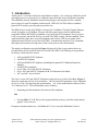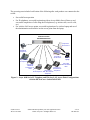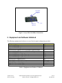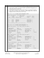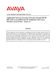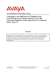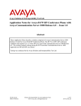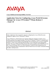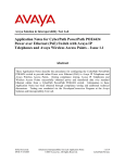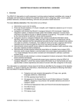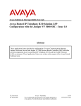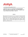
1
Avaya Solution & Interoperability Test Lab
Connecting Avaya 4600 Series IP Telephones and Avaya
Wireless LAN Access Points with the HP ProCurve Switch
2626-PWR (Inline Power Ethernet Switch) - Issue 1.0
Abstract
These Application Notes describe how to connect and configure Avaya 4600 Series IP
Telephones and Avaya wireless LAN access points with the HP ProCurve Switch 2626-PWR
(Inline Power Ethernet Switch). The various Avaya powering arrangements and the
administration commands for displaying and controlling the powering status of the switch
ports are described.
SZ; Reviewed:
WCH 3/18/2004
Solution & Interoperability Test Lab Application Notes
©2004 Avaya Inc. All Rights Reserved.
1 of 10
HP-PoE.doc
1. Introduction
“Inline power” is a feature offered on some Ethernet switches. It is a means by which the switch
can supply power to a network device within the same cable that carries the Ethernet signaling.
This simplifies network installation and powering design, removing the need for a separate
power supply for each IP telephone in the network. IEEE 802.3af-2003 defines a standard
protocol to be used by powering and powered devices.
The HP ProCurve Switch 2626-PWR is a 26-port (24 10/100Base-TX and 2 Gigabit) Ethernet
switch. It supplies its 10/100Base-TX ports with 406 watts of power for PoE applications
compatible with the IEEE 802.3af standard. Avaya 4600 Series IP telephones, Avaya wireless
LAN access points, and the HP ProCurve Switch 2626-PWR comply with this standard. These
Application Notes show how Avaya IP telephones and wireless LAN access points can be
connected to the HP ProCurve Switch 2626-PWR. Command line interface (CLI) commands
that display and control powering status of the switch ports are also demonstrated.
The sample configuration provided in Figure 1 depicts all of the Avaya products that were
provided inline power by the HP ProCurve Switch 2626-PWR. The following Avaya products
are directly connected to the switch:
•
•
•
•
•
•
•
4602 and 4602SW IP Telephones
4610SW IP Telephone
4620 and 4620SW IP Telephones (including the optional EU24 Button Expansion
Module)
4630SW IP Screenphone
Gen-2 4606, 4612, and 4624 IP Telephones
Gen-1 4612 and 4624 IP Telephones with 30A Ethernet Switch Base
AP 3 and AP 5 Access Points
The Gen-1 Avaya 4612 and 4624 IP Telephones require the Avaya 30A Switch Base. Figure 2
shows the connections for the 30A switch base. The 4612 and 4624 telephones can be identified
as Gen-1 or Gen-2 by inspecting the model number. “1A” in the model number indicates Gen-1;
“2A” indicates Gen-2. The model number can be found by:
•
Inspecting the label attached to the bottom of the telephone.
OR
•
Pressing Mute, V, I, E, W, # on the keypad and then pressing * until the model number
appears. Press # to exit.
Examples of model numbers are “4612D01A-003” (Gen-1) and 4612D02A-003 (Gen-2).
SZ; Reviewed:
WCH 3/18/2004
Solution & Interoperability Test Lab Application Notes
©2004 Avaya Inc. All Rights Reserved.
2 of 10
HP-PoE.doc
The powering tests included verification of the following after each product was connected to the
switch:
•
•
•
Successful boot operation
For IP telephones, successful registration with an Avaya Media Server/Gateway and
successful completion of calls using the IP telephones (e.g. initiate calls, receive calls,
etc.)
For wireless LAN access points, successful registration of a wireless laptop and use of
the administration web interface on the access point from the laptop.
HP ProCurve Switch
26262626-PWR (POE Switch)
Avaya AP 5
Access Point
Avaya 4602,
4602SW IP
Telephones
Avaya AP 3
Access Point
Avaya 4610SW
IP Telephone
Wireless
Laptop
Avaya 30A
Avaya 4620,
Ethernet Switch
4620SW IP
Base
Telephones with
Avaya Gen-1
EU24
4612 & 4624 IP
Avaya 4630SW
Avaya Gen-2
Telephones
IP Screenphone 4606, 4612, 4624 IP
Telephones
Figure 1: Avaya 4600 Series IP Telephone and Wireless LAN Access Point Configurations
with the HP ProCurve Switch 2626-PWR
SZ; Reviewed:
WCH 3/18/2004
Solution & Interoperability Test Lab Application Notes
©2004 Avaya Inc. All Rights Reserved.
3 of 10
HP-PoE.doc
To line jack of
4612/4624 IP
Telephone
To PC
To Ethernet
switch port
Figure 2: Avaya 30A Switch Base Connections
2. Equipment and Software Validated
The following equipment and software were used for the sample configuration provided:
Equipment
Avaya 4602 IP Telephone
Avaya 4602SW IP Telephone
Avaya 4610SW IP Telephone
Avaya 4620 IP Telephone with EU24 Button Expansion Module
Avaya 4620SW IP Telephone with EU24 Button Expansion Module
Avaya 4630SW IP Screenphone
Avaya 4606 IP Telephone (Gen-2)
Avaya 4612 IP Telephone (Gen-1, Gen-2)
Avaya 4624 IP Telephone (Gen-1)
Avaya 4624 IP Telephone (Gen-2)
Avaya AP 3 Access Point (Version 2)
Avaya AP 5 Access Point
Avaya 30A Ethernet Switch Base
HP ProCurve Switch 2626-PWR
Software
1.7
1.7
2.0
1.7
2.0
1.8
1.73
1.73
1.73
1.8
2.1.2(412)
2.1.1(375)
H.07.41
Table 1: Equipment and Software Validated
SZ; Reviewed:
WCH 3/18/2004
Solution & Interoperability Test Lab Application Notes
©2004 Avaya Inc. All Rights Reserved.
4 of 10
HP-PoE.doc
3. HP ProCurve Switch Inline Power Commands
This section describes the commands that can be issued to monitor and control inline power
status of the switch ports. Note that, by default, inline power for all ports is enabled. The
commands are listed below, with a brief description by default of their application. Examples of
their use can be found in Section 4.
The CLI commands applicable to inline powering of ports are:
• interface <port-list> power can be used on a port or ports to enable inline powering. The
powered device (PD) will receive power automatically when it is plugged into the switch
port and presents the “maintain power signature.” Note: the key word port-list can be
either an individual port or a range of ports.
• interface <port-list> power [critical | high | low] assigns the port/ports with different
priority levels on power supply.
a. Critical: The switch supplies active PoE support at this level before PDs
connected to High or Low priority ports.
b. High: The switch supplies active PoE support at this level before PDs connected
to Low-priority ports.
c. Low (the default): The switch supplies active PoE support at this level only if
there is power available after supplying active PoE support to ports at the higher
priority levels.
•
•
•
•
no interface <port-list> power removes power from and disables automatic powering of
the connected device. Note that disabling a port that has inline power activated only
disables its network connection, not the inline power.
power threshold <1-99> sets the power consumption percentage at which a trap should
be sent. The range is 1-99 and the default setting is 80.
Show power-management brief shows summary of power status for all ports with
information on power enable status, power priority, detection status and power class.
show power-management <port-list> displays the powering status of the ports defined
by the key word port-list. In addition to the information provided by the command show
power-management brief, the actual power consumed by each telephone and the power
priority are displayed as well. Table 2 shows the required power allocations defined by
IEEE 802.3af-2003, based on the class.
Class
0
1
2
3
Usage
Power
Default
optional
optional
optional
(Watts)
15.4
4
7
15.4
Table 2: IEEE 802.3af Power Classes
SZ; Reviewed:
WCH 3/18/2004
Solution & Interoperability Test Lab Application Notes
©2004 Avaya Inc. All Rights Reserved.
5 of 10
HP-PoE.doc
4. Configure Inline Power Ports
The following CLI session demonstrates configuration and status of inline power ports for use
with Avaya IP telephones and wireless APs.
Steps
1.
•
Description
Attach a serial cable to the console of the HP ProCurve Switch 2626-PWR and log
in. A user name and password are not required to log in unless the user name and
password are pre-set.
HP ProCurve 2626-PWR>enable
HP ProCurve 2626-PWR#
2.
•
•
Enter configuration mode
Enable inline power on all ports
HP
HP
HP
HP
ProCurve
ProCurve
ProCurve
ProCurve
•
For example, to set inline power priority to critical for ports 1-3, use the following
command.
2626-PWR#config t
2626-PWR(config)#interface 1-24 power
2626-PWR(config)#exit
2626-PWR(config)#
HP ProCurve 2626-PWR(config)#interface 1-3 power critical
HP ProCurve 2626-PWR(config)#exit
•
For example, to disable inline power for ports 10-15, use the following command.
HP ProCurve 2626-PWR(config)#no interface 10-15 power
HP ProCurve 2626-PWR(config)#exit
After the execution of the above commands, ports 4-9 and 16-24 are still inline power
enabled with low priority status as defined by the first command interface 1-24 power.
Since the inline power commands can be applied to an individual port or a range of ports,
users have the flexibility to assign switch ports with different power status according to
their needs.
SZ; Reviewed:
WCH 3/18/2004
Solution & Interoperability Test Lab Application Notes
©2004 Avaya Inc. All Rights Reserved.
6 of 10
HP-PoE.doc
Steps
3.
•
Description
Connect several Avaya IP Telephones as shown in Figure 1 to Ethernet ports on the
switch. In this example, Avaya 4620, 4610SW, and 4602SW IP telephones were
connected to ports 1-3 respectively.
Verify that the telephones are powered and booting by inspecting their displays.
Check inline power status of the switch ports. In the example below, all three IP
telephones were in the idle state (no active calls).
•
•
HP ProCurve 2626-PWR#show power-management brief
Status and Counters - Port
| Power
Port | Enable Priority
----- + ------- -------1
2
3
4
|
|
|
|
Yes
Yes
Yes
Yes
Power Status
Configured
Detection
Power
Type
Status
Class
---------------- ----------- ------
Critical
Critical
Critical
Low
Delivering
Delivering
Delivering
Searching
3
2
1
0
----- + ------- -------- ---------------- ----------- -----HP ProCurve 2626-PWR#show power-management 1-3
Status and Counters - Port Power Status for port 1
Power Enable
Priority
Detection Status
Over Current Cnt
Power Denied Cnt
Voltage
Power
:
:
:
:
:
:
:
Yes
Critical
Delivering
0
0
500 dV
7000 mW
Status and Counters
Power Enable
Priority
Detection Status
Over Current Cnt
Power Denied Cnt
Voltage
Power
:
:
:
:
:
:
:
Port Power Status for port 2
Yes
Critical
Configured Type
Delivering
Power Class
0
MPS Absent Cnt
0
Short Cnt
500 dV
Current
3350 mW
Configured Type
Power Class
MPS Absent Cnt
Short Cnt
Current
:
:
:
:
:
3
1
0
140 mA
:
:
:
:
:
2
1
0
67 mA
:
:
:
:
:
1
0
0
64 mA
Status and Counters - Port Power Status for port 3
Power Enable
Priority
Detection Status
Over Current Cnt
Power Denied Cnt
Voltage
Power
SZ; Reviewed:
WCH 3/18/2004
:
:
:
:
:
:
:
Yes
Critical
Delivering
0
0
500 dV
3200 mW
Configured Type
Power Class
MPS Absent Cnt
Short Cnt
Current
Solution & Interoperability Test Lab Application Notes
©2004 Avaya Inc. All Rights Reserved.
7 of 10
HP-PoE.doc
5. Verification Steps
The following steps can be used to verify proper connection, configuration, and powering of
Avaya IP telephones.
1.
•
Disable inline power to port 1 and verify that the telephone loses power
HP ProCurve 2626-PWR(config)#no interface 1 power
HP ProCurve 2626-PWR# show power-management brief
Status and Counters - Port Power Status
| Power
Configured
Detection
Power
Port | Enable Priority Type
Status
Class
----- + ------- -------- ---------------- ----------- -----1
| No
Critical
Disabled
0
2
| Yes
Critical
Delivering
2
3
| Yes
Critical
Delivering
1
4
| Yes
Low
Searching
0
----- + ------- -------- ---------------- ----------- ------
Note that the Power Enable column is set to No, and the Detection Status column indicates that
inline powering is disabled for port 1.
2.
Enable inline power for port 1 and verify that the telephone receives power.
HP ProCurve 2626-PWR(config)#interface 1 power
HP ProCurve 2626-PWR(config)#exit
HP ProCurve 2626-PW#show power-management 1
Status and Counters - Port Power Status for port 1
Power Enable
Priority
Detection Status
Over Current Cnt
Power Denied Cnt
Voltage
Power
SZ; Reviewed:
WCH 3/18/2004
:
:
:
:
:
:
:
Yes
Low
Delivering
0
0
500 dV
7000 mW
Configured Type
Power Class
MPS Absent Cnt
Short Cnt
Current
Solution & Interoperability Test Lab Application Notes
©2004 Avaya Inc. All Rights Reserved.
:
:
:
:
:
3
1
0
140 mA
8 of 10
HP-PoE.doc
6. Conclusion
The following Avaya IP telephone and wireless LAN access point products were tested with the
HP ProCurve Switch 2626-PWR, and were successfully powered:
•
IP telephones:
• 4602 and 4602SW
• 4610SW
• 4620 and 4620SW, including EU24 Button Expansion Module
• 4630SW
• Gen-1 4612 and 4624 with 30A switch base
• Gen-2 4606, 4612, and 4624
•
Wireless LAN access points
• AP 3
• AP 5
SZ; Reviewed:
WCH 3/18/2004
Solution & Interoperability Test Lab Application Notes
©2004 Avaya Inc. All Rights Reserved.
9 of 10
HP-PoE.doc
©2004 Avaya Inc. All Rights Reserved.
Avaya and the Avaya Logo are trademarks of Avaya Inc. All trademarks identified by ® and ™
are registered trademarks or trademarks, respectively, of Avaya Inc. All other trademarks are the
property of their respective owners. The information provided in these Application Notes is
subject to change without notice. The configurations, technical data, and recommendations
provided in these Application Notes are believed to be accurate and dependable, but are
presented without express or implied warranty. Users are responsible for their application of any
products specified in these Application Notes.
Please e-mail any questions or comments pertaining to these Application Notes along with the
full title name and filename, located in the lower right corner, directly to the Avaya Solution &
Interoperability Test Lab at [email protected]
SZ; Reviewed:
WCH 3/18/2004
Solution & Interoperability Test Lab Application Notes
©2004 Avaya Inc. All Rights Reserved.
10 of 10
HP-PoE.doc