1
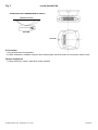
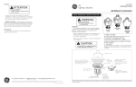
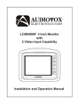
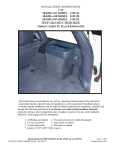
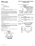
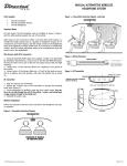
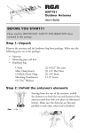
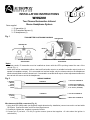
INSTALLATION INSTRUCTIONS
WHS200
Two Channel Automotive Infrared
Stereo Headphone System
Parts supplied
1. IR transmitter (1)
2. IR Transmitter harness (1)
3. IR headphones (2)
Fig. 1
TRANSMITTER POSITIONING DIAGRAM
TRANSMITTER
TRANSMITTER
REAR
FRONT
POSITION IN MIDDLE OF
SEATING AREA
POSITION JUST ABOVE THIGH AREA OF SECOND PASSENGER
ROW SEATING
Notes:
• For best results, IR transmitter must be installed as shown with the LED’s pointing toward the rear of the
vehicle (Fig. 1)
• Audio input can be connected to either a low-level fixed audio output or a variable level audio output (such as a
speaker or headphone output). If it is connected to a low-level output, only the volume control on the headphones
needs to be adjusted to control volume level. If connected to a variable level output, volume adjustment needs to be
done at both the source and at the headphones.
Fig. 2
1. GROUND
2. WHITE
3. RED
4. BLACK
5. RED
1. GROUND
2. WHITE
3. RED
WIRING DIAGRAM
CHANNEL A
1. LEFT RCA CHANNEL IN
2. RIGHT RCA CHANNEL IN
3. DC 12V GND – (NEGATIVE)
4. DC 12V IN + (POSITIVE)
CHANNEL B
1. LEFT RCA CHANNEL IN
2. RIGHT RCA CHANNEL IN
Wire harness with RCA connectors (Fig. 2).
1. Using dual RCA (M/M) cable (not supplied, length determined by installation) connect one end to red and white
RCA jacks. Connect the other end to low level signal source.
2. Connect pin 4 (black wire, negative) to ground of vehicle.
3. Connect pin 5 (red wire, +12 volt) to ignition source (source that supplies +12 volts when the ignition is
switched on).
IN-CAR TRANSMITTER
Fig. 3
ALWAYS FACE LEDs TOWARDS REAR OF VEHICLE
CEILING OF THE CAR
SIDE VIEW
TOP VIEW
IR Transmitter
1. Plug wire harness into transmitter.
2. Fasten transmitter to headliner using two short screws (make sure that screws do not puncture metal of roof).
Wireless headphones
1. Follow directions in owner’s manual for proper operation.
© 2000 Audiovox Corp., Hauppauge, N.Y. 11799
128-5831A