1
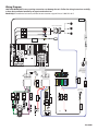
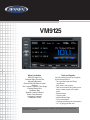
VM9125
What’s in the Box
VM9125 Head Unit
Left and Right Double DIN
Mounting Brackets
Double DIN Half Sleeve Install
Bracket
Two Custom Cosmetic Trim Rings
Parking Brake Wire
Hardware Bag
Speaker Output Harness
Power Input Harness
Accessory Harness
Installation Guide
Tools and Supplies
You will need these tools and supplies
to install your VM9125:
• Torx type, flat-head and Philips
screwdrivers
• Wire cutters and strippers
• Tools to remove existing radio (screw
driver, socket wrench set or other
tools)
• Electrical tape
• Crimping tool
• Volt meter/test light
• Crimp connections
• 18 gauge wire for power connections
• 16 – 18 gauge speaker wire
WARNING! Never install this unit where operation and viewing could interfere with
safe driving conditions.
Optional Equipment
• Rear Camera
Disconnecting the Battery
• T o prevent a short circuit, be sure to turn off the ignition and remove the negative (-) battery cable prior to
installation.
NOTE: If the VM9125 is to be installed in a car equipped with an on-board drive or navigation computer, do not
disconnect the battery cable. If the cable is disconnected, the computer memory may be lost. Under these conditions, use
extra caution during installation to avoid causing a short circuit.
Replacing the Fuse
• When replacing the fuse, use a new 15A replacement fuse. Using a fuse with an improper rating could damage the
unit and cause a fire.
ISO-DIN Installation
This unit is designed to fit into a 2.0 DIN dashboard opening, found in many imported cars. The unit has threaded
holes in the chassis side panels which may be used with the original factory mounting brackets of some Toyota,
Nissan, Mitsubishi, Isuzu, Hyundai and Honda vehicles to mount the radio to the dashboard. Please consult with your
local car stereo specialty shop for assistance on this type of installation.
1. R
emove the existing factory radio from the dashboard or
center console mounting. Save all hardware and brackets
as they will be used to mount the new radio.
2. Remove the factory mounting brackets and hardware from
the existing radio and attach them to the new radio.
CAUTION! Do not exceed M5 X 6MM screw size. Longer screws
may damage components inside the chassis.
3. Place the radio in front of the dashboard opening so the
wiring can be brought through the mounting sleeve. Follow
the wiring diagram carefully and make certain all connections
are secure and insulated with wire nuts or electrical
tape. After completing the wiring connections, plug the
ISO connectors into the mating sockets on the rear of the
chassis. Turn the unit on to confirm operation (vehicle ignition
switch must be “on”). If the unit does not operate,
re-check all wiring until the problem is corrected.
4. Mount the new radio assembly to the dashboard or center
console using the reverse procedure in step 1.
CAUTION! Be careful not to damage the car wiring.
EJE
CT
MU TE
VM91
25
NOTE: It is the end-users responsibility to install and operate this unit in a manner in accordance with local, state and
federal laws. The PARKING BRAKE wire MUST BE CONNECTED as directed in the manual.
CAUTION! Do not block the cooling fan exit. If blocked, the unit may overheat and become damaged.
Installation Using Half-Sleeve
1. Install half-sleeve in the dashboard.
a. Install adapter if necessary (optional).
b. Install half-sleeve into adapter or dashboard (use only
the supplied screws). Do not force the sleeve into the
opening or cause it to bend or bow.
WARNING! Only connect the unit to a 12-volt power
supply with proper grounding.
c. Locate the series of bend-tabs along the top, bottom and
sides of the mounting sleeve. With the sleeve fully inserted
into the dashboard opening, bend as many of the tabs
outward as necessary so that the sleeve is firmly secured
to the dashboard.
2. Use the M5 x 6 screws (provided) to install the mounting
brackets to each side of the radio using the holes indicated
in the diagram. DO NOT USE OTHER SCREWS.
3. Place the radio in front of the dashboard opening so the
wiring can be brought through the mounting sleeve.
4. Complete wiring as illustrated in the wiring diagram. Once
the wiring is complete, reconnect the battery negative
terminal. If there is no ACC available, connect the ACC lead
to the power supply with a switch.
CAUTION! Be careful not to damage the car wiring.
5. After completing the wiring connections, turn the unit on
to confirm operation (ignition switch must be on). If unit does
not operate, recheck all wiring until problem is corrected.
Once proper operation is achieved, turn off the ignition switch
and proceed with final mounting of the chassis.
a. Connect wiring adapter to existing wiring harness.
b. Connect antenna lead.
c.Carefully slide the radio into the half-sleeve, making sure
it is right-side-up. Use the supplied screws to attach the
radio to the half sleeve.
Using the Cosmetic Trim Ring
Step 1-b
Step 1-c
TAB
DASHBOARD
Step 2
Step 5-c
Two cosmetic trim rings are packaged with the head unit for
installation flexibility. This unit will fit into most import dashes
with little or no modification to the dash board/cavity. Some
US domestic vehicle dashes will accept a Double-DIN chassis,
but there is usually a small gap between the radio and dash piece
after installation is complete. In this case, use the appropriate
trim ring to conceal any gaps that may be present.
NOTE: For proper operation of the CD/DVD player, the chassis
must be mounted within 30° of horizontal. Make sure the unit
is mounted within this limitation.
TRIM RING
MOUNTING
SLEEVE
Wiring
Diagram
Wiring
Diagram
CAUTION! IMPORTANT: Incorrect wiring connections can damage the unit. Follow the wiring instructions carefully,
CAUTION!
IMPORTANT:
Incorrect
connectionstechnician.
can damage the unit. Follow the wiring instructions carefully,
or have the
installation
handledwiring
by an experienced
or have
the
installation
handled
by
an
experienced
technician.
Need Help? For technical assistance, call the Jensen customer support line at 1-800-323-4815.
Need Help? For technical assistance, call the Jensen customer support line at 1-800-323-4815.
RADIO ANT
R E AR L
W H IT E
R E AR R
RED
A nte nna J a c k
External Power Amplifier
B LUE
SUB WOOFER
YELLO W
Rear Video
VIDE O O UT
GPS
DVB-T
Antenna
ANT. C O N T
P .C ONT
B L U E /W H IT E
B LUE
GR E E N
Y E LLOW
MUT E
B R O W N (-)
Cell Phone
B LUE
Auto antenna
control (connect
to antenna control
lead and power
supply of antenna
amplifier)
C A ME R A -V ID E O
Y E LLOW
BRAKE
P INK (-)
R E VE R S E
G R E E N /W H I T E ( +)
B LAC K
B AT T
G ND
F I LT E R /F US E
( 20A)
+
IG NIT ION S WIT C H
P UR P LE /B LAC K (-)
P UR P LE (+)
G R E Y (+)
Y E LLOW
RED
AC C
R E AR R
F R O NT R
G R E Y /B LAC K (-)
F R ONT L
WHIT E /B LAC K (-)
WHIT E (+)
G R E E N(+)
G R E E N/B LAC K (-)
R E AR L
Rear View
Video C amer a
-
B AT T E R Y
128-9060