1
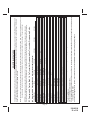
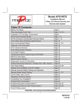
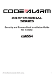
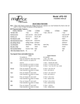
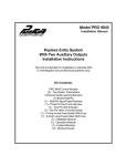
Model PRO9644E
Install Manual
Table Of Contents:
Before You Begin
Wire Harnesses Quick View
Mounting Of The Major Components
6 Pin Power Connector
14 Pin Main Wiring Connector
2 Pin LED / Valet Switch Connectors 4 Pin Shock Sensor Connector
3 Pin Door Lock/Unlock Connector & Wiring
4 Pin Upgrade Telematic Module
Completing The Installation
Dome Delay Learning Proceedure
Adjusting The Shock Sensor
Final Steps Wire Dressing and Operation Explanation
Programming Bank 1 (Transmitters)
Programming Bank 2 (Alarm Features)
Circuit Wiring Layout
Page 2
Page 3
Page 4
Page 5
Page 5 - 8
Page 8
Page 8
Page 8 - 11
Page 12
Page 12
Page 12
Page 12
Page 13
Page 14
Page 14 - 15
Page 16
PATENTED: www.voxxintl.com/company/patents
Page 1
128-9318
1 of 16
Before You Begin
PROFESSIONAL INSTALLATION IS
STRONGLY RECOMMENDED
Roll down window to avoid locking the keys in the vehicle during installation.
Avoid mounting components or routing wires near hot surfaces or near moving
parts like the steering wheel as it may prevent proper operation of the vehicle.
Tape or loom wires under the hood and dash for protection as well appearance.
Use grommets when routing wires through metal surfaces to prevent chafing
and shorting.
Use a Digital Multi Meter for testing and verifying circuits. DO NOT USE A
"TEST LIGHT" OR "COMPUTER SAFE PROBE" as these can set off air
bags or damage sensitive vehicle computers and electronics.
For technical support go to www.avxtech1.com
or call 1 800 225 6074
FCC COMPLIANCE
This device complies with FCC Rules Part 15 and with RSS-210 of Industry Canada.
Operation is subject to the following two conditions:
(1) This device may not cause harmful interference and
(2) This device must accept any interference that may be received, including interference that may cause
undesired operation.
Warning!
Changes or modifications not expressly approved by the party responsible for compliance could void the
user’s authority to operate the equipment.
NOTE: T
he manufacturer is not responsible for any radio or TV interference caused by unauthorized
modifications to this equipment. Such modifications could void the user’s authority to operate the
equipment.
Page 2
128-9318
2 of 16
14 Pin Main Wiring Harness 1 Black/White
2 LT. Green
3 NA
4 Brown
5 DK. Green
6 Purple
7 Orange/White
8 Yellow
9 White/Blue
10 Green/White
11 LT. Blue/Green
12 DK. Blue
13 Green/Black
14 DK. Blue/Black
Part # 1124303
(-) Horn Output
(-) Additional Negative Trigger Input
Empty Cavity
(-) Negative Door Trigger Input
(-) Negative Trigger Input Hood & TNK
(+) Positive Door Trigger Input
(-) Ground Out When Disarmed
Ignition Input (12 VDC On & Start)
(-) Output For Headlight Illumination
(-) Output For Interior Light Illumination
(-) Output Channel 5
(-) Output Channel 3 Trunk
(-) Output Channel 4
(-) Output CH 3 Alternate
6 Pin Power Harness 1
2
3
4
5
6
Red/White
Orange
Black
White/Black
Red
White
Part #1124297
(+) 12VDC Module Power
(-) Starter Inhibit O/P
Chassis Ground
(+) Positive Output For Siren
(+) Parking Relay Power
(+) Parking Relay Output
3 Pin Door Lock Output Harness
1 Red
Part #1122906
Neg. Lock 300mA Max.
Neg. Unlock 300mA Max.
2nd Neg. Unlock 300mA Max.
2 Green
3 Red/Black
Page 3
128-9318
3 of 16
MOUNTING OF THE MAJOR COMPONENTS
Control Module:Part # 1365425
Select a mounting location inside the passenger compartment ( up behind the dash ), and secure using
the two screws or cable ties.
Do Not mount the control module in the engine compartment, as it is not waterproof. You should also
avoid mounting the unit directly onto factory installed electronic components. These components
may cause RF interference, which can result in poor transmitter range or intermittent operation.
Siren: Part # AS9903E
Select a mounting location in the engine compartment that is well protected from access below the vehicle.
Avoid areas near high heat components or moving parts within the engine compartment. To prevent water
retention, the flared end of the siren must be pointed downward when mounted.
Mount the siren to the selected location using the screws and bracket provided.
Hood or Trunk Pin Switch: (Optional) Part #1363699
An optional pin switch should be used for protecting the hood or trunk (or hatchback ) of the vehicle. The
switch must always be mounted to a grounded, metal surface of the vehicle. It is important to select a
location where water cannot flow or collect, and to avoid all drip gutters on hood and trunk fender walls.
Choose locations that are protected by rubber gaskets when the hood or trunk lid is closed. The pin switch
can be mounted using an optional bracket or can be directly mounted by drilling a ¼“ diameter mounting
hole. Keep in mind that when properly mounted, the plunger of the pin switch should depress at least ¼“
when the hood or trunk lid is closed.
Pushbutton LED Combination Switch:
Part # PBLED
Select a mounting location known and accessible to the operator of the vehicle. A dashboard plug or
front dashboard panel is desirable because the pushbutton LED assembly needs the LED to be visible
from the outside of the vehicle. It will be used for valet modes, programming features, programming
transmitters, and for overriding the system when the transmitter is not functioning. Inspect behind the
chosen location to insure that adequate clearance is allowed for the body of the switch, and also that the
drill will not penetrate any existing factory wiring or fluid lines. Drill a 5/16" or 8mm hole in the desired
location and mount the switch by passing the connectors, one at a time, through the panel from the front
side and pressing on the bezel until the switch is fully seated.
Shock Sensor: Part # AS9492a
Select a solid mounting surface for the shock sensor on the firewall inside the passenger compartment,
and mount the sensor using the two screws provided. The shock sensor can also be secured to any fixed
brace behind the dash using tie straps.
Whichever mounting method is selected, make certain that the sensitivity adjustment is accessible for
use later in the installation.
STARTER INHIBIT RELAY:Part # 1363731
Select a mounting location within 12" of the ignition switch's low current start solenoid wire. Secure the relay
to an existing harness in the chosen location using a cable tie around the relay's wiring harness.
Wire the relay as per the diagram found later in this manual.
CAUTION! Do not wire tie the metal bracket to an existing wiring harness as vibration may cause chaffing
and shorting damaging the factory wiring. If an existing harness is not available then secure
the relay's metal mounting tab to an under dash metal brace with a #8 self tapping sheet metal
screw. Wire the relay as per the diagram found later in this manual.
Page 4
128-9318
4 of 16
WIRING THE SYSTEM
6 Pin Power Connector:
P/N 1124297
Red/White (5 Amp) & Red Fused (15 Amp) Wires : +12 VDC Constant Battery Source
This wire supplies power to the alarm's control module as well as the input to the parking light relay.
Connect this input to a constant on +12 Volt supply.
Orange Wire: 300 mA Ground Output When Armed
This wire is provided to control the starter cut relay. Connect the Orange Wire to terminal #86 of the
relay. Connect relay terminal #85 to an ignition wire in the vehicle that is live when the key is in the on
and crank positions and off when the key is in the off position. (This is where the Yellow Wire from the
alarm should be connected).
Cut the low current starter solenoid wire in the vehicle, and connect one side of the cut wire to relay
terminal #87A. Connect the other side of the cut wire to relay terminal #30.
NOTE: T
his is a normally closed starter cut arrangement and when power is removed from the security
system, the starter disable feature will not operate, allowing the vehicle to start. Audiovox does
not recommend using the Orange Wire to interrupt anything but the starting circuit of the vehicle.
Black Wire: Chassis Ground
Connect this wire to a solid, metal part of the vehicle’s chassis. Do not confuse this wire with the thin
black antenna wire that exits the control module independently.
White w/ Black Trace Wire: Positive Output to Siren
Route this wire through a rubber grommet in the firewall, and to the siren location.
Connect the White / Black Wire to the positive wire of the siren. Secure the black ground wire of the siren
to chassis ground.
Red Wire: + 12 Volts Module Supply
See the Red/White Wire above.
White Wire: + 12 VDC Pulsed Parking Light Output (15 Amp Max)
This wire is provided to flash the vehicle’s parking lights. Connect the White Wire to the positive side of
one of the vehicle’s parking lights.
14 Pin Main Wiring Connector
P/N 1124303
1 Black w/ White Trace Wire: 300 mA Horn Output
The Black w/ White Trace Wire is provided to beep the vehicle’s horn. This is a transistorized low current
output, and should only be connected to the low current ground output from the vehicle’s horn switch.
If the vehicle uses a +12 VDC horn switch, then connect the Black w/ White Trace Wire to terminal #86
of the AS 9256 relay ( or an equivalent 30 Amp automotive relay ), and connect relay terminal #85 to
a fused +12 VDC battery source. Connect relay terminal #87 to the vehicle’s horn switch output, and
connect relay terminal #30 to a fused +12 VDC battery source.
Page 5
128-9318
5 of 16
2 Light Green Wire: (-) Instant Trigger Zone 1
This is an instant on ground trigger input intended for the connection of optional triggering devices. The
ground trigger output wire of motion detectors, microwave detectors, or glass break detectors, can be
connected to this Light Green trigger input wire.
3 No Connection, Empty Cavity
4 Brown Wire: - Door Trigger
If the vehicle’s courtesy light switches have a ( - ) ground output when the door is opened (GM and most
Imports), you must connect this wire to the negative output from one of the door switches.
WARNING: Do not use the Brown Wire if the vehicle has +12 Volt output type door switches. (See Purple Wire).
Note for vehicles with interior delay lighting - see programming under the title "Completing
The Installation".
5 Dark Green Wire: ( - ) Instant Trigger Zone
This is an instant on ground trigger wire. It must be connected to the optional previously installed hood
and trunk pin switches when used.
6 Purple Wire: + Door Trigger
If the vehicle’s door courtesy light switches have a +12 Volt output when the door is opened (most Fords
and some Imports), you must connect this wire to the positive output from one of the door switches.
WARNING: D
o not use the Purple Wire if the vehicle has ground output type door switches. (See Brown Wire ).
Note for vehicles with interior delay lighting - see programming under the title "Completing
The Installation".
7 Orange w/ White Trace Wire: 300 mA Ground Output When Disarmed - N. O. Starter Disable
( Optional Relay Required ).
This wire is provided to control the starter cut relay. Connect the orange w/white wire to terminal 86 of
the relay. Connect relay terminal #85 to an ignition wire in the vehicle that is live when the key is in the
on and crank positions, and off when the key is in the off position. (This is where the yellow wire from the
alarm should be connected).
Cut the low current starter solenoid wire in the vehicle, and connect one side of the cut wire to relay
terminal #87. Connect the other side of the cut wire to relay terminal #30.
NOTE: T
his is a normally opened starter cut arrangement, and when power is removed from the security
system, the starter disable feature will remain operational, and the vehicle will not start. Audiovox
does not recommend using the Orange w/ White Trace Wire to interrupt anything but the starting
circuit of the vehicle.
8 Yellow Wire: + 12 VDC Ignition Source
Connect this wire to a source that is live when the key is in the on and crank positions. Be sure that this
source is off when the key is in the off position.
Page 6
128-9318
6 of 16
9 White w/ Blue Trace Wire: Low Current (-) Ground Headlight Output
The White w/ Blue Trace Wire is provided to operate the optional headlamp illumination feature of the
system. This is a low current (300mA) output and must be connected to an external relay to control the
high current switching circuit of the vehicle's headlamps. To use this option, Connect the White /w Blue
Trace Wire to terminal #86 of a P&B VF45F11 relay or equivalent. Connect Terminals #85 and #30 to
a fused +12 Volts source with a current capability equal to or in excess of the factory headlamp fuse.
Connect terminal #87 of the relay to the switched +12 Volt wire feeding the vehicle's headlamp circuit.
NOTE: F
or ground switched headlamp circuits, connect the White /w Blue Trace Wire to terminal #86
of a P&B VF45F11 relay or equivalent. Connect Terminal #85 to a fused +12 Volts source.
Connect terminal #30 to a clean chassis ground. Connect terminal #87 to the ground switched
headlamp control wire in the vehicle.
10 Green w/ White Trace Wire: Entry Illumination Ground Output
This wire provides a 30 second ground output (300 mA Max) whenever the remote is used to disarm the
alarm or to unlock the doors and provides a continuous pulsed output whenever the alarm is triggered. This
wire should be connected to an external relay and wired to the vehicle's interior entry lighting whenever
the optional Interior Illumination circuit is desired. See Wiring Diagram for details.
11 Light Blue/Green Wire: Delayed 300 mA Pulsed Output / Channel 5
The Light Blue/Green Wire pulses to ground via an independent RF channel from the keychain transmitter.
This is a transistorized, low current output, and should only be used to drive an external relay coil.
WARNING: C
onnecting the Light Blue/Green Wire to the high current switched output of trunk release
circuits, some remote start trigger inputs, will damage the control module. Connect the
Light Blue/Green Wire to terminal #86 of a 30 A automotive relay, connect terminal #85 to
a +12 Volt source, and wire the remaining relay contacts to perform the selected function
of channel 5.
12 Dark Blue Wire: Delayed 300 mA Pulsed Output / Channel 3
The Dark Blue Wire pulses to ground via an independent RF channel from the keychain transmitter. This
is a transistorized, low current output, and should only be used to drive an external relay coil.
CAUTION: C
onnecting the dark blue wire to the high current switched output of trunk release circuits,
and some remote start trigger inputs, will damage the control module. In these cases, connect
the Dark Blue Wire to terminal 86 of an Automotive 30 AMP relay, terminal #85 to +12 Volts,
and wire the remaining relay contacts to perform the selected function of channel 3.
13 Green w/ Black Trace Wire: Latching Output / Channel 4
The Green w/ Black Trace Wire latches to ground via an independent RF channel from the keychain
transmitter. This is a transistorized, low current ( 300 mA ) output, and should only be used to drive an
external relay coil.
This wire provides an immediate ground signal, and stays at ground for as long as the button(s) on the
keychain transmitter remains pressed.
CAUTION: C
onnecting the Green w/ Black Trace Wire to the high current switched
output of trunk release circuits will damage the control module.
Connect the Green w/ Black Trace Wire to terminal 86 of the AS 9256 relay (or an equivalent
30 Amp automotive relay ), and wire the remaining relay contacts to perform the selected
function of channel 4.
Page 7
128-9318
7 of 16
14 Dark Blue w/Black Trace Wire: Alternate Channel 3 Output (Dbl. Push Required)
This wire is controlled from the transmitter button programmed to the receiver's channel 3. By double
pressing this the transmitter button, this output will become active for 1 second. This is a transistorized,
low current (300 mA) output, designed to provide an output only when the transmitter is intentionally
operated, such as is the case with remote start add on modules. If you require more than 300mA drive
from this output, you must drive an external relay coil, and arrange the relays contacts to preform the
specified function.
NOTE: Pressing the transmitter button, then immediately pressing and holding it will cause this output
to be active as long as the transmitter button is depressed.
2 Pin White Connector: DASH MOUNTED LED.
Route the red and blue wires in the 2 pin white connector from the LED to the control module, and plug
it into the mating white connector on the side of the module.
2 Pin Blue Connector: PUSH BUTTON VALET SWITCH
P/N PBLED
Route the black and gray wires in the two pin blue connector from the push button valet switch to the
control module and plug it into the mating connector on the side of the module.
4 Pin White Connector: SHOCK SENSOR
P/N 1122591
Route the red, black, blue, and green wires in the 4 pin white connector from the shock sensor to the
control module, and plug one end into the shock sensor, and the other end into the mating white connector
on the side of the module.
Red, Green, & Red / Black 3 Pin White Connector: Door Lock Outputs P/N 1122906
The Red and Green & Red/Black Wires provide a pulsed ground output to the factory door lock control
relay. The maximum current draw through these outputs must not exceed 300 mA. The Red w/Black
Trace Wire will provide an output when the unlock button of the transmitter is pressed a second time after
a first unlock command was issued. This is used for second step unlock or all doors unlock in a two step
circuit. In this arrangement, Green is used to control the drivers door unlock relay, and the Red/Black
Wire will be used to control unlock of all other doors.
3 Wire Ground Switched Single Step Door Locks
In this application, the Red Wire provides a ground pulse during arming, or the pulsed ground lock
output. Connect the Red Wire to the wire that provides a low current ground signal from the factory door
lock switch to the factory door unlock control relay.
The Green Wire provides a ground pulse during disarming, or the pulsed ground unlock output. Connect
the Green Wire to the wire that provides a low current ground signal from the factory door unlock switch
to the factory door unlock control relay.
Red/Black Not Used.
Page 8
128-9318
8 of 16
85
Unlock
87a
87
Lock
Factory Lock Relay
30
86
From Fuse Box + 12 Volts
86
87a
87
To Red Lock Wire
Of Control Module
Factory Unlock Relay
To Green Unlock Wire
Of Control Module
85
30
3 Wire Ground Switched 2 Step Door Locks
In this application, the Red Wire provides a ground pulse during arming or locking, connect the red wire
to the wire that provides a low current ground signal from the factory door lock switch to the factory door
lock control relay.
The Green Wire provides the first ground pulse during disarming or unlocking, connect this wire to the
drivers door unlock relay that requires a low current ground signal to unlock only the drivers door.
If the vehicle does not have a separate drivers door relay, one will have to be added. Locate the drivers
door unlock motor wire and cut it at a convenient location to allow wiring of an optional relay.
Connect the door side of the cut wire to terminal #30 of the optional relay added.
Connect the vehicle side of the cut wire to terminal #87a of the optional relay added.
Connect the green wire of the 3 pin harness to terminal #86 of the optional relay added.
Connect terminal #85 of the optional relay added to a fused constant +12 Volt source.
Most vehicles door lock/unlock motor legs rest at ground, and switch +12 Volts to the door lock/unlock
motor legs for operation, if this is the case in the vehicle you are working on, connect the remaining
terminal, #87, to a fused +12 Volt source.
In the rare instance that the vehicle door lock/unlock motor legs rest at +12 Volts and switches ground to
the door lock/unlock motors, connect he remaining terminal, #87, to chassis ground.
The Red/Black Wire provides a pulse ground output when the unlock button of the transmitter is pressed
a second time after disarming.
Connect the Red/Black Wire to the wire that provides a low current ground signal from the factory door
unlock switch to the factory door lock control relay.
Page 9
128-9318
9 of 16
85
Unlock
87a
87
Lock
Factory Lock Relay
Drivers Door Motor
30
86
Passenger Door Motors
From Fuse Box + 12 Volts
86
To Red Lock Wire
Of Control Module
87a
87
Factory Unlock Relay
To Red/Black 2nd
Unlock Wire From
Control Module
X
30
85
Cut Drivers Door
Unlock Motor Wire
Fused + 12 Volt Source
To Green Unlock Wire
Of Control Module
86
87a
85
If Factory Switches + 12 Volts
Connect to Fused + 12 Volt Source.
If Factory switches Ground,
Connect To Ground.
87
30
3 Wire Positive Switched Door Locks:
For three wire positive door lock circuits, you will have to invert the output of the door lock wires, with
relays or with the "DLVI" Door Lock Voltage Inverter. The DLVI converts a negative pulse to a 1A positive
pulse. When using the DLVI, cut the 3 Pin Green & Blue Connector, and splice the Blue from the DLVI
to the Green Door Unlock Wire of the 2 or 3 pin module's door lock harness, and splice the Green of the
DLVI to the Red Door Lock Wire of the 2 or 3 pin module's door lock harness. Connect the Red from the
DLVI to a fused 12 Volt Source. Connect the Blue (+) Unlock control output from the DLVI to the vehicle's
low current (+) Door Unlock Wire. Connect the Green (+) Lock control output fromthe DLVI to the vehicle's
low current (+) Door Lock Wire.
85
Unlock
87a
87
Lock
Factory Lock Relay
30
86
From Vehicle
Chassis Ground
(+)
When Using DLVI
86
To Red Lock Wire
Of Control Module
To Green Unlock Wire
Of Control Module
87a
87
Green
X
Factory Unlock Relay
Blue
85
Cut and Splice
Per the Install
Guide Instruction
30
Factory Lock Relay
85
87a
87
When Using Relays
To Red Lock Wire
Of Control Module
To Green Unlock Wire
Of Control Module
30
86
To Fused + 12 Volts
85
86
87a
87
30
To Fused + 12 Volts
Factory Unlock Relay
Page 10
128-9318
10 of 16
3 Wire Positive Switched 2 Step Door Locks
Connect the DLVI as mentioned above, or use relays to invert the negative output pulse from the 3 pin
connector Red & Red/Black to control the lock & all door unlock functions by properly arranging the relay
contacts to pulse the vehicle's lock wire, and unlock wire respectively.
For the driver priority unlock, if the vehicle does not have a separate drivers door relay, one will have to
be added. Locate the drivers door unlock motor wire and cut it at a convenient location to allow wiring
of an optional relay.
Connect the door side of the cut wire to terminal #30 of the optional relay added.
Connect the vehicle side of the cut wire to terminal #87a of the optional relay added.
Connect the Green wire of the 3 pin harness to terminal #86 of the optional relay added.
Connect terminal #85 of the optional relay added to a fused +12 Volt source.
Most vehicles door lock/unlock motor legs rest at ground, and switch +12 Volts to the door lock/unlock
motor legs for operation, if this is the case in the vehicle you are working on, connect the remaining
terminal, #87, to a fused +12 Volt source.
In the rare instance that the vehicle door lock/unlock motor legs rest at +12 Volts and switches ground to
the door lock/unlock motors, connect he remaining terminal, #87, to chassis ground.
85
Unlock
87a
87
Factory Lock Relay
Lock
30
86
Drivers Door Motor
When Using DLVI
To Red Lock Wire
Of Control Module
To Green Unlock Wire
Of Control Module
Passenger Door Motors
From Vehicle
Chassis Ground
(+)
86
87a
87
Factory Unlock Relay
Green
X
Blue
85
Cut and Splice
Per the Install
Guide Instruction
30
X
Factory Lock Relay
85
87a
Cut Drivers Door
Unlock Motor Wire
87
When Using Relays
To Red Lock Wire
Of Control Module
30
86
To Fused + 12 Volts
To Red/Black 2nd
Unlock Wire Of Control Module
85
87a
87
Fused + 12 Volt Source
86
86
87a
87
30
To Fused + 12 Volts
Factory Unlock Relay
85
If Factory Switches + 12 Volts
Connect to Fused + 12 Volt Source.
If Factory switches Ground,
Connect To Ground.
30
To Green Unlock Wire
Of Control Module
Resistive Circuits, As Well As 4 Wire Polarity Reversal and
5 Wire Alternating 12 Volt Door Lock Control Circuits
These applications require the use of additional components which may include relays, fixed resistors,
a door lock interface, or a data module. You can search the vehicle @ www.avxtech1.com, Flash-It.com
for vehcile specific information, or contact our tech service line or web site for additional information.
Page 11
128-9318
11 of 16
4 Pin Upgrade Telematic Module:
Red = + 5 Volts
Black = Ground
White = Data TX
Yellow = Data RX
Connect the 4 pin harness found in the Telematic one way module kit to the mating port on the telematic
module and the other side to the connector on the alarm or keyless entry module.
NOTE: If using the TWO WAY Telematic module, only Ground, TX, and RX are used on this port, the
+12 Volt supply for the two way module must be sourced separately or the unit will not operate.
COMPLETING THE INSTALLATION
NOTE: T
his unit has the ability to learn the dome light delay time, up to 60 seconds. If the vehicle
has delay interior lights, and you wish to avoid three chirp, defect zone, indication normally
associated with this type of interior light, we suggest you learn the interior light delay.
TO LEARN THE DOME LIGHT ENTRY DELAY START WITH ALL DOORS CLOSED:
1. Use the transmitter to Lock / Unlock / Lock / Unlock / Lock / Unlock / Lock, the system. The LED
turns on solid to confirm the system entered the learn mode.
2. Immediately open and close the door of the vehicle to initiate the dome delay. The unit will monitor
the door trigger input Positive, (Purple), and Negative, (Brown) when active. When the dome light
turns off, the unit will add 2 seconds then exit the learn mode.
3. The LED will begin flashing the Armed indication indicating the unit has exited the learn mode and is
armed.
Antenna Wire:
Be sure to extend the thin black antenna wire to its full length, and cable tie into place where it cannot
be damaged. Avoid wrapping this wire around major, high current wire looms.
Adjusting the Shock Sensor: P/N AS9492A
If used, the sensitivity of the pre - detect circuit is automatically set 30% less sensitive than the full trigger
circuit.
Using a small screwdriver, gently turn the adjustment screw fully counterclockwise. (DO NOT over turn
this screw. Maximum rotation for this adjustment is 270°). Close the hood and trunk lids, and arm the
alarm. Wait 6 seconds for the accessories trigger zone to stabilize, then firmly strike the rear bumper with
the side of a closed fist considering the amount of force required to break a window.
WARNING: N
ever perform this test on the vehicle’s glass, as you may break the window. Turn the
adjustment screw clockwise (increasing sensitivity) about ¼ turn and re-test. Repeat this
procedure until the alarm sounds. Ultimately, one firm strike to the rear bumper will cause
the alarm to emit pre-detect warning tones.
CAUTION: S
etting the sensitivity too high can cause false alarms due to noise vibrations from passing
trucks and heavy equipment. To decrease sensitivity, turn the adjustment screw counter
clockwise.
Page 12
128-9318
12 of 16
Wire Dressing:
Always wrap the alarm wires in convoluted tubing, or with a spiral wrap of electrical tape. Secure these
looms along the routing using cable ties. This will ensure that the alarm wires are not damaged by falling
onto hot or sharp moving surfaces in the vehicle.
Operation:
Take a few moments to check off the appropriate option boxes in the owner’s manual, and to fully
explain the operation of the system to your customer.
Page 13
128-9318
13 of 16
PROGRAMMING BANK 1 (TRANSMITTERS):
1. Turn the ignition key to the on position.
2. Press and release the valet/programming switch 3 times (Siren Chirps).
3. Press the Lock Button of each transmitter you want programmed until you hear a chirp from the horn
or siren.
4. Turn the ignition switch off.
The above action programs the Lock, Unlock, Start/Trunk, and Option 1 buttons of the system. For additional channel programming see transmitter programming guide found within the literature bag packaged
with this kit.
PROGRAMMING BANK 2 (ALARM FEATURES):
You can enter bank 2 from bank 1 by turning the ignition key off then on from step 4 of Bank 1.
(Siren Short then Long Chirp), or You can also go right to bank 2 by:
1. Turn the ignition key to the on position.
2. Press and release the valet/programming switch 3 times (Siren Chirps).
3. Turn the ignition key off then on. (Siren Short Then long Chirp)
4. Press the pushbutton switch once to advance to feature 1, twice to advance to feature 2, etc,,, then
use the lock button of the transmitter to select the feature setting.
Example to set passive arming:
1. Turn the ignition key to the on position.
2. Press and release the valet/programming switch 3 times (Siren Chirps).
3. Turn the ignition key off then on. (Siren Short Then long Chirp)
4. Press the pushbutton switch six times to advance to features 6, Pass/Act Arm, then use the lock button
of the transmitter to select two chirps "Passive Arm".
5. To exit the programming mode, turn the ignition key off. The program mode is automatically exited 6
seconds after the ignition switch transitions off.
The selectable features of this unit can be set manually as explained above, or online by using our web
link. The Accessory VE-PROG kit will include the necessary cables to connect to your computer along
with the web access information and application required to take advantage of this feature.
If Programming via PC while connected to +12 VDC, (Already Installed), you must manually enter the
programming mode as shown below:
1. Turn the ignition on.
2. Press and release valet switch 3 times.
3. Turn ignition off then on, off then on, off then on, off then on to enter web/on-line feature selection
Bank 5. Siren chirps 5 times indicating access to feature program mode.
4. Launch the application on your PC. Connect the module via the USB to DBI harness and follow
program prompts.
New ,The chirp and LED patterns have been changed to make it easier to determine what feature you
are in. As well, the feature bank will not time out until the ignition switch is off for more than 5 seconds.
The change will be noted when you get to feature # 11, the LED pattern will be 1 pause, 1, #12 will be 1
pause, 2, #13 will be 1 pause 3, #18 will be 1 pause 8, etc,,,. This will make it eaised for the technician
to determine what feature they are up to.
Feature Bank Reset: If you wish to reset a feature bank to the default settings,,, from within that bank,
press and hold the pushbutton on the receiver/antenna for 5 seconds or until a chirp / flash is heard from
the system. This action resets the feature bank. The feature banks are reset individually so resetting Bank
2 will not effect bank 3 & visa versa.
Page 14
128-9318
14 of 16
Page 15
128-9318
15 of 16
SELECTABLE FEATURES
If Programming via PC while connected to +12 VDC you must manually enter the programming mode as shown below:
1. Turn the ignition on.
2. Press and release valet switch 3 times.
3. Turn ignition off then on, off then on, off then on, off then on to enter web/on-line feature selection Bank 5. Siren chirps 5 times indicating access
to feature program mode.
4. Launch the aapplication on your PC,,Connect the module via the USB to DBI harness and follow program prompts.
Feature Selection
1 Chirp
2 Chirps
3 Chirps
4 Chirps
5 Chirps
6 Chirps
1st DoorL/UL 500 mS
3.5 Sec.
500mS L, Dbl. U/L Dbl L, 500mS UL Dbl L, Dbl UL
500mS/350mS ul
2nd Accy Lock
Auto Lock On
Auto Lock Off
3rd Accy. UL
Auto UL Dr.
Auto UL All
Auto UL Off
4th HeadlightsOn ArmOn DisarmOn Both
Off
5th Passive Locks
Passive Active 6th Pass/Act Arm Passive Arm
Active Arm
7th Siren/Horn
Siren/Horn
Siren OnlyHorn Only
8th Horn Chirp
10mS
16mS30mS40mS50mS
9th O/R Method
Custom Code
Valet
10th 2 Step U/L
On
Off
11th Chp Del Tx
On Off
12th Trigger Circuits
Not Available
13th L/UL Poll
Not Available
14th Aux Ch 5 Sel
Pulse
Push & Hold
10 Sec
20 Sec
Latch On/Off
Hold 3/S For O/P
15th Aux Ch 6 Sel
Not Available
16th Aux Ch 7 Sel
Not Available
17th Trigger Delay
Not Available
18th Data Port Select
DBI Protocol
ADS Protocol
RF Programmable Features Bank 2 Is Alarm Selectable Features:
RF Programmable Feature Bank 1 Is For Transmitter Programming See Transmitter Programming Guide.
NOTE: Manual programming Keyless Entry Models with no horn output will Flash the Parking Lights instead of chirp where chirp is indicated.
Also, No data will be indicated if a feature is not available for a particular model. The unit will enter the feature but no selection will be available.
Note: The method of manual override can either be selected to operate from the valet switch or operate by custom code. Custom Code programming is found in
the owners guide. Be certain to place a check mark indicating the method used in the box located on the last page of the owner's manual.
The selectable features of this unit can be set manually as explained on the previous page, or online by using our web link. The Accessory VE-PROG kit will
include the necessary cables to connect to your computer along with the web access information and application required to take advantage of this feature.
Factory default settings are indicated by BOLD text below.
Connector For Telematic
Unit When Used
Red = (-) Lock
Green = (-) Unlock
Red/Black = (-) 2nd Unlock
Pushbutton
LED Assembly
PRO9644E
Antenna Wire, Route As High
As Possible And Away From
Other Electronic Modules For Best Range
Red (+)
Black ( Ground)
Green ( Full Trigger)
Blue (Pre Detect)
To Shock Sensor
Red/White (+) 12 VDC
15A
To FlashLogic
Module When Used
5A
White Parking Light Output (+)
Black (Chassis Ground)
Red (+) Parking Light Input
Orange (-) Output To Starter Inhibit Relay
White/Black (+) Siren Output
DK. Blue/Black (-) Alternate Channel 3 Output
Orange/White (-) Ground When Disarmed N.O. Starter Inhibit
Green/Black (-) Channel 4 Output
Purple (+) Positive Door Trigger Input
DK. Blue (-) Channel 3 Output Trunk Release
DK. Green (-) Instant Hood & Trunk Trigger Input
LT. Blue/Green (-) Channel 5 Output
Brown (-) Negative Door Trigger Input
Green/White (-) Dome Light Control Output
Empty Cavity No Connection
White/Blue (-) Headlight Control Output
LT. Green (-) Sensor Trigger Input
Yellow (+) Ignition Input 12 VDC On & Start
Black/White (-) Horn Output
2014 Voxx Electronics Corporation 150 Marcus Blvd. Hauppauge N.Y. 11788
128-9318
Page 16
128-9318
16 of 16