1
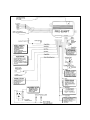
Model PRO 9246FT
Installation Manual
PRE-INSTALLATION NOTES:
PASSIVE / ACTIVE DOOR LOCK SELECTION: DIP SWITCH #1
This feature will only affect the operation of the system if the passive arming feature is selected.
When active door lock is selected, the doors will only lock when the transmitter button is pressed. When the alarm is
allowed to arm passively, at the end of the 30 second arming cycle, the doors will not automatically lock. The system
is shipped in the active door lock mode, therefore, no modifications are required for this feature.
When passive door lock is selected, when the system is allowed to arm passively, at the end of the 30 second arming
cycle, the doors will automatically lock. To program this feature, move dip switch number 1 to the on position.
AUTO LOCK / UNLOCK: DIP SWITCH #2
The system is shipped with this feature activated.
Any time the ignition key is turned to the off position, the doors will automatically unlock. Any time the ignition key is turned
to the on position, the doors will automatically lock when doors are closed.
To disable the auto lock / unlock feature, move dip switch number 2 to the “off” position.
PASSIVE / ACTIVE ARMING SELECTION: DIP SWITCH #3
This alarm can be programmed to operate as either a “PASSIVE” or “ACTIVE” arming security system.
As a “Passive” alarm, the system will automatically arm itself approximately 30 seconds after the ignition key is turned
off, one door is opened, then all vehicle doors are closed, (arming is suspended until the last door is closed). This feature
protects the vehicle in the event you forget to arm the system using the keychain transmitter. The doors will operate
according to the position of dip switch number 1.
This system is shipped in the passive mode, therefore no modifications are required to make the system operate as
a “Passive” alarm.
As an “Active” alarm, the system can only be armed using the keychain transmitter. There will be no backup automatic
arming.
To make the system operate as an “Active” alarm, move dip switch number 3 to the off position.
INOPERATIVE: DIP SWITCH #4
CHANNEL 2 OUTPUT:
This system provides an on board 10 A relay to activate the factory installed trunk release solenoid.
CHANNEL 3 OUTPUT:
This system provides an additional hardwire remote output to control an assortment of optional upgrades.
This output is an independent channel from the transmitter, and is controlled by pressing both buttons on the transmitter
simultaneously. It is a low current ground pulse (300 mA maximum), and the duration or length of the pulse varies (this
output will provide a ground signal for as long as both buttons are held), making it a versatile feature. This output can
be used to control;
* Optional Remote Starter AS 9075
* Optional Window Roll Up AS 9153
REMOTE ENTRY ILLUMINATION:
This system provides an on board relay that will illuminate the dome light for 30 seconds whenever the system is
disarmed.
This circuit will also flash the interior dome light when the alarm is triggered.
Since both the NO and COMMON relay contacts are wired through the harness, this feature can be used with both
positive and negative switched dome light circuits.
DARK GREEN w/ WHITE TRACE WIRE: ENTRY ILLUMINATION
The dark green w/ white trace wire provides the entry lighting, and flashes the vehicles dome light when the alarm
is activated.
This is the COMMON contact of an on board, 10 A maximum, relay.
Connect the dark green w/ white trace wire to the switched output of one of the door pin switches.
NOTE: When wiring this feature in vehicles with factory equipped delay lighting circuits, it is best to connect to the
output of the timer which feeds the dome light, rather than at the door switch. This will ensure that the dome light
pulses when the alarm is triggered.
DARK BLUE w/ WHITE TRACER WIRE: DOME LIGHT RELAY SOURCE
This wire is the source for the on board entry illumination feature. This wire also activates the passive arming feature,
therefore, it is important to use this connection as source for entry illumination, and the Dark Green w/ White tracer wire
for the output to the dome light circuit.
Connect the Dark Blue w/ White tracer wire to chassis ground if the vehicle’s dome light circuit is ground switched, or
to a + 12 VDC constant battery source if the vehicle’s dome light circuit is positive switched.
NOTE: Be sure to set the jumper location on the control module to either positive or negative dome light switching.
YELLOW w/ RED TRACER: + 12 VOLT OUTPUT WHEN DISARMED
This wire provides a + 12 volt output whenever the system is disarmed or the ignition key is on. This output can be used
to control the arm / disarm functions of a passive security system.
Connect the Yellow / Red wire to the 12 volt control wire of the passive security system.
If there is no security system in the vehicle, securely tape the end of this wire.
GREY & BLACK 2 PIN (blue) CONNECTOR: VALET SWITCH
Route the two conductor, blue connector from the valet switch to the alarm control module, and plug it into the mating
blue connector on the end of the module.
6 PIN DOOR LOCK OUTPUT CONNECTOR: NORMAL OPERATION
The orange, blue w/white tracer, yellow, white, green, and blue wires in the 6 conductor connector are the contacts of
the on- board door lock relays. The function of each of these wires is listed below;
2-STEP UNLOCK:
This system uses on board door lock relays, and will allow for the 2-step unlock feature.
The 2-step unlock feature will work with most fully electronic door lock circuits. The vehicle must have an electronic
door lock switch (not the lock knob or key switch), which locks and unlocks all of the vehicle's doors.
When wired for this feature, pressing the disarm button on the transmitter one time will disarm the alarm and unlock
only the driver's door.
If, as you approach the vehicle; the transmitter button is pressed two times within 3 seconds, the alarm will disarm
and all doors will unlock.
POSITIVE / NEGATIVE TRIGGER JUMPER: ON BOARD JUMPER
This control module has an on board, hard wire jumper located beside the dip switches, that must be set prior to
installing the system. This jumper is used to determine the polarity of the door trigger circuit.
If the vehicle has a ground switched dome light circuit, be sure this jumper is connected to the negative terminal on
the circuit board.
If the vehicle has a positive switched dome light circuit, be sure this jumper is connected to the positive terminal on
the circuit board.
-2-
PARKING LIGHT FLASHER:
This system provides an output to control an optional parking light flasher relay (not included).
When this option is installed, the vehicles parking lamps will flash during arm, disarm, intrusion, and emergency panic.
This is a ground (300 mA maximum) output, therefore, a relay must be used to take advantage of this feature.
STARTER DISABLE:
This system provides an output to control an optional starter cut relay (not included).
When this option is installed, any time the system is armed, the vehicles starting circuit is inoperable.
TRANSMITTER PROGRAMMING:
The transmitters included in this kit have been programed at the factory for the Channel 1 (Lock /Arm, Unlock/Disarm,
and panic function) only.
Any additional functions of the system (receiver Channels 2 and 3) must be programed at the time of installation. These
functions can be assigned to the Option transmitter button, or a simultaneous press of the Lock/Unlock/ and Option
buttons.
Refer to the transmitter programming guide, included in this package, for more details regarding transmitter button
assignments and system functions.
INSTALLATION HOT LINE:
If at any time during the installation you require technical assistance, call toll free 1-800-225-6074 for the Audiovox
Installation Hot Line.
MOUNTING THE COMPONENTS:
CONTROL MODULE:
Select a mounting location inside the passenger compartment ( up behind the dash ), and secure using two screws
provided.
The control module can also be secured in place using cable ties.
Do not mount the control module in the engine compartment, as it is not waterproof. You should also avoid mounting
the unit directly onto factory installed electronic components. These components may cause RF interference, which
can result in poor transmitter range or intermittent operation.
VALET SWITCH:
Select a desired mounting location for the switch, that is easily accessible to the driver of the vehicle.
The switch does not have to be concealed, however, concealing the switch is always recommended, as this provides
an even higher level of security to the vehicle. The switch may be mounted in the dash by drilling a 1/4" diameter hole
in the location. Be sure to check behind the dash for adequate clearance for the body of the switch, and to confirm that
the drill will not damage any existing components as it passes through the dash.
Make certain the back of the switch is accessible for wiring later in the installation.
WIRING THE SYSTEM:
RED w/ WHITE FUSED WIRE : + 12 VOLTS CONSTANT BATTERY SOURCE
Connect the Red w/ White tracer wire to a + 12 VDC constant battery source.
BLACK WIRE: CHASSIS GROUND
Connect this wire to a solid, metal part of the vehicle’s chassis.
Do not confuse this wire with the thin black antenna wire that exits the control module independently.
YELLOW WIRE: + 12 VDC IGNITION SOURCE
Connect this wire to a source that is hot when the key is in the on and start positions, and off when the key is in the off
position.
-3-
ORANGE WIRE: 300 mA GROUND OUTPUT WHEN ARMED
This wire is provided to control the optional (not included) starter cut relay. Connect the orange wire to terminal 86 of
the AS 9256 relay (or an equivalent 30 A automotive relay), and wire the remaining relay contacts as shown in the wiring
diagram.
IMPORTANT: Audiovox does not recommend using this relay to interrupt the ignition wire. Only
connect this relay to the low current starter solenoid feed wire, as indicated on the wiring diagram.
WHITE WIRE: 300 mA PULSED GROUND PARKING LIGHT OUTPUT
This wire is provided to control an optional ( not included ) parking lamp flasher relay. Connect the white wire to terminal
86 of the AS 9256 relay ( or an equivalent 30 A automotive relay ), and wire the remaining relay contacts as shown in
the wiring diagram.
DARK GREEN w/ BLACK TRACE WIRE: LATCHING OUTPUT / CHANNEL 3
The green w/ black tracer wire latches to ground via an independent RF channel from the keychain transmitter. This
is a transistorized, low current (300 mA.) output, and should only be used to drive an external relay coil.
This wire provides an immediate ground signal, and stays at ground for as long as the buttons on the keychain transmitter
remain pressed.
WARNING! Connecting the dark green w/ black tracer wire to the high current switched output of trunk release
circuits, some remote starter trigger inputs, and some window roll up trigger inputs, will damage the control module.
Connect the dark green w/ black tracer wire to terminal 86 of the AS 9256 relay (or an equivalent 30 A automotive relay),
and wire the remaining relay contacts to perform the selected function of channel 3.
2 DARK BLUE WIRES: PULSED OUTPUT / CHANNEL 2 (TRUNK RELEASE)
The dark blue wires are controlled via an independent RF channel from the keychain transmitter. These are the NO and
COMMON contacts of an on board, 10 A relay, so they can be connected to positive or negative switched circuits.
Connect one of the dark blue wires to the output of the trunk release push-button switch, and the other dark blue wire
to either chassis ground, or + 12 VDC battery, depending on the polarity of the trunk release circuit in the vehicle.
When using this channel for an accessory other than trunk release, connect one dark blue wire to the accessory, and
the other dark blue wire to either chassis ground, or, to a fused + 12 volt battery source, depending upon the requirements
of the accessory.
WARNING: Never attempt to pull more than 10 Amperes of current through this relay. The circuit will be damaged.
Always check the requirements of accessories prior to connecting them to the circuit.
LOCK RELAY
UNLOCK RELAY
BLUE/WHITE
=
N.O. CONTACT
ORANGE
=
N.O. CONTACT
GREEN
=
N.C. CONTACT
BLUE
=
N.C. CONTACT
YELLOW
=
COMMON CONTACT
WHITE
=
COMMON CONTACT
3 WIRE GROUND SWITCHED DOOR LOCK CIRCUITS:
In these vehicles, the dark green and dark blue door lock wires are not used.
The orange and blue w/white stripe wires must be connected to a chassis ground source.
The yellow wire is the ground pulse "lock" output, and should be connected to the negative lock wire in the vehicle.
The white wire is the ground pulse "unlock" output, and should be connected to the negative unlock wire in the vehicle.
3 WIRE POSITIVE SWITCHED DOOR LOCK CIRCUITS:
In these vehicles, the dark green and dark blue door lock wires are not used.
The orange and blue w/white stripe wires must be connected to a +12 volt battery source.
The yellow wire is the positive pulse "lock" output, and should be connected to the positive lock wire in the vehicle. The
white wire is the positive pulse "unlock" output, and should be connected to the positive unlock wire in the vehicle.
-4-
5 WIRE ALTERNATING DOOR LOCK CIRCUITS:
In this application, it is necessary to cut the existing door lock by-pass wires. These wires run from the master door
lock switch to the slave door lock switch, and then on to the door lock motors.
Cut the existing lock wire, and connect the yellow wire to the slave switch or motor side of the cut wire. Connect the green
wire to the master switch side of the cut wire.
Cut the existing unlock wire, and connect the white wire to the slave switch or motor side of the cut wire. Connect the
blue wire to the master switch side of the cut wire.
The orange and blue w/white stripe wires must be connected to a fused +12 VDC battery source.
Refer to the AUDIOVOX Door Lock Wiring Supplement for proper connection of these wires into the various locking
circuits available in current vehicles.
6 PIN DOOR LOCK OUTPUT CONNECTOR: 2-STEP OPERATION
When wiring for 2-step unlock operation, you must connect the outputs of the on-board unlock relay to the driver's side
door lock motor. Wire these outputs as follows;
Orange = N.O. Relay Contact to +12 VDC Battery
Dark Blue = N.C. Relay Contact to Motor leg switch side
White = Common Relay Contact to Motor leg motor side
Wire the transistorized negative "all doors unlock" output directly to the negative unlock wire from the door lock switch
in vehicles with 3 wire ground switched circuits.
In vehicles with 3 wire positive or 5 wire alternating switched circuits, you must add a 30 Amp automotive relay to provide
the "all doors unlock" feature.
RED w/BLACK & GREEN w/BLACK 2 PIN RED CONNECTOR: 2-STEP UNLOCK CONNECTOR
The Green w/Black tracer wire provides a 300 mA ground pulse output for the all doors unlock signal, and can be
connected to the negative door unlock wire in 3 wire negative switched vehicles.
The Red w/Black tracer wire provides a +12 VDC source for those applications that require a relay for the all doors unlock
feature.
COMPLETING THE INSTALLATION:
ANTENNA WIRE: Be sure to extend the thin black antenna wire to its full length, and cable tie into place where it cannot
be damaged. Avoid wrapping this wire around major, high current wire looms.
OPERATION: Take a few moments to check off the appropriate option boxes in the owner’s manual, and to fully explain
the operation of the system to your customer.
WIRE DRESSING: Always wrap the alarm wires in convoluted tubing, or with a spiral wrap of electrical tape. Secure these
looms along the routing using cable ties.
This will ensure that the alarm wires are not damaged by falling onto hot or sharp moving surfaces in the vehicle.
© 1999 Audiovox Corp., 150 Marcus Blvd., Hauppauge, N.Y. 11788
-5-
128-5338A
-6-