1
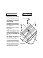
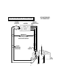
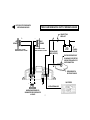
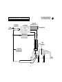
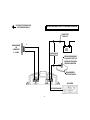
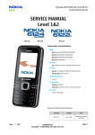
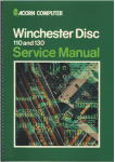
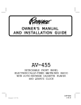
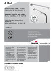
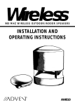
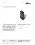
Model PA-S2150
600 Watt Stereo Amplifier
Owner's
Manual
INDEX
Specifications................................................................................1
Precautions ...................................................................................2
Installation Instructions .................................................................3
Wiring Instructions ................................................................4 - 5
Stereo and Mixed-Mono Input Wiring Diagram .............................6
Stereo and Mixed-Mono Output Wiring Diagram .........................7
Mono (Bridged) Input Wiring Diagram ...................................... 8
Mono (Bridged) Output Wiring Diagram ................................... 9
Operation ...........................................................................10 - 11
Warranty ............................................................ Inside Back Cover
HIGH PERFORMANCE STEREO AMPLIFIER
This power amplifier has been designed to provide high quality performance with a
minimum of maintenance. However, it's performance will only be as good as the care
and quality of components with which it is installed. We therefore advise that you
read these instructions very carefully to familiarize yourself with the product and it's
features.
Should you require assistance with the installation or wiring of this unit, please call
our toll-free "HELP" line at 1-800-645-4994 during the days/hours shown.
HELP!
1-800-645-4994
Monday-Friday 8:30am-7:00pmEastern
Saturday
9:00am-5:00pmEastern
SPECIFICATIONS
Maximum Output Power:
Stereo Operation:
Mono Operation:
Output Power @ 0.05% T.H.D.:
Stereo Operation:
Mono Operation:
Output Impedance:
Frequency Response:
Channel Separation:
Signal / Noise Ratio:
Input Impedance:
300 watts x 2
600 watts x 1
Input Sensitivity:
150 watts RMS x 2
400 watts RMS x 1
2 - 8 ohms (stereo)
4 - 8 ohms (mono)
10 - 50,000 Hz. ± 1 dB
50 dB
93 dB (A-Weighted)
Filter Types:
Filter Slope:
Filter Crossover:
Bass Boost:
Supply Voltage:
Fuse Rating:
Dimensions (W x H x D):
* Due to continuing improvement, Audiovox reserves the right to change features and design without notice.
-1-
low-level 10K ohms
high-level 100 ohms
low-level 200 mv. - 4 v.
high-level 2 - 10 v.
low-pass and hi-pass
18 dB/octave
50 - 180 Hz. (selectable)
+8 dB @ 45 Hz.
12 volts, negative ground
30 amps. x 2
10-3/4" x 2-3/8" x 12"
273 mm x 62 mm x 300 mm
PRECAUTIONS
1. Although this unit is designed with built-in self-protection circuits, there may be a possibility of damage if it is not wired
correctly. Please follow the wiring instructions carefully for the type of system being used.
2. The last lead to be connected is the wire to the positive (+) terminal of the battery. Connect this wire only after having
completed and checked all other connections to the amplifier.
3. By nature of its design, a power amplifier generates heat and requires good air circulation around it to dissipate that
heat. Do not install the amplifier in an enclosed area which does not permit adequate air circulation. Should the
temperature of the unit rise too high, the internal thermal sensors will shut off operation until it has cooled down
sufficiently.
4. If fuse replacement is necessary, use only fuses of the same ampere rating as originally supplied with the unit. The
use of fuses with incorrect ratings may cause serious damage to the amplifier. If fuses blow consistently, carefully
check all electrical connections to the unit.
5. Supply of adequate battery voltage is critical to the proper operation of the power amplifier. The leads to the battery
and chassis ground must be of a thick enough gauge to provide this voltage to the amplifier. We recommend #10 gauge
wire or larger (smaller gauge #) for the battery and ground leads.
6. Make certain that the speaker(s) to be used with this amplifier are capable of handling the output power (wattage) of
the unit. Use of speaker(s) not rated for the output of this amplifier may cause damage to or failure of the speaker(s)
for which Audiovox will not be liable.
-2-
INSTALLATION DIAGRAM
INSTALLATION INSTRUCTIONS
1. Select a mounting area where the amplifier will
have sufficient air circulation for proper cooling.
Inadequate air circulation will cause the temperature of the amplifier to rise and will trigger the
thermal protection mode.
2. Place the amplifier on the mounting surface and
mark the locations of the four mounting holes as
shown in the illustration.
3. Remove the amplifier and drill a 1/8" hole at each
of the four locations.
CAUTION: Before drilling the holes, look at the
underside of the mounting surface. Always
check carefully to avoid drilling into wiring, braces,
fuel or brake lines. CHECK BEFORE YOU
DRILL !
4. Apply a self-adhesive rubber washer to the
bottom of the amplifier at each of the 4 screw
locations. Secure the amplifier to the mounting
surface using the self-tapping screws provided.
5. Attach the plastic end panels to the amplifier by
removing the protective paper from the selfadhesive strips on the bottom of the panels and
pressing them into position on the amplifier.
SELF-TAPPINGSCREW
1/8" DIA.
HOLE
MOUNTING SURFACE
-3-
WIRING INSTRUCTIONS
The wiring of your amplifier will depend on the system and speakers you are using but will either be a stereo, mono, or
mixed-mono application. The following pages illustrate the input and output wiring for both types. Please refer to the
appropriate diagrams for the system configuration you are using.
The power and speaker wire connections for this amplifier are made via screw tightened terminal blocks. Loosen the
screw for the connection to be made and fully insert the wire (strip 1/2" of insulation from the end) under the respective
screw on the side panel (crimp-on "U" terminals are provided to simplify wiring and we recommend their use). Tighten
the screw down to secure the wire.
1. Power Connection
The battery terminal (+12V) must be connected directly to the positive terminal of the vehicle battery to provide an
adequate voltage source and minimize noise. Connecting the battery terminal lead to any other point (such as the fuse
block) will reduce the power output and may cause noise and distortion. Use only #10 gauge or thicker (smaller gauge
#) wire for this lead and connect it to the terminal of the battery after all other wiring is completed.
2. Ground Connection
The ground terminal (GND) connection is also critical to the correct operation of the amplifier. Use a wire of the same
gauge as the power connection (#10 or thicker) and connect it between the ground terminal (GND) of the amplifier and
a metal part of the vehicle close to the mounting location. This wire should be as short as possible and any paint or rust
at the grounding point should be scraped away to provide a clean metal surface to which the end of the ground wire can
be screwed or bolted.
3. Remote Turn-On Connection
The amplifier is turned on by applying +12 volts to the remote turn-on terminal (REM). The wire lead to this terminal
should be connected to the "Auto-Antenna" lead from the car stereo which will provide the +12 volts only when the car
stereo is turned on. If the car stereo does not provide an Auto-Antenna lead, the remote turn-on lead may be wired to
an "Accessory" or "Radio" terminal in the car's fuse block. This will turn the amplifier on and off with the ignition key,
regardless of whether the car stereo is on or off. The remote turn-on lead does not carry large currents, so #20 gauge
wire may be used for this application.
-4-
WIRING INSTRUCTIONS
4. Speaker Connections
Depending on the type and number of speakers used with the amplifier, wire them to the speaker terminals as per
the appropriate wiring diagram. For most applications, #18 gauge wire should be used for the speaker leads but
in no case thinner than #20 gauge. For leads in excess of 10 feet, #16 gauge is recommended. When wiring the
speakers, pay careful attention to the polarity of the terminals on the speakers and make certain they correspond
to the polarity of the corresponding terminals on the amplifier. DO NOT ground any speaker leads to the chassis
of the vehicle.
5. Input Connections
This amplifier features both high and low-level input capability. Use either the low-level or high-level inputs, not both.
If low-level outputs are provided from the car stereo, it is recommended that the low-level inputs be used for lowest
distortion and best performance. Use good quality shielded audio cables with RCA plugs at both ends to connect
the stereo to the amplifier and keep the cable lengths to a minimum to avoid noise.
If the car stereo does not provide low-level outputs, the amplifier may be connected via the speaker (high-level)
outputs from the stereo. Wire the speaker leads from the car stereo to the 4-pin adaptor harness as shown in the
diagram (shielded cable is not required for this application) and plug the connector into the mating High-Level Input
connector on the amplifier. Carefully splice and insulate all wire connections.
CAUTION: Use either the low-level or the high-level inputs on the amplifier.
DO NOT use both input levels at the same time.
-5-
USE THIS INPUT WIRING WITH
OUTPUT WIRING ON PAGE 7
STEREO AND MIXED-MONO INPUT WIRING DIAGRAM
LOW-LEVEL
RCAOUTPUTS
HIGH-LEVEL
(SPEAKER) OUTPUTS
CAR STEREO
RIGHT RIGHT +
LEFT LEFT +
LEFT
RIGHT
4-PIN
CONNECTOR
GRAY
GRAY w/BLACK STRIPE
WHITE
RCATYPE
SHIELDEDCABLE
(NOTINCLUDED)
WHITE w/BLACK STRIPE
IMPORTANT
USEEITHERHIGH-LEVELOR
LOW-LEVEL INPUTS, NOT BOTH.
1
25
-6-
43
USE THIS OUTPUT WIRING WITH
INPUT WIRING ON PAGE 6
+
STEREO AND MIXED-MONO OUTPUT WIRING DIAGRAM
CONNECTTHIS
WIRE LAST
-
LEFT
SPEAKER
RIGHT
SPEAKER
+
-
STEREO MODE : 2-8 OHMS
MIXED-MONO MODE : 4-8 OHMS
STEREO MODE : 2-8 OHMS
MIXED-MONO MODE : 4-8 OHMS
USE#10GAUGE
WIRE (SEE TEXT)
12 VOLT
VEHICLE
BATTERY
CHASSIS
GROUND
EXISTING SCREW OR BOLT
CLEANPAINT,RUST,DIRTOR
GREASE FROM AREA FOR
GOODCONNECTION
GROUNDEDMETAL
SECTIONOFVEHICLE
-
+
MIXED-MONOSPEAKEROR
SUB-WOOFERWITHCROSSOVER
4-8 OHMS
CAR STEREO
6
AUTO-ANTENNALEAD
-7-
USE THIS INPUT WIRING WITH
OUTPUT WIRING ON PAGE 9
MONO (BRIDGED) INPUT WIRING DIAGRAM
CAR STEREO
HIGH-LEVEL
(SPEAKER)OUTPUTS
+
+
TO 2nd AMPLIFIER
IMPORTANT
WHITE w/BLACK STRIPE
"Y" RCA TYPE
SHIELDED CABLE
(NOT SUPPLIED)
GRAY w/BLACK STRIPE
WHITE
USEEITHERHIGHORLOW-LEVEL
INPUTS, NOT BOTH.
GRAY
TO 2nd
AMPLIFIER
LOW-LEVEL
RCAOUTPUTS
4-PIN
CONNECTOR
1
25
-8-
43
USE THIS OUTPUT WIRING WITH
INPUT WIRING ON PAGE 8
MONO (BRIDGED) OUTPUT WIRING DIAGRAM
CONNECTTHIS
WIRE LAST
MONOSPEAKER
OR
SUB-WOOFER
4 - 8 OHMS
+
12 VOLT
VEHICLE
BATTERY
-
USE#10GAUGE
WIRE (SEE TEXT)
EXISTINGSCREWORBOLT
CLEAN PAINT, RUST, DIRT
OR GREASE FROM AREA
FORGOODCONNECTION
GROUNDEDMETAL
SECTIONOFVEHICLE
CAR STEREO
AUTO-ANTENNALEAD
-9-
OPERATION
After initial set-up, the amplifier should not require any further adjustment unless there is a change in the car stereo
or speaker system with which it is used.
1 Power Indicator
The Power LED functions as a power and warning indicator. The indicator is white when the power to the
amplifier is off. When the indicator is green, the amplifier is operating normally. The LED illuminates red to
indicate that the self-protection circuits have been activated and have shut off operation of the amplifier. The
protection circuits may be triggered by the temperature of the unit rising above a safe level or by an overload
condition. If activated by a rise in temperature, the unit will resume operation after cooling off to a normal
operating range. If activated by an overload condition, the source of the overload must be found and corrected
to resume operation of the amplifier. Most overload conditions are caused by mis-wiring or operation into
incorrect speaker loads. Re-check all wiring and connections if this situation occurs and correct as necessary.
2 Level (Gain) Control
The amplifier is capable of operating from sources supplying a wide range of input levels. The Level control
should initially be set to the mid-rotation position. If it is found that there is not enough output even when the
volume control on the car stereo is at its maximum setting, adjust the Level control to increase the output from
the system. If, however, there is still output from the amplifier when the car stereo volume control is at its
minimum setting, or the output level increases too fast with a small rotation of the volume control, adjust the Level
control to decrease the output from the system. Once the correct setting is found, this control should not require
any further adjustment.
-10-
3 Filter Selector
This switch allows selection of the frequency filters that permit the amplifier to be used to reproduce the entire audio
range, just the bass, or all frequencies above the bass range.
In the "OFF" position of the switch, the response is flat and unaffected so the entire audio frequency range is
reproduced by the amplifier. Use this setting if the amplifier is being used to power a full range speaker system.
In the "LOW PASS" setting, only the bass frequencies below the frequency set by the Crossover Frequency Control
will be amplified and fed to the speakers. Use this setting if the amplifier is being used to power a sub-woofer speaker
system.
In the "HI-PASS" setting, only the frequencies above the frequency set by the Crossover Frequency Control will be
amplified and fed to the speakers. Use this setting if the amplifier is being used to power the full-range speakers in
a system that also has separate sub-woofer(s).
4 Crossover Frequency Control
This Control selects the crossover frequency when the Filter Selector is in the "LOW-PASS" or "HI-PASS" settings.
Adjust it to the appropriate position for the characteristics and crossover frequency requirements of the speaker
system with which the amplifier is being used.
5 Bass Boost Switch
This switch is used to accentuate the bass frequencies by adding 8 dB of boost to the signal (at 45 Hz.).
6 Fuse
The circuitry of the amplifier is protected from damage by automotive-type fast-blow fuses. If fuse replacement is
necessary, use only fuses of the same ampere rating as originally supplied with the unit. The use of fuses with
incorrect ratings may cause serious damage to the amplifier. If fuses blow consistently, carefully check all electrical
connections to the unit.
-11-
INTENTIONALLY LEFT BLANK
12 / 24 MONTH LIMITED WARRANTY
Applies to automotive radios, radio/tape players, radio/CD players,
CD changers, power amplifiers, equalizers and accessories.
AUDIOVOX CORPORATION (the Company) warrants to the original retail purchaser of this product that should this product or any part thereof,
under normal use and conditions, be proven defective in material or workmanship within 12 months from the date of original purchase, such
defect(s) will be repaired or replaced with new or reconditioned product (at the Company's option) without charge for parts and repair labor.
To obtain repair or replacement within the terms of this Warranty, the product is to be delivered with proof of warranty coverage (e.g. dated
bill of sale), specification of defect(s), transportation prepaid, to an approved warranty station or the Company at the address shown below.
The warranty period will be extended to 24 months from the date of original purchase if the product is installed by an authorized Menace
Audio dealer. To claim warranty service during this extended period, the bill of sale must specify that the product was installed by an authorized
Menace Audio dealer.
This Warranty does not extend to the elimination of externally generated static or noise, to correction of antenna problems, to costs incurred
for installation, removal or reinstallation of the product, or to damage to tapes, compact discs, speakers, accessories, or vehicle electrical
systems.
This Warranty does not apply to any product or part thereof which, in the opinion of the Company, has suffered or been damaged through
alteration, improper installation, mishandling, misuse, neglect, accident, or by removal or defacement of the factory serial number/bar code
label(s). THE EXTENT OF THE COMPANY'S LIABILITY UNDER THIS WARRANTY IS LIMITED TO THE REPAIR OR REPLACEMENT
PROVIDED ABOVE AND, IN NO EVENT, SHALL THE COMPANY'S LIABILITY EXCEED THE PURCHASE PRICE PAID BY PURCHASER FOR
THE PRODUCT.
This Warranty is in lieu of all other express warranties or liabilities. ANY IMPLIED WARRANTIES, INCLUDING ANY IMPLIED WARRANTY
OF MERCHANTABILITY, SHALL BE LIMITED TO THE DURATION OF THIS WRITTEN WARRANTY. ANY ACTION FOR BREACH OF ANY
WARRANTY HEREUNDER INCLUDING ANY IMPLIED WARRANTY OF MERCHANTABILITY MUST BE BROUGHT WITHIN A PERIOD OF 30
MONTHS FROM DATE OF ORIGINAL PURCHASE. IN NO CASE SHALL THE COMPANY BE LIABLE FOR ANY CONSEQUENTIAL OR
INCIDENTAL DAMAGES FOR BREACH OF THIS OR ANY OTHER WARRANTY, EXPRESS OR IMPLIED, WHATSOEVER. No person or
representative is authorized to assume for the Company any liability other than expressed herein in connection with the sale of this product.
Some states do not allow limitations on how long an implied warranty lasts or the exclusion or limitation of incidental or consequential damage
so the above limitations or exclusions may not apply to you. This Warranty gives you specific legal rights and you may also have other rights
which vary from state to state.
U.S.A. : AUDIOVOX CORPORATION, 150 MARCUS BLVD., HAUPPAUGE, NEW YORK 11788
1-800-645-4994
CANADA : CALL 1-800-645-4994 FOR LOCATION OF WARRANTY STATION SERVING YOUR AREA
128-5574
© 1999 Audiovox Corp., Hauppauge, N.Y.
Printed in Korea
128-5276A