1
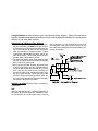
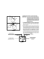
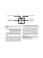
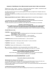
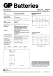
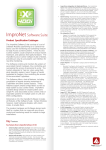
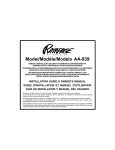
MODEL MA200C
REMOTE CONTROL
MOTORCYCLE ALARM SYSTEM
INSTALLATION GUIDE
AND
OWNERS MANUAL
1
Congratulations on the purchase of your new Audiovox Alarm System. Taking a few minutes to
read this installation and owners guide will provide you with the detailed information concerning all the
features of your new alarm system.
MOUNTING THE SIREN/CONTROL MODULE
1. Choose a location that is away from hot and moving parts considering the Red wire length must be
connected to the to the positive terminal of the battery. Prevent access to the siren as much as possible, by mounting in a hidden location. Typical
locations are underneath the gas tank, seat or exterior body panels. Avoid areas which are subjected to water, engine heat or grease.
2. The internal tilt sensor will be most sensitive when
the siren is oriented so that it is pointed toward the
front or rear of the motorcycle.
3. Once you have selected a location, inspect the area
to ensure that drilling the two required holes to
mount the bracket will not penetrate wiring or fluid
lines. Drill two 1/8" holes into the mounting surface on the motor cycle. Attach the bracket using
the two screws provided. Mount the siren to the
bracket using the two screws provided. Point the
siren horn (front) downward or forward for the greatest volume in the event of an alarm.
use an alternate +12 volt constant source such as
the fuse panel or the ignition switch. Be sure to wire
the 1 Amp fuse (included) as close to the battery connection as possible.
WIRING THE SIREN (Refer to Figure 1 Overall Wiring Diagram)
RED:
Using the attached wire lug, connect the Red wire of
the siren to the positive terminal of the battery. If you
are familiar with your motorcycle's wiring, you may
2
BLACK (LONG):
Using the attached wire lug, connect the Black (long)
wire of the siren to the negative terminal of the battery or
a good ground source.
ORANGE:
This wire is used to connect the alarm system to the
motorcycle's ignition system Refer to Figure 2. This
wire must be connected for the emergency override to
function properly in case the transmitter is lost or stolen. When connected to the ignition switch, the wire is
connected as is. The wire contains a series resistor.
The resistor will get hot of an attempt is made to steal
the motorcycle, so make sure it is not located near lowtemperature material.
BLACK (SHORT):
Stretch the short Black antenna wire as long as possible, avoiding metal contact if possible. This is the antenna wire for the alarm system; route it as high as
possible!
BROWN/BLACK:
This wire is used when an additional horn is connected
to the alarm system. To connect an additional horn, a
relay is required (included in the kit). The relay may be
used as a horn, park light or starter kill. The relay, whenever possible, should be protected from water, engine
heat or grease. NOTE: Additional relays are available as part #AS-9256. Refer to Figure 4 and the accompanying instructions for connecting the horn relay
feature.
ORANGE FROM ALARM
RESISTOR
TO MOTORCYCLE
IGNITION CIRCUIT
FIGURE 2
This wire can also be connected to disable the starter
or ignition. To disable a circuit on the motorcycle, a relay is required (included in the kit). The relay may be
used as a horn, park light or starter kill. The relay, whenever possible, should be protected from water, engine
heat or grease. NOTE: Additional relays are available as part #AS-9256. Additionally, the wire must be
cut to remove the series resistor. The wire will then be
connected to the optional relay. Refer to Figure 5.
WHITE:
This wire is used to connect the alarm system to the
motorcycle's turn signal/running lights. This feature requires a relay (included in the kit). The relay may be
used as a horn, park light or starter kill. The relay, whenever possible, should be protected from water, engine
heat or grease. The relay should be mounted as near to
the lights as possible. NOTE: Additional relays are
available as part #AS-9256. Refer to Figure 6 for relay
connections.
MOUNTING A RELAY
To mount a relay:
1. Screw the relay to the mounting surface, using a sheet
metal screw through the hole in the relay mounting tab.
2. Secure the relay to an existing wire harness or other
component using cable ties. Refer to Figure 3.
3
CONNECTING THE RELAY (HORN FEATURE)
IMPORTANT! The relay has been shipped with the
BLACK wire loaded into terminal 87a
of the Relay Socket. The wire must
be removed from this location and
placed into the outer terminal of the
Relay Harness 87.
1. Connect the ORANGE wire from the relay harness
to the BROWN/BLACK wire from the main harness.
Be sure to insulate this splice with electrical tape.
Refer to Figure 4.
2. Gain access to the wires coming from the back of
the horn. Beep the horn and locate the wire that
changes polarity when the horn beeps. If the voltage
goes low when beeping, then the horn is switched
by a ground signal. If the voltage goes high when
beeping, then the horn is switched by +12 volts.
Connect the BLACK wire from the relay socket to
this wire, and insulate the connection with electrical
tape. Connect the WHITE/BLACK wire to ground or
+12V as required by the horn.
SHEET METAL
RELAY
RELAY
WIRE TIE TO EXISTING
FIGURE 3
To + or - as
required by Horn
Fuse if positive
To Horn
White/Black
Black
30
85
86
To fused 12V
constant source
87a
87
FIGURE 4
4
To Brown/Black
wire of siren
Orange
module
3. Locate the wire coming from the starter switch that
measures + 12 volts on the logic probe when the
starter motor is cranking, and measures 0 volts
when the key is switched to the "OFF" position. Cut
this wire and try to start the vehicle to verify that the
starter motor will not engage. You may also
interrupt the ignition circuit of the motorcycle if an
electric start wire is not available.
Connect the WHITE/BLACK stripe wire from the
relay harness to one side of the cut wire, and
connect the BLACK wire to the other side of the cut
wire.
CAUTION: Be sure these wires are securely connected, and properly insulated. If this
connection separates, the motorcycle
will not start or run, even when using the
ignition key.
CONNECTING THE RELAY (STARTER/IGNITION)
IMPORTANT ! When using the relay to disable the
starter, leave the BLACK wire in terminal 87a of the relay connector in
the location shown in the Figure 5.
1. Connect the ORANGE wire from the relay harness
to the ORANGE wire from the siren harness. Be
sure to insulate this splice with electrical tape.
Refer to Figure 5. Be certain to remove the series
resistor before connecting the relay.
2. Gain access to the wires coming from the ignition
switch. Connect the RED wire from the relay
harness to the wire from the ignition switch that
measures + 12 volts when the key is switched to
the "ON and START" positions, and measures 0
volts when the key is switched to the "OFF" position. Be sure to insulate this connection with
electrical tape.
To starter or ignition
wire from key
Cut
To Start solenoid
or ignition
X
White/Black
Black
30
85
86
To +12V in run
and crank
87a
87
FIGURE 5
5
Orange
To Orange on
MA200
To Bike Harness
To Head Lamp
Black
White/Black
30
85
86
To fused 12V
constant source
87a
Orange
To White
wire of siren
module
87
FIGURE 6
connection with electrical tape. Connect the WHITE/
BLACK wire to the other side of the headlight wire.
3. Connect both the RED wire from the relay socket
and the WHITE/BLACK stripe wire from the relay
socket to a + 12 volt battery fused wire (minimum 15
Amp fuse) in the motorcycle. These wires can be
connected to the positive battery terminal, however
when connecting them to the positive battery terminal, you must add an in line fuse of at least 15 Amps.
Connect one side of the fuse to the positive battery
terminal, and the other side of the fuse to the RED
and WHITE/BLACK stripe wires from the relay
connector.
PROGRAMMING THE KEYCHAIN TRANSMITTERS:
To Program the Transmitters:
1. Disarm the system by the manual override method or
by a pre-programmed transmitter
CONNECTING THE RELAY (HEAD LAMP FLASH
FEATURE)
IMPORTANT! When using the relay to flash the
vehicle’s parking lights, unload the
BLACK wire from terminal 87A of
the relay harness and load it into
terminal 87. Refer to Figure 6.
1. Connect the ORANGE wire from the relay harness
to the WHITE wire from the main harness. Be sure
to insulate this splice with electrical tape. Refer to
Figure 6.
2. Gain access to the wires coming from the back of
the head lamp socket. Switch the head lamp on,
and locate the wire that measures + 12 volts on the
logic probe. Switch the head lamp off, and verify that
this wire now measures 0 volts. Cut this wire in half.
Connect the BLACK wire from the relay socket to
the headlight side of this wire and insulate the
6
2. Turn the ignition "ON" then "OFF" 5 times. The
system will sound a long chirp to confirm entry into the
program mode.
3. Press the "LEFT" button of each transmitter to be
programed (up to Two Transmitters). The siren will
chirp to confirm each transmitter is now programmed.
4. Turn the ignition "ON" then "OFF" to exit the program
mode. The siren will sound a long chirp to confirm the
exit from the program mode.
bracket and securing the bracket to the motorcycle, are
securely tightened.
To adjust the shock sensor:
1. Disarm the system; then press both buttons on the
transmitter simultaneously for 3 seconds. The siren
will sound a long chirp.
2. Press button one on the transmitter to enter the
sensitivity programming mode. Pressing button one
will allow the user to scroll through the four sensitivity
settings. The sensitivity setting will be indicated by
the number of chirps.
a. 1 Chirp = Least Sensitivity
b. 2 Chirps = Intermediate Low Sensitivity
c. 3 Chirps = Intermediate High Sensitivity
(Factory Preset)
d. 4 Chirps = Most Sensitivity
3. To exit the sensitivity setting selection process, press
button two for one second. The siren will sound.
4. Firmly strike the seat of the motorcycle with a closed
fist, considering the amount of force required to vibrate
the motorcycle or change the tilt angle of the bike. (Lift
the bike off the side kick stand).
CAUTION: Never perform this test on the
motorcycle's windscreen, as you may
break it.
5. If the alarm did not sound, the sensitivity setting will
need to be increased. Repeat steps 1, 2 and 3.
6. Repeat this procedure until a firm strike causes the
alarm to sound the warning (siren will sound for 3
seconds and then stop).
Final Touches
If there are any wires from the main harness that you did
you not connect, simply because you did not wish to
activate a particular feature, you should either insulate
the ends of these wires with electrical tape, and tie them
where they cannot be damaged.
ADJUSTING THE SENSITIVITY OF THE SHOCK/TILT
SENSOR
The purpose of a shock detector is to sense strong
impacts to the motorcycle or body panels, but ignore light
bumps. Also the alarm is designed to sense the tilt angle
of motorcycle which prevents the motorcycle from being
moved while the alarm system is armed.
IMPORTANT! Setting the sensitivity of the shock
sensor too high will cause false
alarms. A substantial amount of
force is required to cause damage to
the motorcycle and the shock sensor
should be set accordingly.
Before proceeding with the adjustment, make sure that
all screws securing the siren control module to the
7
NOTE: If the alarm issues three warnings within 15
seconds, the siren will sound a regular alarm
tone which lasts for 30 seconds. After 30
seconds, the siren will automatically stop
and the alarm will arm itself.
alarm cycle. At the end of the cycle, the alarm will
re-arm itself, and resume monitoring the motorcycle.
Disarming the System
1. When you return to the motorcycle, press and
release button 2 on the keychain transmitter. The
system will respond with two chirps or horn sounds
[ two flashes ].
2. If the optional relay was installed to disable the
vehicle’s starter or ignition, the function is deactivated and the motorcycle's starter or ignition is
operational.
Disarming After an Intrusion
When disarming, if the system responds with four
chirps and three light flashes , you are being alerted
to the fact that the alarm was triggered during your
absence. Check the motorcycle for damage before
proceeding.
Disarming While Sounding
To disarm the system while it is sounding, Press and
Hold button #2 until the siren stops sounding.
Remote Panic Operation
The alarm can be activated via the keychain transmitter to draw attention to your vehicle during an emergency situation.
OPERATING THE SYSTEM
Operation of the system is described in this section.
Sounds that can be produced by the alarm system
will consist of siren chirp tones or sounds from the
motorcycle horn (optional relay). The equivalent sounds
are shown in parenthesis. Also if an additional optional
relay was included in the package and used to flash
the parking lights, the parking light indications will be
shown in brackets [ ].
Arming the System
1. Press and release the 1 button on the keychain
transmitter. The system will respond with one
single siren chirp or horn sound [ one flash ].
2. If the optional relay was installed to disable the
vehicle’s starter or ignition, then any unauthorized
attempt to start or drive the motorcycle will be
prevented.
3. Any light impact or slight movement to the motorcycle will cause the system to immediately sound
the warning chirps (3 second chirp), discouraging
any further attempts to tamper with the motorcycle.
4. Continued movement to the motorcycle will cause
the system to trigger for the complete 30 second
8
To activate the panic feature:
1. Press and hold button 1 on the keychain transmitter
for 3 seconds.
2. The alarm will sound, and continue to sound for 30
seconds.
3. To silence the alarm before the 30-second shutdown, press and hold button #2 on the keychain
transmitter.
To use the Override Function:
1.Insert the key into the ignition switch.
2.Turn the ignition switch to the "ON" and "OFF" positions
five times within 20 seconds. Each of the five "ON" and
"OFF" position changes must be longer than 0.3 second.
When the last "OFF" position has been achieved, the
system will disarm.
WARNING: In most areas, it is illegal to activate the
alarm while the motorcycle is moving.
For the safety of your passengers and
other motorists, do not activate the alarm
while your motorcycle is in motion.
Override Function Operation:
The override function is provided in the event of an
emergency; a lost or a malfunctioning transmitter. The
override function allows the user to disarm the system.
NOTE: The override function requires the orange
wire to be connected to the optional relay or
ignition circuit of the motorcycle.
9
REPLACEMENT PARTS
Replacing the Transmitter Battery
The keychain transmitters have a small, red LED
visible through the top cover. This LED can be used to
indicate battery condition. You will also notice a
decrease in effective transmitter range as the battery
deteriorates.
The replacement battery must be a 12 volt type GP27A
or equivalent.
Relay
Transmitter Battery
To replace the transmitter battery:
1. Remove the small phillips head screw(s) from the
bottom of the transmitter, and carefully pry the top
cover (button side) away from the transmitter.
2. Remove the discharged battery, making note of the
orientation of the + and - contacts, and dispose of
properly.
3. Install the new battery, taking care to place the +
and - contacts in the correct position.
4. Replace the transmitter cover, taking care not to
damage the LED or switches on the circuit board.
5. Replace the small phillips head screw(s) through
the bottom of the transmitter.
10
AS9256
GP27A
TROUBLESHOOTING:
3. Verify that the 1 Amp fuse in the red wire from the
siren control module is in good condition. Replace
it if it is blown.
4. Verify that the connections of the red and black
wires have been made according to the wiring
section of this manual.
Symptom: The Transmitters will not program to the
control module.
Check:
1. Verify that the 1 Amp fuse in the red wire from the
siren control module is in good condition. Replace
it if it is blown.
2. Verify that the connections of the red and black
wires have been made according to the wiring
section of this manual.
4. The battery in the motorcycle and/or transmitter is
weak or dead. Change or replace the batteries as
needed.
Symptom: The override function will not disarm the
alarm.
Check:
1. The ignition key must be turned "ON" and "OFF"
five times within 20 seconds..
2. Verify the connections of the orange wire.
Symptom: The alarm will not arm and disarm using
the keychain transmitter.
Check:
1. Verify the transmitter battery is in good condition.
Replace the transmitter battery if necessary.
2. Verify that the transmitter is programmed to the
siren control module. Follow the programming instructions in this manual.
11
F o r C u sto m e r S e rvice
V is it O u r W eb site A t
999.audiovox.com
P rod uct In form a tion , P h otos,
FA Q ’s O w n er ’s M a n ua ls
© 2002 Audiovox Electronics Corp., Hauppauge, NY 11788
12
128-6276