1
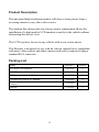
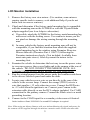
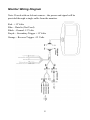
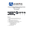
Model: LCDM40A
4.0” LCD Rear Vision Mirror Monitor
Installation Manual
Features
Mirror with built in 4.0” LCD SuperBright Monitor
Low Profile, Slim Design
High Resolution LED Backlit TFT LCD
Built in Speaker
Two video inputs
Auto screen brightness adjustment
Table of Contents
Warnings ...................................................................................... 3
Product Description ..................................................................... 4
Packing List ................................................................................. 4
Monitor Installation ..................................................................... 5
Monitor Wiring Diagram ............................................................. 8
Specifications .............................................................................. 9
Troubleshooting ......................................................................... 10
2
Warnings
The product is intended to assist in safe driving and to allow the driver to
have a broader rear view while the vehicle is in reverse. You, as the
driver, are solely responsible for the safe operation of your vehicle and
the safety of your passengers according to local traffic regulations. Do not
use any features of this system to the extent it distracts you from safe
driving. Your first priority while driving should always be the safe
operation of your vehicle. Audiovox Electronics Corporation cannot
accept any responsibility whatsoever for accidents resulting from failure
to observe these precautions or safety instructions.
1. This product utilizes high voltage. Any unauthorized modifications or
damage to the product may result in electrical shock. Handle all
components with care. Inspect regularly for damage to components
and cabling.
2. You are responsible for ensuring that the installation of this product
does not void or affect the vehicle manufacturer’s warranty.
Audiovox Electronics Corporation or its subsidiaries are not liable in
full or in part for improper installation resulting in loss or damage to
your property, or for voiding all or part of the vehicle manufacturer’s
warranty.
3. Do not apply excessive force to any of the components contained
within this kit. Excessive force used before, during or after
installation that results in a damaged or non-functional part will void
all warranties.
4. Please follow the procedures in this installation manual. Improper
installation or modification of this product will void all warranties.
3
Product Description
This advanced high resolution monitor will show a clear picture from a
reversing camera or any other video source.
The modern thin design and easy factory mirror replacement allows the
installation of a high quality LCD monitor securely in the vehicle without
obstructing the drivers view.
The LCD is perfect for use in any vehicle with a rear vision mirror
This Monitor is designed for use with an Advent camera but is compatible
with most video sources and other cameras and can be connected using a
standard RCA connector.
Packing List
Parts
Barcode #
Quantity
4.0" Rear View Monitor
30262030
1
2.8M Extension Cable
30262160
1
5M Extension Cable (4-Pin)
30262170
1
S-Video (M) to RCA (F) Adaptor
Mounting Bracket (1 x Flat Tombstone, 1 x Toyota
Adaptor)
Manual
30262410
1
30262060
2
31282020
1
4
LCD Monitor Installation
1. Remove the factory rear view mirror. (Use caution, some mirrors
require specific tools to remove, seek additional help if you do not
know how to remove a mirror).
2. Check and determine if the factory metal mounting lug is compatible
with the mounting arm on the LCDM40 or with the Toyota/Honda
adaptor supplied (see Arm Adaptor subsection).
a) If possible, attach the LCDM40 to the factory metal mounting lug
and secure with the locking screw. Use caution to insure you do
not pinch or damage the wiring coming through the mounting
arm.
b) In some vehicles the factory metal mounting arm will not be
compatible, if you find this situation then attach the supplied
metal mounting lug to the window using Permatex Rearview
Mirror Adhesive (Permatex Part # 11067-2) following the
Permatex instructions closely. (Not included, Available from
most auto parts stores). After dry mount the mirror to the
mounting foot.
3. Examine the vehicle to determine the best way to run the power wires
to: accessory power, the reverse lights and to the camera at the rear of
the vehicle. DO NOT CONNECT THE MIRROR UNTIL ALL
CONNECTIONS HAVE BEEN MADE TO THE HARNESS.
4. Run the wiring harness from the mirror under the headliner and down
to the drivers side kick panel and under the dash.
5. Locate your vehicles reverse wire or run directly to the rear of the
vehicle to the reverse lamp. Connect the orange (TRG1) wire to a
wire that supplies +12 volts when in reverse. Connect the RED wire
to +12 volts when the ignition is on. Connect your Camera to the
extension cable directly or use the RCA adapter included. Use CAM1
connection for the primary camera. Connect the Black wire to a metal
grounding location.
6. Connect to the CAM1 input for a secondary video source if desired.
Order Audiovox Part# 30262410 if a second RCA adapter is required.
Note: When using an Advent Camera with your Advent Monitor the signal and power for
the camera will be supplied through the monitor extension cable. Please also note that
5
when equipped with a microphone the audio will be heard on the speaker built into the
mirror housing.
7. Follow the installation and wiring instructions for the camera you are
using.
8. Connect the LCDM40 Monitor to the harness.
9. Power up and adjust on screen settings. In order to see an image you
must be in Reverse gear.
NOTE: To adjust monitor settings press the MENU button on the bottom of the mirror to
scroll through options. Use the + and – buttons to make adjustments as needed.
Arm Adaptor
Note: Used for installation in certain Toyota and Honda vehicles.
If your vehicle has this
mount on the windscreen:
Then use this mounting
block:
Following this installation procedure:
6
Wiring the Camera to the Vehicle’s Reverse Lamp
1. Locate the reverse lamp in the tail light assembly.
2. Using the tap connector supplied, perform the following steps:
a) Place the un-stripped positive lead from the tail lamp in the run
channel, which runs completely through the connector.
b) Insert the un-stripped red power wire from the camera
completely into the other channel in the connector.
c) Make the connection between the wires by crimping down the
metal connector with a pair of pliers, making sure the metal is
flush with the plastic insulator.
d) Close the top plastic hinged cover until latched.
3. Attach the black wire to the ground (negative).
4. Repeat the above steps for the red wire.
7
Monitor Wiring Diagram
Note: If used with an Advent camera – the power and signal will be
provided through a single cable from the monitor.
Red - +12 Volts
Blue – Data In (Not Used)
Black – Ground -12 Volts
Purple – Secondary Trigger +12 Volts
Orange – Reverse Trigger +12 Volts
8
Specifications
1.
2.
3.
4.
5.
6.
Voltage: DC12V
Power: 5w
Signal System: Switchable
LCD Viewing Angle: 170 degrees
Image Display: Selectable Normal/Reverse Image
Adjustable Mounting Angle
9
Troubleshooting
Symptom
No power to the monitor
No image from backup camera
when vehicle placed in reverse
Image is mirrored or requires
adjustment
Sound can not be heard from
Advent camera
Solution
1. Check that reverse power is
attached to orange wire.
2. Check that accessory power is
attached to red wire
3. Check that black wire is
attached to vehicle body
(ground)
4. Check fuse and if blown
ONLY replace with a fuse of
the same rating.
1. Check that camera is
functioning correctly
2. Check that orange wire is
attached to reverse power.
3. Check that backup camera is
attached to input CAM1.
1. All settings are adjusted by
pressing on the MENU button.
1. Increase volume through
MENU button.
2. Ensure Camera is connected
using supplied extension cable
cable.
10