1
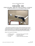
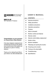
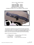
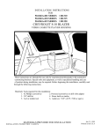
INSTALLATION INSTRUCTIONS
FOR
50-0311x-015 SERIES 1181337
GRAND CARAVAN
OVERHEAD CONSOLE for use with FLIPDOWN VIDEO SYSTEM
These instructions are intended for use only by experienced professionals in the automotive
customizing business. Special tools and equipment, as well as specialized handling and care
of product during installation, may be required. Before beginning this installation, carefully read
through the following instructions. Use extreme care when cutting headliner material.
Check for wiring or other componentry above headliner material. Cut only where indicated.
Materials/ Tools required for this installation:
1. #2 Phillips screwdriver
2. Powered screwdriver or drill with adapter
3. Awl or similar tool
4. Razor knife or similar
5. 18 GA wire 4' - 6'
6. Test light
7. Audiovox Series 640/650 Video Module
NOT FOR VEHICLES EQUIPPED WITH SUN ROOF.
INSTALLATION INSTRUCTION # 44-0047A
Nov. 8, 1999
Printed in the U.S.A
MATERIALS PROVIDED FOR INSTALLATION:
ITEM
Description
QTY
1
SCREW, # 8 X 9/16" PWH
4
2
SCREW, 6-32 X 3/4" PPH
6
3
WASHER, 3.5 mm
4
4
SCREW, # 8 X 1 1/2" PWH
1
5
SCREW, # 6 X 1/2" PFH
2
6
MOUNTING BRACKET
1
7
CONSOLE
1
8
SPEAKER GRILLE
1
9
COVER PLATE
1
10
COVER PLATE DECAL
1
Nov. 8, 1999
Printed in the U.S.A.
INSTALLATION INSTRUCTION # 44-0047A
2
I. PREPARATION OF VEHICLE INTERIOR
1. Remove and retain (3) three screws which secure
dome light in place. See Figure 1.
2. Disconnect wiring and lay light in a safe place.
FIGURE 1
3. Using O.E. console as a reference, carefully
measure and trim headliner as shown. Caution:
Before cutting headliner material, check for
wiring or other componentry above headliner.
Cut only where indicated. DO NOT OVERCUT
HEADLINER. Make sure that the 7 1/2" cut is
centered left to right in vehicle.
See Figure 2.
4. If speaker upgrade kit was purchased, trim these (*)
locations. See Figure 2.
FIGURE 2
5. Construct a jumper harness that will connect the
vehicle’s dome light wires to the lights in video
system. Connect the white wire from video system
to the O.E. pink/blue wire. Connect the black wire
from video system to the chassis ground.
See Figure 3.
6. Using a test light, check function of lights.
7. Install O.E. dome light in original manner.
FIGURE 3
3
8. Install and route all video and audio cables, and any
other added component requirements to their
respective places in the vehicle. Refer to component
installation instructions for wiring diagrams. The
suggested routing of the video system cable is as
follows: Above the headliner from video system
rearward to the C-pillar. Down the C-pillar to the
floor. Route the power lead to a fused accessory
controlled source. Connect the ground lead to the
vehicle chassis. Route the remaining wiring (RCA
plugs, Remote Sensor extension, etc.) to the VCP
location. See Figure 4. Connect per instructions
included with the video system. If video system if to
be used as a television, install an appropriate antenna
per instructions included with the antenna.
FIGURE 4
9. Install console mounting bracket (item 6 pg 2)
over O.E. bracket on roof brace. Align bend in
bracket with edge of O.E. brace. Secure bracket
using (4) four # 8 x 9/16" screws (item 1 pg 2).
See Figure 5.
FIGURE 5
II. INSTALLATION OF CONSOLE
IF SPEAKER UPGRADE KIT WAS PURCHASED, INSTALL PER INSTRUCTIONS PROVIDED.
10. Raise console (item 7 pg 2) into approximate
position against headliner. Loosely install using (2)
two 6-32 X 3/4" screws (item 2 pg 2) through the
smaller holes in bracket on console into threaded
clips on mounting bracket. See Fig. 6.
11. Using a scribe or similar tool, align hole in rear of
console with slot in mounting bracket. Loosely
secure rear of console using (1) # 8 X 1 1/2" screw
(item 4 pg 2). Make sure console is straight then
tighten (2) two 6-32 screws previously installed.
See Figure 6.
FIGURE 6
4
12. Release video screen from locked position. Lower
video screen to viewing position for access to
mounting locations in top of video system
housing.
13. Raise video system into approximate position and
connect all wiring to components. Connect wiring
and cabling to video system per instructions
included with video system.
14. Check function of all components and lights. See
operating instructions for video system operations
check. For further assistance, refer to the video
system manual for the technical support phone
number listed for your area.
FIGURE 7
15. Insert video system into opening in console. Note: Make sure wires do not get pinched between video
system and console. Align holes in housing with clips in mounting bracket. Secure using (4) four 6-32 x
3/4" screws (item 2 pg 2) and (4) four 3.5 mm washers (item 3 pg 2). See Figure 7.
Caution: Do not overtighten screws.
16. Tighten screw previously installed to secure rear of
console to headliner. Caution: Do not overtighten
screws or damage to vehicle roof may occur.
17. Raise video screen into locked position.
18. Install speaker grille (item 8 pg 2). Align clips in grille
with holes in console and press firmly.
See Figure 8.
19. If speaker upgrade kit was not installed, install cover
plate (item 9 pg 2) at front of console and secure
using (2) two # 6 X 1/2" screws (item 5 pg 2 ).
20. Install cover plate decal (item 10 pg ).
FIGURE 8
5