1
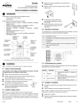
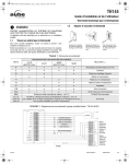
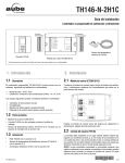
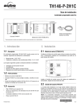
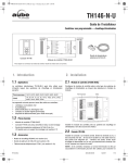
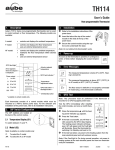
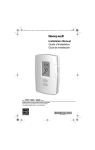
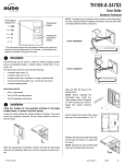
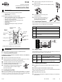
TH149
n
Loosen the locking screw (the screw cannot be completely removed).
Electronic Thermostat
for Heat Pump and HVAC Systems
o
Detach the front module from the back plate by pulling
the bottom part.
p
If necessary, bore the mounting holes
and insert anchors.
q
Pass the wires through the opening of
the back plate and fix the plate to the
wall using the screws provided.
Installation and User Guide
n
1.
Introduction
The TH149 thermostat is used for the following systems:
•
•
Heat pump (1H1C and 2H1C)
HVAC (1H1C)
The thermostat incorporates the following functions:
•
•
•
•
•
•
•
•
System mode selection: heat, cool, auxiliary heat and off
Fan mode selection: automatic or on (continuous)
Emergency heat and fault LEDs
Activation indicators (heat, cool, and auxiliary heat)
Temperature display in °C or °F
Backlit display
Programmable heating and cooling cycle lengths
Keypad lock
Setpoint
indicator
Emergency heat
indicator
2.3 Connecting the Thermostat
The connection of the new thermostat should be similar to that of the old thermostat; however, it can vary depending on the installation.
R; C
Fault
indicator
Fan mode
selector
Temperature
display
W
Heater. This connection is not required for HP-1H1C.
Y
Compressor
G
Fan
O/B
Auxiliary heat
is On *
Cooling is On
Power; 24 VAC
L
Reversing valve (see section 2.4). This connection is not required
for HVAC-1H1C.
Fault
System mode
selector
Heating is On
Temperature adjustment buttons
* Auxiliary heat is available only for 2H1C systems.
o
Installation
2.
Note: The installation must be performed by a qualified electrician.
2.1 Removing the Old Thermostat
IN ORDER TO AVOID ANY RISK OF ELECTRIC SHOCK, CUT POWER TO
THE HEATING SYSTEM.
n
o
2.4 Jumper settings
The jumpers (JP1 and JP2), on the back of the front module, are used to configure the thermostat according to your system type:
Jumper
Parameter
Remove the old thermostat to access the wires.
JP1
System
Identify and label each wire (with the corresponding letter on the old thermostat terminals) and remove them from the terminals.
JP2
Reversing
valve
p
q
If necessary, strip the end of each wire (maximum of 6 mm).
r
If the opening in the wall is too big, insulate it using
a non-flammable material to avoid air draughts
behind the thermostat.
If necessary, wrap the wires around a pencil to prevent them from falling into the wall cavity.
2.2 Installing the Back Plate
Note: For a new installation, choose a location approximately 1.5 m (5 feet)
above the floor and on an inside wall. Avoid draughty areas (top of staircase,
air outlet, etc.) or dead air spots (behind doors). Do not install the thermostat
on a wall concealing air ducts nor expose it to direct sunlight.
TH149
Settings
•
Heat pump (HP position - default)
•
HVAC (CN position)
•
Activated in cool mode (O position - default)
•
Activated in heat mode (B position)
2.5 Completing the Installation
n
Reinstall the front module onto the back plate and tighten the locking
screw.
o
Place the system mode selector switch to OFF.
Note: Leave the switch to OFF until you have verified that the thermostat is
properly configured (see section 3).
p
q
Apply power back to the system.
Ensure that the thermostat is configured according to your system type
(see section 3).
400-149-000-B
10/5/05
1/2
p
3.
Configuration Menu
A switch on the back of the front module can be used to lock the setpoint.
The configuration parameters appear in the order shown below.
PARAMETERS
Temperature display
Heating cycles per hour
1
Cooling cycles per hour 1
DEFAULT
OPTIONS
°C
°C or °F
4
2, 3, 4, 5 or 6 2
4
2, 3, 4, 5 or 6 2
System type
2H
2H (2H1C) or 1H (1H1C)
1H1C type 3
HP
HP (Heat Pump) or Cn (HVAC)
1
When either the heating or the cooling parameter is displayed, use the
mode selector switch to toggle between the two parameters.
2
The corresponding cycle lengths are: 2 = 30 min., 3 = 20 min.,
4 = 15 min., 5 = 12 min., 6 = 10 min.
3
This parameter appears only if you select 1H1C for the system type.
To access the configuration menu, press and hold both temperature
adjustment buttons for more than 3 seconds.
o
To go to the next parameter, once in the menu, press both temperature
adjustment buttons for more than 2 seconds.
p
To modify the displayed parameter, press one of the temperature adjustment buttons.
You will exit the configuration menu at the end of the menu.
Note: The settings are not erased during a power outage.
q
Operation
4.
4.1 System Mode
Use the system mode selector switch to place the system in heat
mode, cool mode, emergency heat (E.H.) mode, or off.
Note: Emergency heat mode is not available on 1H1C systems.
For these systems, placing the selector on E.H. is the same as
placing it on Off.
Auxiliary Heat
Only 2H1C systems are equipped with auxiliary heat. The auxiliary heat is
used in the following conditions:
•
When the setpoint is not attained after a 15-minute delay following the
compressor activation. After the delay, the auxiliary heating is used along
with the compressor.
•
When the thermostat is placed in emergency heating (E.H.). In this mode,
only the auxiliary heat is used.
4.2 Fan Mode
Use the fan mode selector switch to place the fan in automatic
mode (AUTO) or continuous mode (ON).
Note: This switch is not functional if the fan is not connected to
the thermostat.
AUTO
ON
The fan operates only when heating or cooling is activated.
The fan operates continuously.
4.3 Viewing and Setting the Temperature
The actual temperature is normally displayed. To view the setpoint, press
once on one of the temperature adjustment buttons. The setpoint is displayed
for 5 seconds and is indicated by the
icon display. To change the setpoint,
press the appropriate temperature adjustment button during the setpoint display.
4.4 Backlight
The display illuminates for 12 seconds when either of the temperature adjustment buttons is pressed.
TH149
n
Remove the front module from the
back plate to access the switch.
o
Place the switch (S1) to the I position.
p
Reinstall the front module.
r
n
q
4.5 Setpoint Lock
5.
Technical Specifications
Power supply: 24 VAC
Maximum load: 1.5 A per output @ 24 VAC
Setpoint range (heat): 5 to 28°C (41 to 82°F)
Setpoint range (cool): 15 to 35°C (59 to 95°F)
Setpoint increment: ± 0.5°C (1°F)
Display range: -5 to 50°C (23 to 122°F)
Display resolution: 0.5°C (1°F)
Short-cycle protection: 2 minutes
Storage temperature: -20 to 50°C (-2 to 122°F)
Dimensions: 79 mm x 81 mm x 25 mm (3.1 in. x 3.2 in. x 1.0 in.)
s
6.
Warranty
Aube warrants this product, excluding battery, to be free from defects in the
workmanship or materials, under normal use and service, for a period of three (3)
years from the date of purchase by the consumer. If at any time during the warranty
period the product is determined to be defective or malfunctions, Aube shall repair
or replace it (at Aube's option).
If the product is defective,
(i) return it, with a bill of sale or other dated proof of purchase, to the place from
which you purchased it, or
(ii) contact Aube. Aube will make the determination whether the product should be
returned, or whether a replacement product can be sent to you.
This warranty does not cover removal or reinstallation costs. This warranty shall
not apply if it is shown by Aube that the defect or malfunction was caused by
damage which occurred while the product was in the possession of a consumer.
Aube's sole responsibility shall be to repair or replace the product within the terms
stated above. AUBE SHALL NOT BE LIABLE FOR ANY LOSS OR DAMAGE OF
ANY KIND, INCLUDING ANY INCIDENTAL OR CONSEQUENTIAL DAMAGES
RESULTING, DIRECTLY OR INDIRECTLY, FROM ANY BREACH OF ANY
WARRANTY, EXPRESS OR IMPLIED, OR ANY OTHER FAILURE OF THIS
PRODUCT. Some provinces and states do not allow the exclusion or limitation of
incidental or consequential damages, so this limitation may not apply to you.
THIS WARRANTY IS THE ONLY EXPRESS WARRANTY AUBE MAKES ON THIS
PRODUCT. THE DURATION OF ANY IMPLIED WARRANTIES, INCLUDING THE
WARRANTIES OF MERCHANTABILITY AND FITNESS FOR A PARTICULAR
PURPOSE, IS HEREBY LIMITED TO THE THREE-YEAR DURATION OF THIS
WARRANTY. Some provinces and states do not allow limitations on how long an
implied warranty lasts, so the above limitation may not apply to you.
This warranty gives you specific legal rights, and you may have other rights which
vary by province, state or region.
t
7.
Technical Support
For any questions regarding product installation or operation, contact our
technical support team at:
705, Montrichard
Saint-Jean-sur-Richelieu, Quebec
J2X 5K8
Canada
Tel.: (450) 358-4600
Toll-free: 1-800-831-AUBE
Fax: (450) 358-4650
Email: [email protected]
For more information on our products, visit us at
www.aubetech.com
400-149-000-B
10/5/05
2/2