1
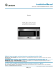
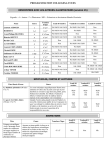
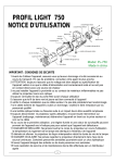
LITERATURE NUMBER MPD 87083 POWER JACK 9 ENGLISH, FRANCAIS RV and Marine Applications •Installation •Operation •Maintenance (et Canada) Effective 11/21/07 SAFETY ALERT SYMBOLS 5. Attach Marine Jack as shown. 6. Route wire lead from motor along trailer tongue to battery. Secure lead to jack housing and trailer frame using cable ties or equivalent. 7. Remove fuse from fuse holder. Connect the wire lead from the jack directly to the positive (+) terminal of the battery. Replace the fuse into the fuse holder. For auxiliary battery, connect lead to auxiliary battery positive (+) terminal so that jack may be used when connected to 115v. For additional wire, use #10 stranded copper wire or larger. 8. After reinstalling fuse, check installation by pressing switch marked “EXT” for jack extension or “RET” to retract the jack. 9. On the Short, Deluxe, Heavy Duty or Marine power jacks, check utility light by moving switch to “ON” or “OFF”. Safety Symbols alerting you to potential personal safety hazards. Obey all safety messages following these symbols. WARNING avoid possible injury or death CAUTION avoid possible injury and/or property damage FOR YOUR SAFETY READ ALL INSTRUCTIONS BEFORE INSTALLATION AND OPERATION Installer: Provide these instructions to the consumer. Consumer: Keep documents for future reference. The Atwood Power Jack is a 12-volt DC motor driven screw jack intended for use on recreational type and marine trailers. Patent # D349800. Jack is used to level trailer or raise and lower coupler for hookup to tow vehicle. CAUTION CAUTION HAND OR FINGER INJURY PERSONAL INJURY/PROPERTY DAMAGE • Hold foot pad near the bottom of the tube, when installing foot pad or caster. • Retract jack fully before towing. • Do not use blocks to increase height of jack. • Use 3500 lb. Heavy Duty Power Jack if you use equalizer bars between the trailer and the tow vehicle. LIGHT WT STANDARD DELUXE HEAVY DUTY 10. Place foot pad, or caster for Marine power jack, over the end of jack, align holes, and place pin through holes. A cotter pin clip goes through the hole in the pin, preventing pin from coming out. OPERATION MARINE SHORT Max. Lifting Cap. LBS 1500 2500 2500 3500 1. To raise or lower jack, press switch marked “EXT” or “RET”. “Extend” and “Retract” refer to the jack, not the trailer. 2. Release switch when jack nears full retraction or full extension to prevent unnecessary wear on motor clutch. a. When jack reaches its maximum extended or retracted length or maximum load, a clicking noise will be heard. This is the overriding clutch built into the motor to prevent overload. Release switch immediately when clicking is heard. If the jack has been over extended or retracted, it may bind. If so, operate with the manual override handle, per STEP 3 below, to break it free. b. When the heavy duty power jack is being retracted, there may be some audible noise, coming from the brake area. This is normal and is due to the high load for which this jack is rated. 3. In case of electrical failure- raise or lower jack as follows: STANDARD & LIGHTWEIGHT POWER JACKS a. Remove top cover by loosening the four screws. b. Remove screws holding motor to mounting plate. c. Lift motor off jack. d. Turn hex drive nut with wrench or optional manual drive handle, part # 87891 (FIG 1-C). e. To reinstall electric motor on jack, rotate hex drive nut so the pin in the hex drive nut aligns with slot in motor drive shaft. f. Tighten hex nut to 25 inch lbs. torque. g. Reinstall motor and fasten with screws. h. Reinstall top cover and fasten with screws. 1000 INSTALLATION 1. Block tires of trailer and securely support trailer tongue. 2. The Atwood RV Power Jack is designed to attach to the top surface of an A-frame type tongue having mounting holes typical of the Atwood A-frame couplers FIG 1. Use coupler installation instructions (MPD 87984) if installing coupler. The Marine Power Jack attaches to the side of a straight tongue trailer. 3. A lower support plate must be used for side support of the RV jack on the lower surface of the A-frame FIG 1. HOLE DIAMETERS: Light Weight 2.02˝ (MIN) 2.09˝ (MAX) Standard / Short / Deluxe / Heavy Duty 2.20˝ 2.28˝ Hole in lower support plate must align with hole in coupler. TO ORDER LOWER SUPPORT PLATE: Light Weight Atwood MPD 80263 Standard / Short / Deluxe / Heavy Duty Atwood MPD 80570 Using 1/8˝ fillet weld, No. E6011 AWS welding rod 1/8˝ diameter, machine amps (AC or DCRP) at 160-180 with 50 volts, weld plate full length on each side to underside of A-frame. The maximum frame height is 6 inches. 4. Place RV jack through holes in coupler and lower support plate, FIG 1-A. Attach with three (3) bolts (3/8˝ dia. x 5/8˝ long, grade 5, (provided) FIG 1-B. NOTE: Torque bolts to 15 foot lbs. minimum /20 foot lbs. max. Note: There must be metal to metal contact between jack and coupler. The three mounting bolts with attached star washers must be used. The star washers are designed to remove paint on the surface of jack flange. The bolts also should remove paint from the mounting holes in coupler. If there is a grounding problem (i.e. no power) check these two surfaces to be sure there is metal to metal contact between jack and coupler. For wiring, see WIRING ILLUSTRATIONS FIG 2 & 3. SHORT, DELUXE OR MARINE JACKS Place manual override handle (FIG 1-C) into alignment tube and engage drive pin. Rotate handle clockwise to raise or counterclockwise to lower the camper. 1 3. Once each year, extend jack as far as possible and clean inner ram tube. Coat tube with light coat of silicone spray lubricant. The Electric Drive Motor Landing Leg system is protected by a 30 amp fuse. If replacement is necessary, replace only with a Buss Type AGC-30 fuse or equivalent, available in automotive supply stores. HEAVY DUTY POWER JACKS Place manual override handle (FIG 1-C) into alignment tube and engage drive pin. Rotate handle counterclockwise to raise or clockwise to lower the camper. MAINTENANCE 1. Before each use, inspect jack tubes and replace if bent or damaged. 2. If wiring is connected to battery terminal, inspect at least twice each year for corrosion. Clean with a solution of baking soda and water, then apply a thin coat of grease. NOTE: The motor ground screw (FIG 1-D) and mounting bolts (FIG 1-B) must be cleaned too if a ground continuity problem occurs. Power Jack TROUBLE SHOOTING GUIDE 9 Effective: 11/21/07 Guides are only intended for use on Atwood products by service technicians who have successfully completed Atwood® training. This guide should be used in conjunction with the appropriate Instruction Manual provided with the product and any applicable Industry Standards. This is not intended to be a complete list. Please direct questions concerning service of Atwood® products to 866-869-3118 before proceeding. hole. If dirty, clean with a 1/4-20 tap. MOTOR CLUTCH ENGAGES Normal if jack leg is at fully ..........None, but let go of switch when you hear retracted or extended position the clutch Worn worm gear ..........................Replace jack ram Dirty inner ram tube ......................Clean ram tube and coat with light coat of silicone spray Bent inner ram ..............................Replace inner ram Clutch faulty ..................................Replace motor Jack at angle ................................Secure mounting bolts and ensure a support plate is used. Excessive tongue weights ............Determine if jack is adequate for tongue weight. ® WARNING PERSONAL INJURY AND/OR PRODUCT DAMAGE • If any of the following conditions develop, the trailer must not be used until proper corrective action is taken. UTILITY LIGHT DOES NOT WORK Loose wires on the ON/OFF ..........Secure wire connection switch Bad light bulb ................................Replace bulb CONDITION WITH SOLUTIONS M O T O R W I L L N O T O P E R AT E No or low voltage ..........................Check battery & electrical connections. Must have minimum of 10 VDC Jack flange not making good ......Clean paint or dirt from coupler frame contact to provide adequate ground with coupler surface Blown fuse ....................................Replace with 30 amp AWG fuse Loose wires on ON/OFF switch ....Secure wire connections ON/OFF switch faulty ....................Replace switch Motor faulty ..................................Replace motor A M P D R AW Range of motor ............................8-45 amps IMPORTANT CAUTION - If equalizer bars are attached to the tow vehicle and the trailer while operating the power tongue jack, you may experience the motor clutching the moment the jack sees load. This will occur because you are lifting both the tongue of the trailer and the rear of the tow vehicle. The 1500 lb. and 2500 lb. acme screw jacks cannot lift this excessive weight. To overcome this excessive weight, you should upgrade to the 3500 lb. power jack. The ball screw mechanism utilized in this jack should allow you to lift this load. POOR GROUND WHEN BUTTON IS PRESSED ON JACK Jack doesn’t operate ....................Inspect motor mounting bolt for Loctite®. If Loctite® found, replace with new 1/4-20 Jack operates only partially up x 3” screw and two lock washers. If bolt or down, or unavailable, clean present bolt and hole Jack runs intermittently with wire buffing wheel. Inspect bolt 2 REPLACEMENT SERVICE PARTS / PIÉCES DÉTACHÉES ITEM LIGHT WT STANDARD SHORT DELUXE HEAVY DUTY MARINE ARTICLE LÉGER STANDARD NORMAL DE LUXE LOURD MARIN 1 87571 87571 87595 87595 87595 87595 2 87060 87060 87057 87057 87057 87057 3 87055 87055 87942 87942 87942 87942 4 86111 86111 86111 86111 86111 86111 5 75367 75367 75625 75625 75625 75625 6 N/A N/A 87916 87916 87916 87916 7 N/A N/A 87108 87108 87108 87108 8 N/A N/A 88002 88002 88002 88002 9 N/A N/A 70298 70298 71132 70298 10 N/A N/A 87941 87941 87941 87941 11 87573 87573 87597 87597 87597 87597 12 N/A N/A 87585 87585 87585 87585 13 N/A N/A 87591 87591 87591 87591 14 87035 87035 87035 87035 87035 87035 15 80237 80512 87489 87500 87559 N/A 16 N/A N/A 87847 87847 87847 87847 17 70229 70229 70667 70667 70667 70667 18 87568 87568 87598 87598 87598 87598 19 N/A N/A 87586 87586 87586 87586 20 87570 87570 87570 87570 87570 87570 21 87327 87327 87327 87327 87327 87327 22 N/A N/A 87599 87599 87599 87599 23 24 N/A 87176 N/A 87176 N/A 87176 N/A 87176 N/A 87176 N/A 87176 25 OPTIONAL OPTIONAL 87891 87891 87891 87891 26 70269 70269 70269 70269 N/A 70269 27 80238 87021 87021 87021 87021 -- 28 87709 87709 87709 87709 70215 87709 29 87077 87077 N/A N/A NA N/A 30 87569 87569 N/A N/A N/A N/A 31 32 87150 84037 DESCRIPTION DESCRIPTION Upper Cover Couvercle supérieur Cover Screw Vis du couvercle Motor Ground Screw / Vis Lock Washer Rondelle de blocage Motor and Terminals Moteur et bornes Cover Tube Tube du couvercle Bevel Gear Kit Pignon conique Gear Housing Cover Couvercle de la boîte de vitesse Drive Pin Goupille d’entraînement Drive Shaft Arbre d’entraînement Lower Cover Couvercle inférieur Wire & Light Bulb* Ampoule électrique* Lens / Lentille Hole Plug Bouchon de l’orifice Standard & Lightweight Power Jack Cric électrique service normal et léger 1 18 5 29 17 20 11 30 15 Jack Hsing & Ram Asy 16˝ trvl Enveloppe du vérin et corps du cric à course de 16 po Washer Support Support de rondelle Pin / Tige Ground Wire Fil de terre Light Switch Commutateur d’éclairage Motor Switch Commutateur du moteur Strain Relief Bushing Bague de bride de cordon Jumper Wire & Fuse Fil de connexion et fusible Fuse▲ / Fusibles▲ Mounting Bolt / Boulon Manual Drive Handle Manette de commande manuelle Cotter Pin Goupille fendue Round Foot Pad Coupelle ronde Clevis Pin Axe de chape Hex Drive Nut Écrou de commande hexagonal Fuse Wire Fil du fusible Bracket / Patte Caster / Roue pivotante 26 28 27 Short, Deluxe, Heavy Duty & Marine Power Jack 1 2 3 4 5 6 7 16 8 17 18 9 19 10 20 11 12 13 21 22 23 14 15 *912 type T5 12 candle power *912 type T5 12 candelas ▲ Buss Type AGC-30 amp fuse ▲Buss type AGC-30 à fusible Cric électrique service court, deluxe et lourd 25 24 Marine Power Jack 31 26 28 32 3 27 POWER JACK WIRING ILLUSTRATIONS 1 Lightweight & Standard RED LEAD FROM MOTOR D Short, Deluxe & Heavy Duty (DELUXE) - RED LEAD (HEAVY DUTY) - YELLOW LEAD FROM MOTOR YELLOW LEAD FROM MOTOR (DELUXE) - YELLOW LEAD (HEAVY DUTY) - RED LEAD FROM MOTOR RED JUMPER FROM FUSE WIRE BLACK GROUND WIRE W/BLACK JUMPER BLACK FUSE WIRE 2 C GROUND TO MOTOR SCREW 3 BLACK WIRE FROM LAMP BASE SPADE CONNECTOR BLACK JUMPER FROM GROUND WIRE BLACK FUSE WIRE W/RED JUMPER GROUND TO MOTOR SCREW AT ASSEMBLY B CRIC ÉLECTRIQUE SCHÉMAS DE CABLAGE Cric Électrique Standard FIL CONDUCTEUR ROUGE DU MOTEUR Cric Électrique De Luxe et Haute Capacité FIL JAUNE (DE LUXE) FIL ROUGE (DE LUXE) FIL JAUNE (DE GRANDE CAPACITÉ ) FIL ROUGE (DE GRANDE CAPACITÉ ) DU MOTEUR DU MOTEUR FIL CONDUCTEUR JAUNE DU MOTEUR A FIL NOIR DU FUSIBLE 2 FIL DE CONNEXION ROUGE DU FIL DU FUSIBLE FIL DE TERRE NOIR AV. FIL DE CONNEXION NOIR 3 FIL DE TERRE À LA VIS DU MOTEUR FIL NOIR DU FUSIBLE FIXÉ AU FIL DE CONNEXION FIL NOIR DE LA BASE DE LA LAMPE CONNECTEUR DE COSSE FIL DE CONNEXION NOIR DU FIL DE TERRE FIL DE TERRE À LA VIS DU MOTEUR À L'ASSEMBLAGE 1 MARINE POWER JACK WIRING ILLUSTRATIONS RED LEAD FROM MOTOR YELLOW LEAD FROM MOTOR RED JUMPER FROM FUSE WIRE 2 RED FUSE WIRE TO VEHICLE WIRING HARNESS BLACK WIRE FROM LAMP BASE SPADE CONNECTOR BLACK JUMPER FROM GROUND WIRE BLACK GROUND TO VEHICLE WIRING HARNESS CRIC ÉLECTRIQUE MARIN SCHÉMA DE CÂBLAGE Attachment Hardware (included) Boulonnerie de fixation (incluse) FIL CONDUCTEUR ROUGE DU MOTEUR FIL CONDUCTEUR JAUNE DU MOTEUR FIL DE CONNEXION ROUGE DU FIL DU FUSIBLE FIL ROUGE DU FUSIBLE AU FAISCEAU DE CÂBLES DU VÉHICULE FIL NOIR DE LA BASE DE LA LAMPE 2 FAISEAU DE CÂBLES NOIR DE LA TERRE AU VÉHICULE CONNECTEUR DE COSSE CONNECTEUR DE COSSE FIL DE CONNEXION NOIR DU FIL DE TERREE 4 ATWOOD POWER JACK LIMITED WARRANTY Atwood Mobile Products warrants to the original owner this product will be free of defects in material and workmanship for a period of two years from the date of purchase. Atwood’s liability hereunder is limited to the replacement of product, repair of product or replacement of product with a reconditioned product, at the discretion of the manufacturer. The warranty is void if the product has been damaged by accident, unreasonable use, neglect, tampering or other causes not arising from defects in material or workmanship. The warranty extends to the original consumer purchaser of the product only, and is subject to the following conditions: 1. For two (2) years commencing with the date of purchase, Atwood will provide the replacement or repair of any Hardware System and Components that are found to be defective by Atwood in material or workmanship. 2. In the event of a warranty claim, the Original Owner must contact the Atwood Consumer Service Department, 1120 North Main, Elkhart, IN 46514, telephone: 866-869-3118, fax: 574-206-9655. Warranty claim service must be performed as approved by the Atwood Consumer Service Department. Warranty replacement hardware systems and components or parts will be furnished freight prepaid, labor cost to repair or replace will be limited to the amount of the original purchase price of the systems and components. The replaced warranty products or parts become the property of Atwood Mobile Products and must be returned to the Atwood Consumer Service Department freight prepaid, unless prior arrangements have been agreed to. 3. This limited warranty is valid only when the product is applied, installed, maintained and operated in accordance with this Atwood Installation, Maintenance and Operating Manual. Any deviation from these recommended specifications must be approved in writing by Atwood. 4. Any implied warranties are limited to the duration of this limited warranty as stated above. Atwood does not assume responsibility for consequential damage or loss, including loss of use of vehicle, loss of time, inconvenience, expense for gasoline, telephone, travel, lodging, loss or damage to personal properties, or loss of revenues. Some states do not allow limitations on how long an implied warranty lasts or limitations on consequential damages, so the above limitations may not apply to you. This limited warranty gives you specific legal rights which may vary from state to state. 7