1
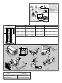
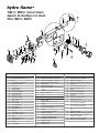
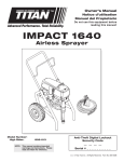
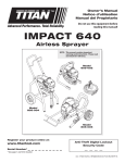
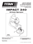
MPD 32072 hydro flame TM 7900-II / 8000-II Series Furnace 9 Technical Installation Manual ENGLISH, FRANCAIS •Installation (et Canada) Effective 1/08 THIS INSTRUCTION MANUAL IS FOR USE BY AN AUTHORIZED SERVICE TECHNICIAN TO INSTALL AN ATWOOD - hydro flame TM INDEX FURNACE. ..............................................................1 ..................................................................1 WEIGHT ........................................................................1 DUCTING CONFIGURATION ................................................................1 MINIMUM CLEARANCE TO FLOORBOARDS, WALLS, & SIMILAR COMBUSTIBLE BUILDING MATERIALS..................................2 SAFETY INFORMATION ................................................................1-2 FURNACE INSTALLATION ..............................................................2-4 CUTOUTS ..................................................................................2 DUCTING ................................................................................2-3 Flexible Ducting ......................................................................2 Venting Chart ........................................................................3 OPTIONAL INSTALLATION - DIRECTIONAL AIR BOX ....................................3 PROPANE GAS CONNECTION ............................................................3 ELECTRICAL CONNECTIONS ..............................................................3 Thermostat Installation ............................................................3 Door Installation ....................................................................3 SYSTEM CHECK TESTS ....................................................................4 PROPANE GAS PRESSURE ..............................................................4 FIGURES 1-8 (INCLUDING DC WIRING DIAGRAM) ..........................................4 REPLACEMENT PARTS LIST & DRAWING ..............................................8 FURNACE SPECIFICATIONS INSTALLER: LEAVE THIS MANUAL WITH THE APPLIANCE. DIMENSIONS CONSUMER: RETAIN THIS MANUAL FOR FUTURE REFERENCE. This furnace design has been certified by the American Gas Association and Canadian Gas Association for installation in recreation vehicles as a MSP Category III furnace. Follow this installation instruction to insure safe operation of the furnace. Failure to install furnace according to this installation instruction nullifies the furnace warranty. SAFETY ALERT SYMBOLS Safety Symbols alerting you to potential personal safety hazards. Obey all safety messages following these symbols. WARNING avoid possible injury or death CAUTION avoid possible injury and/or property damage WARNING: If the information in this manual is not followed exactly, a fire or explosion may result causing property damage, personal injury or loss of life. DUCTING CONFIGURATIONS ONE side duct FRONT — Do not store or use gasoline or other flammable BOTH side ducts vapors and liquids in the vicinity of this or any other appliance. — WHAT TO DO IF YOU SMELL GAS — 79/80 SERIES 80 SERIES ( 8012-II) • Evacuate all persons from vehicle. • Shut off gas supply at gas container or source. • Do not touch any electrical switch, or use any phone or radio in vehicle. • Do not start vehicle’s engine or electric generator. • Contact nearest gas supplier or qualified Service Technician for repairs. • If you cannot reach a gas supplier or qualified Service Technician, contact the nearest fire department. • Do not turn on gas supply until gas leak(s) has been repaired. Installation and service must be performed by a qualified Service Technician, Service Center or gas supplier. 79 SERIES 79 SERIES SPECIFICATIONS # Input BTU/HR Output Capacity BTU/HR Duct Static Pressure 12 Volt Amperage (AMPS) Watts Power Supply (Volt DC) MINIMUM RETURN AIR MODEL 7912-II 12,000 9,160 .20" W.C. 3.4 40.8 12 35 in2 7916-II 16,000 12,160 .10" W.C. 3.4 40.8 12 35 in2 (W.C. = Water Column) 7920-II 8012-II 18,000 12,000 13,680 9,120 .10" W.C. N/A 3.4 1.8 40.8 21.6 12 12 35 in2 35 in2 DIMENSIONS ALL MODEL WIDTH HEIGHT DEPTH Casing Door 8-3/8˝ 9-7/8˝ 11-3/8˝ 11-1/2˝ 20-5/8˝ 1-1/4˝ WEIGHT FURNACE SHIPPING 23 lbs 25 lbs MINIMUM CLEARANCE TO FLOORBOARDS, WALLS & SIMILAR COMBUSTIBLE BUILDING MATERIALS MUST BE PROVIDED THE FULL LENGTH AND WIDTH OF UNIT Top and Sides Extension Box Rear Bottom 1 0˝ 0˝ 0˝ 0˝ TO CASING SPACERS (SCREW HEADS) TO CASING SPACERS (SCREW HEADS) Spacing of 1/4˝ to ducting within 3 feet of furnace must be provided unless UL listed wire bound vinyl ducts are used. All ducting material should be rated for continuous use of 200˚F. NOTE: If zero clearance is maintained from furnace to cabinet structure, a 4˝ x 4˝ air intake cutout must be provided to blower wheel side of furnace at air intake opening. NOTE: Clearances are specifically for plywood or similar building materials surrounding the furnace (i.e. furnace should NOT be located under furniture or in a closet space where clothing or other material could be located.) NOTE: Furnace efficiency rating is a thermal rating determined under continuous operating conditions, independent of any installation. Eff. rate is given at 77% minimum, actual efficiency rating may be higher. *When furnaces are installed to minimum clearances, an additional 16 in2 of return air must be provided to blower side of furnace, or a 2˝ clearance the full length and height on blower side must be maintained. Return air is supplied through openings in furnace grille. The return air passage must be kept clear for furnace to function properly. Refer to MINIMUM CLEARANCE TO FLOORBOARDS, WALLS & SIMILAR COMBUSTIBLE BUILDING MATERIAL. STANDARD FURNACE INSTALLATION General Installation - LOCATION Install extension box and vent cap through an exterior wall. install furnace near tilt-out rooms, slide-outs, doors or other projections that could obstruct furnace exhaust. • Locate furnace near midpoint of coach for single furnace applications. • DO NOT install vent in areas where projections or door openings come within 6˝ of vent tube opening. • DO NOT install furnace in an area where wires, pipes, or other objects will interfere with installation or operation of furnace. • It is not recommended to install furnace on material that restricts return air, such as directly on carpet, or soft material (like vinyl). • If you must install furnace on carpet or soft material, install furnace on cleats, or on a wood or metal panel extending the full width and depth of furnace plus minimum clearances to combustibles. • • DO NOT WARNING CARBON MONOXIDE POISONING Furnace must be installed and vented to these instructions. Improper installation, adjustment, alteration, service or maintenance can cause injury or property damage. • Improper installation location may cause furnace to produce negative pressure, affecting combustion air or venting of other appliances. Installation Procedure ZERO CLEARANCE - AIR INTAKE CUTOUT (FIG 1) • • AIR INTAKE OPENING SIDE OF THE BLOWER WHEEL CUT OUT DIMENSION CABINET WALL CRITICAL INSTALLATION WARNINGS B 3-5/8˝ C 4˝ D 4˝ A 4˝ x 4˝ cabinet cut out must be provided when there is zero clearance between furnace and cabinet structure. install furnace on material that restricts return air, like carpet or any soft material such as vinyl. • DO NOT install where clearance to combustibles cannot be maintained. • DO NOT modify furnace in any way. • DO NOT alter furnace for a positive grounding system. • DO NOT HI-POT furnace unless electronic ignition system (circuit board) has been disconnected. • DO NOT use battery charger to supply power to DC model furnace even when testing. • DO NOT use 120 volt AC current with DC models. • DO NOT use furnace cabinet area as a storage compartment. • DO NOT vent furnace with venting system serving another appliance. • DO NOT vent furnace to an outside enclosed porch area. • DO NOT use for temporary heating of buildings or structures under construction. • Protect building materials from degrading from flue gas exhaust. • Protect furnace electrical components from water. • DO NOT 1. Set aside combustion air box and exhaust tube extensions for installation from outside coach. FURNACE / VENT - CUTOUTS (FIG. 2) A 8-3/8˝ CUT OUT DIMENSION INTERIOR CABINET WALL DO NOT OVERSIZE HOLE B 11-1/4˝ - OVERSIZING CAN RESULT IN WATER LEAKAGE CUT OUT DIMENSION COACH EXTERIOR WALL FOR VENT C 4-7/8˝ D 2-1/2˝ E 1-3/4˝ DUCTING (FIG. 3) Proper duct installation is critical to operation of furnace. When installing ducts, use materials rated for continuous use at 200˚F. Front discharge temperature should not exceed 250˚F. Flexible Ducting System When designing Flexible Duct Systems: • avoid sharp bends or crushed ducts • stretch all ducts and run them directly to outlets, keeping quantity and angles of bends to a minimum - FOLLOW ALL APPLICABLE STATE AND LOCAL CODES IN THE ABSENCE OF LOCAL CODES OR REGULATIONS, REFER TO CURRENT STANDARDS OF: • Recreation Vehicles ANSI 1192/NFPA 1192. • National Fuel Gas Code ANSI Z223.1 /CAN/CGA B149 Installation Codes • Federal Mobile Home Construction & Safety Standard, Title 24 CFR, part 3280, or when this Standard is not applicable, the Standard for Manufactured Home Installations (Manufactured Home Sites, Communities and Set-Ups), ANSI A255.1 and/or CAN/CSA-Z240 MH Series, Mobile Homes. • Ground - National Electrical Code ANSI/NFPA No. 70 and/or CSA C22.1 • Park Trailers ANSI 119.5 USA AND CANADA 2. A variety of vent kits are available to provide the correct venting from furnace to outside of vehicle. To determine VENT LENGTH (V DIM), measure the distance from the back of furnace casing to outside vehicle side wall. For proper vent kit check your V DIM on VENTING CHART. 3. Ducting available: TYPE OF DISCHARGE NOTE: The direct high voltage spark ignition generates a radio frequency that could cause interference with other microprocessor based equipment. Locate equipment at least five feet from furnace location. If this distance cannot be maintained, purchase KIT MPD 37773 (a shielded high voltage lead). WARNING CARBON MONOXIDE POISONING • Properly seal vent cap to side wall to prevent carbon monoxide from entering coach. • DO NOT draw combustion air from living area. DO NOT vent exhaust air into the living area or an enclosed porch. A 2-3/4˝ REMOVE SIDE ONLY duct covers from both sides COMBINATION FRONT & SIDE front discharge cover plate and side duct cover plate FRONT ONLY front discharge cover plate See DUCTING CONFIGURATIONS for covers and their locations. 2 4. Install the furnace through cutout in cabinet area. Secure furnace with two screws FIG 5-A. OPTIONAL - Installation: The 79-II furnace may be installed in a cabinet behind a return air grille FIG 4-I. Door MUST be on furnace. Return air grille must supply a minimum of 35 in2 of open area and be in front of door to furnace. Provide an access opening for service and/or removal of furnace. The furnace must be side ducted (NO front discharge). Secure furnace to floor with one screw FIG 4-J. 5. Remove cover plate from furnace FIG 4-D. To install duct adapters for side discharge models, insert back flange over casing and insert tab into square notch, then twist adapter 180˚ FIG 4-E. 6. Insert furnace into cabinet opening and secure with two screws through holes in control box flanges FIG 5-A. 7. For side duct applications, slide 4˝ flexible ducting material over duct adapters and secure FIG 3. ELECTRICAL CONNECTION WARNING INJURY OR PROPERTY DAMAGE Label all wires before disconnecting for service. Wiring errors can cause improper, dangerous operation. Verify proper operation after servicing. • Disconnect electrical power before servicing. • Conductor Sizing Table - MAX. 10% VOLTAGE DROP - (12 VDC) CURRENT DRAW (AMPS) 3 VENTING GAGE 1. To install extension box FIG 4-C, apply mastic or sealant to back of flanges on box. Slide through outside wall cut out and into furnace air channel. DO NOT FORCE OR BEND PARTS. 2. Apply mastic or sealant to the top and sides of outer edge of vent cap. DO NOT PLUG HOLES. Slide assembly over furnace exhaust tube FIG 4-B, push into wall and secure with two screws. Note that bottom flange is not sealed to allow water drainage. 3. The extension box has no minimum clearance requirement FIG 4-C. 4. The vent outlet shall be installed as to be in the same atmospheric pressure zone as the combustion air intake. No modification of vent system is allowed. 18 16 5 6 7 8 9 10 15 61 96 45 72 36 58 30 48 26 41 23 36 20 32 18 29 12 19 CAUTION PROPERTY DAMAGE • This connection is for low-voltage battery or direct current only. Do not connect to 120- or 240- volts AC. This furnace is designed for negative ground 12 volts DC only. DO NOT attempt to alter furnace for a positive ground system or connect furnace directly to 120 volts AC. Damage to furnace components will occur and warranty will be voided. Use a minimum of 22-18 GA wire to minimize voltage drop. The furnace must be installed so electrical components are protected from water. To make electrical connections: SEE WIRING DIAGRAM FIG 8 1. Remove screw from junction box on right side of furnace FIG 5-B. 2. Route wiring to right side of furnace. 3. Connect red wire FIG 5-C to positive side of power supply. 4. Connect black wire FIG 5-D to grounded side of power supply. 5. Connect white wire from furnace to thermostat FIG 5-E. 6. Connect thermostat wire from thermostat to +12VDC of power supply FIG 5-F. 7. Reinstall junction box cover FIG 4-F. For best performance of furnace when power supply is from a converter equipped with a charging port, wire the converter to furnace parallel with battery. This provides consistent voltage to furnace, increasing component life, filtering power surges and AC spikes FIG 4-G & H. NOTE: All units are supplied with a power switch which when turned off for servicing will remove power through the furnace wiring. Switch must be in ON position for the furnace to operate FIG 5-I. WARNING CARBON MONOXIDE POISONING • 4 MAX. LENGTH OF SAE CONDUCTOR (IN FEET) FROM SOURCE TO DEVICE Properly seal vent system preventing carbon monoxide from entering coach. 5. Install return-air system to ensure negative pressure, created by the circulating blower, does not effect another appliance’s combustion air supply or act to mix products of combustion with circulating air. All appliances in the furnace cabinet must be directly vented outside. (FIG. 7) 1. Remove front door of furnace. 2. Follow shutdown procedure instructions affixed to furnace. 3. Remove sheet metal screw holding circuit board plate to air box. Retain to fasten Air Box Insert to bottom of air box FIG 7-A. 4. Install Air Box Insert into air box (pay attention to the direction you would like warm air diverted). Make sure two holes in Air Box Insert line up with existing holes in air box FIG 7-B. 5. Fasten Air Box Insert to top of air box using a 1/4˝ long #6 sheet metal screw. Fasten bottom of Air Box Insert and circuit board plate to bottom of air box using the screw removed. 6. Follow lighting instructions to place furnace in operation. 7. Replace front door on furnace. DIRECTIONAL AIRBOX INSERT THERMOSTAT INSTALLATION The thermostat is very sensitive. HANDLE WITH CARE AT ALL TIMES. Locate thermostat 48˝ to 54˝ above floor on an INTERIOR wall away from areas of abnormal heat or cold. EXTERIOR wall location must have a 3/4˝ spacer between thermostat and exterior wall. Follow manufacturer’s installation instruction provided with thermostat. When thermostat is not supplied, use a thermostat rated for 12 VDC or 24 VAC min. 1 AMP. PROPANE GAS CONNECTION (FIG. 5) DOOR INSTALLATION Connect gas line to brass fitting on left side of furnace. Be sure all male pipe threads, other than flare fittings, are treated with a sealing compound resistant to the action of propane (LP) gas. DO NOT put sealing compound on flare fittings. Install door by sliding door flange over control box top flange and fastening door at bottom with 1/4 turn fastener. Note: To assure sufficient return air to circulating blower maintain specified clearances. SYSTEM CHECKS WARNING 1. Insert gas line through hole on left side. 2. Connect gas line to brass fitting inside furnace casing immediately ahead of gas control valve FIG 5-B. 3. A 3/8˝ flared fitting connection is provided at gas control valve inlet for gas supply connection to furnace. The gas supply line of furnace must be of adequate size to provide 11˝ W.C. gas pressure. This pressure must be maintained under maximum flow conditions with all gas appliances operating. 4. A 1/8˝ N.P.T. plug is accessible for test gauge connection on gas valve assembly FIG 5-H. 5. Use two wrenches to hold brass fitting and flare nut when tightening gas line to brass fitting. DO NOT twist valve assembly FIG 6. FIRE OR EXPLOSION • Never check for leaks with an open flame. PROPANE GAS PRESSURE TEST The furnace and any individual shut-off valve must be disconnected from gas supply piping system during any pressure testing of system at test pressures of more than 1/2 PSI. Before furnace is connected piping systems must be tested to be leak free. The test must maintain air pressure of at least 6˝ of mercury or 3 PSI for at least 10 minutes. The entire piping system must be maintained within a range of 10-14˝ W.C. with all appliances in operation. Test gas connections for leakage with a leak test solution. 3 NOTE: The ON/OFF switch, located in line with the gas valve, is not used when a combination circuit breaker and ON/OFF switch is used. IMPORTANT Wiring must be replaced with wire rated 105˚C or higher. GROUND 8 ELECTRODE MOTOR Black Red Black White Red LIMIT CIRCUIT BREAKER On/Off Switch Red White VALVE Red Pwr Blw DSI CONTROL NEG White SAIL SWITCH 5179 Yellow +12V DC White Black White Red THERMOSTAT Black Blue High Tension VENT VENTING CHART VENT FM F DIM. M DIM. MAX EXTENSIONS TUBE EXT. SS* ALX SS* AL▼ BOX 24˝ 610 MM 36441 35955 35921 36444 35941 24˝ 610 MM 27-5/8˝ 702 MM 36442 35956 35928 36446 35947 27-5/8˝ 702 MM 31-1/8˝ 791 MM 36443 35957 35930 36448 35951 MIN MAX MIN 0˝ 0 MM 3-5/8˝ 92 MM 20-1/2˝ 521 MM 3-5/8˝ 7-1/8˝ 92 MM 181 MM 7-1/8˝ 10-5/8˝ 181 MM 270 MM EXHAUST KEEP CLEAR FURNACE KEEP CLEAR V VENT KIT NO. CABINET DEPTH V DIM. COACH INTERIOR D (-) Ground Black (-) C E C D D I B A G A B A A B B G C 1 H 3 2 5 A B B A C J G D +12 VDC E -12 VDC F +12 VDC Red 4 I 6 H -12 VDC Black DIAGNOSTIC CHART FAULT Internal Circuit Board Failure Limit switch/Airflow problems Flame Sense Fault Ignition Lockout Fault LED INDICATION Steady on, no flashing 1 flash with 3-second pause 2 flashes with 3-second pause 3 flashes with 3-second pause 4 7 E (+) 12 VDC (+) hydro flame TM 7900-II / 8000-II Series Furnace Appareil de chauffage à air chaud Série 7900-II / 8000-II 29 28 30 8 11 6 12 24 23 5 13 4 3 27 7 2 1 16 26 17 14 18 10 15 30 25 31 9 21 19 20 22 Item # Description of Parts 1 2 3 4 5 6 7 8 9 10 10 11 11 12 12 13 14 15 16 17 18 19 20 21 22 23 Front Door Electronic Ignition Board Valve Front Discharge Cover Plate Electrode Cover Plate Electrode Electrode Gasket Heat Exchanger Burner Plate Gasket Sail Switch (79-II) Sail Switch (80-II) Blower Wheel (79-II) Blower Wheel (80-II) Motor (79-II) Motor (80-II) Combustion Wheel Duct Adapter Duct Cover Plate Air Hose Thermostat -SPECIFY COLOR Limit Switch (L-170) Relay On/Off Circuit Breaker Burner Head Manifold Motor Gasket Item # Description of Parts 24 25 25 26 27 28 29 Motor Spacer Small Burner Air Baffle - SPECIFY RATE Large Burner Air Baffle - SPECIFY RATE Electronic Ignition Mounting Plate Valve Bracket Vent Kit Specify Length Exhaust Tube Assembly - SPECIFY LENGTH & MATERIAL 30 31 Air Box Assembly - SPECIFY LENGTH Orifice - SPECIFY RATE Élément n˚ 1 2 3 4 5 6 7 8 9 10 10 11 11 12 Description des pièces Panneau avant Plaquette d'allumage électronique Soupape Couvercle de l'ouverture d'évacuation avant Couvercle de l'électrode Électrode Joint d'étanchéité de l'électrode Échangeur thermique Joint d'étanchéité de la plaque du brûleur Interrupteur à abattant (79-II) Interrupteur à abattant (80-II) Ventilateur (79-II) Ventilateur (80-II) Moteur (79-II) 8 Élément n˚ Description des pièces 12 13 14 15 16 17 18 19 20 21 22 23 24 25 Moteur (80-II) Ventilateur d'air de combustion Adaptateur de conduit Couvercle d'ouverture de branchement Tuyau à air Thermostat -PRÉCISEZ LA COULEUR Rupteur thermique (L-170) Relais Coupe-circuit marche/arrêt Tête de brûleur (79II/80II) Collecteur Joint d'étanchéité du moteur Entretoise du moteur Petit déflecteur d'air du brûleur - PRÉCISEZ 25 Grand déflecteur d'air du brûleur - PRÉCISEZ 26 Plaque de montage de l'allumage électronique Support de soupape Module d'évacuation - PRÉCISEZ LA LONGUEUR Exhaust Tube Assembly - PRÉCISEZ LA LES CARACTÉRISTIQUES NOMINALES LES CARACTÉRISTIQUES NOMINALES 27 28 29 LONGUEUR ET LE MATÉRIAU 30 31 Boîte à air - PRÉCISEZ LA LONGUEUR Lumière - PRÉCISEZ LE CALIBRE