1
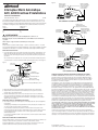
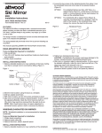
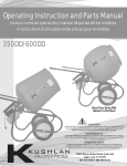
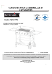
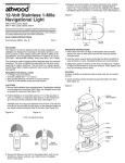
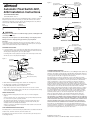
Figure 2
3
®
Fuse (See Pump
Specifications For Size)
72" (183 cm)
Maximum Length
From (+) Terminal
to Fuse Holder
•
Automatic Float Switch 4201,
4202 Installation Instructions
Brown Wire
•
Black Wire
•
–
+
SAVE THESE INSTRUCTIONS
Form Number 69272 Rev. D
03-10
Automatic
Float Switch
Pump
FULLY AUTOMATIC OPERATION
This automatic float switch converts any standard bilge pump to automatic operation.
Pump must operate on 6 to 32 volts D.C. (see chart). The switch can be mounted
separately from the pump; it can also attach to the mounting bracket of any Attwood
V-Series pump—4204, 4206, 4207, 4209, or 4212.
Input
DC Voltage
12
24
32
Maximum
DC Amperages
12
6
4.5
12 Volt Battery
Fuse (See Pump
Specifications for Size)
Attwood
Rocker Switch
(Rear View)
•
72" (183 cm)
Maximum Length
From (+) Terminal
to Fuse Holder
•
Brown Wire
WARNING:
•
This product is not intended for use with AC voltage systems, including AC-to-DC
converted power sources.
Always use the fuse amperage rating specified for your pump model.
•
Always disconnect the power source when installing or servicing this product.
Automatic
Float Switch
1. Locate float switch as close as possible to the bilge pump. Switch should never be
mounted at lower level than pump. Switch mounting surface should be at least level
with the pump mounting surface, up to 1/4" (6mm) higher.
Fuse (See Pump
Specifications for Size)
Two-Terminal, “On-Off” Type
Switch Can Be Attwood
Rocker, Push-Pull, or
Toggle Type
•
•
•
•
Brown Wire
•
Cover
•
72" (183 cm)
Maximum Length
From (+) Terminal
to Fuse Holder
Black Wire
•
•
#8 Stainless
Steel Screws
12 Volt Battery
Pump
If mounting with a V-Series pump, the front tabs on the switch may be interlocked
with the rear slots on the pump bracket. Figure 1
Figure 1
–
“ON/OFF/AUTO” OPERATION
Important:
Do not allow sealants containing acetic acid—such as silicone rubber—to come in
contact with the switch housing. They can damage and crack the plastic, causing the
switch to fail. Sealants with acetic acid smell like vinegar.
MOUNTING INSTRUCTIONS
Black Wire
Automatic
Float Switch
Pump
–
+
12 Volt Battery
“ON/AUTO” OPERATION
Front Tabs
on Switch
•
Automatic
Float Switch
•
•
Test Knob
•
Rear Slots
on Pump Bracket
•
Attwood V-Series Pump
2. With switch in desired mounting position, mark the two mounting holes.
3. Set depth gauge on drill bit to prevent drilling through hull.
Drill a 1/8" (3mm) diameter pilot hole at each mark.
4. Align switch over pilot holes. Feed wires under test knob or out rear of switch.
Fasten switch using #8 stainless steel screws. Be sure screws penetrate wood only;
do not screw into the boat hull. Figure 1
WIRING INSTRUCTIONS
5. Wire float switch and bilge pump as shown in any one of the three diagrams.
Figure 2
Please note that in each case, float switch is in series (in-line) with pump and must
be connected to the positive (+) battery terminal.
The lead wires must terminate in a waterproof connection. Mount wires above
the highest possible water mark. For extra protection, liberally coat butt joints
and adjacent wire ends with liquid electrical tape.
Failure to properly fuse and make the appropriate water-resistant connections will
void the product warranty.
ATTWOOD LIMITED WARRANTY
ATTWOOD CORPORATION, 1016 North Monroe, Lowell, Michigan 49331, (“Attwood”),
warrants to the original consumer purchaser that this Attwood Float Switch will be free
from defects in materials and workmanship under normal use and service for a period
of three (3) years from the date of original consumer purchase.
This warranty does not extend to any batteries or fuses used with the float switch.
This limited warranty is not applicable if the float switch has been damaged by accident,
improper installation, unreasonable use, lack of proper maintenance, unauthorized
repairs or modifications, or other causes not arising out of defects in materials or
workmanship. Attwood's obligations under this warranty are limited to repair of the
product at Attwood's plant or replacement of the product at Attwood's option and at
Attwood's expense. Any expenses involved in the removal, reinstallation, or transportation
of the product are not covered by this warranty. The product must be returned to
Attwood's plant at the address indicated above postage prepaid, with proof of original
purchase including date. If Attwood is unable to replace the float switch and repair is
not commercially practicable or cannot be timely made, or if the original consumer
purchaser is willing to accept a refund in lieu of repair or replacement, Attwood may
refund the purchase price, less an amount for depreciation. The acceptance by
Attwood of any product returned or any refund provided by Attwood shall not be
deemed an admission that the product is defective or in violation of any warranty.
THIS WARRANTY IS ATTWOOD'S ONLY EXPRESS WARRANTY OF THIS PRODUCT.
NO IMPLIED WARRANTY SHALL EXTEND BEYOND THREE (3) YEARS FROM THE
DATE OF ORIGINAL CONSUMER PURCHASE. ATTWOOD SHALL NOT BE LIABLE
FOR ANY DAMAGES FOR LOSS OF USE OF THIS PRODUCT, NOR FOR ANY
OTHER INCIDENTAL OR CONSEQUENTIAL DAMAGES, COSTS OR EXPENSES.
Some states do not allow limitations on how long an implied warranty lasts or the
exclusion or limitation of incidental or consequential damages, so the above limitations
and exclusions may not apply to you. This warranty gives you specific legal rights and
you may have other rights which may vary from state to state.
CARE AND MAINTENANCE INSTRUCTIONS
Periodically remove cover and clear away any debris that has accumulated around and
under the float, around the float arms, and in the strainer slots.
Periodically check the electrical connections to ensure that they are waterproof and
mounted high and dry.
© 2003 Attwood Corporation
1016 N. Monroe Street, Lowell, MI 49331-0260 www.attwoodmarine.com
Figure 2
3
®
Fusible (voir les
caractéristiques
de la pompe pour
la résistance)
Distance maximim
entre le porte-fusible
et la borne positive
(+) de la batterie:
72 po (183cm)
•
Interrupteur Marin Automatique
4201, 4202 Directives D’installations
Fil brun
•
Fil noir
•
GARDÉ LES RENSEIGNMENT
Formulaire N° 69272 Rev. D
03-10
Cet interrupteur marin automatique permet de faire fonctionner automatiquement les pompes
d’assèchement standard. La pompe doit fonctionner sous une tension de 6 à 32 volts c.c. (voir
le tableau) L’interrupteur peut être installé indépendamment de la pompe; il peut aussi être installé
sur la bride de montage des pompes d’Attwood de série V (4204, 4206, 4207, 4209 ou 4212).
Arrivée
voltage c.c.
12
24
32
Ampérages c.c.
maximum
12
6
4,5
Interrupteur
marin automatique
FONCTIONNEMENT TOTALEMENT AUTOMATIQUE
Fusible (voir les
caractéristiques de la
pompe pour la résistance)
Commutateur à
bascule Attwood
(vue arriére)
•
Distance maximum
entre le porte-fusible
et la borne positive (+)
de la batterie:
72 po (183cm)
•
Fil brun
AVERTISSEMENT:
•
Cet appareil ne doit pas être raccordé à un adaptateur de courant c.a-c.d.
Fil noir
•
Débrancher toujours la source d’alimentation lors de l’installation ou de l’entretien de
ce produit.
Utiliser toujours le type de fusible recommandé pour votre pompe.
Important
Ne pas mettre des scellants à l’acide acétique - comme le caoutchouc au silicone - en contact
avec le boîtier de l’interrupteur. Ils pourraient endommager ou faire craquer le plastique, entraînant
la défaillance de l’interrupteur. Les scellants contenant de l’acide acétique sentent le vinaigre.
DIRECTIVES D’INSTALLATION
1. Placer l’interrupteur le plus près possible de la pompe d’assèchement. L’interrupteur ne doit
jamais être placé plus bas que la pompe. Le bloc de montage de l’interrupteur doit être de
niveau avec le bloc de montage de la pompe, mais il peut être situé 6mm (1/4 po) plus haut
que celui-ci.
+
–
Batterie 12 V
Pompe
Interrupteur
marin automatique
–
Batterie 12 V
Pompe
FUNCTIONNEMENT MARCHE/ARRET/AUTO
Fusible (voir les
caractéristiques
de la pompe pour
la résistance)
Interrupteur à
deux positions
standard Attwood
de type à bascule,
à bouton-poussoir
ou Marche/Arrêt
S’il est installé avec une pompe de série V, les pattes sur le devant de l’interrupteur peuvent
s’enclencher dans les orifices à l’arriêre de la bride de montage de la pompe. Voir la Figure 1.
Distance maximum
entre le porte-fusible
et la borne positive
(+) de la batterie:
72 po (183cm)
•
•
•
•
Fil brun
Figure 1
•
•
Fil noir
•
Vis N° 8 en
acier inoxydable
•
Couvercle
Interrupteur
marin automatique
Pattes sur le devant
de l‘interrupteur
Pompe
–
+
Batterie 12 V
FONCTIONNEMENT MARCHE/ARRET
•
Interrupteur
marin automatique
•
•
Commutateur d’essai
•
Orifices á l’arrière
de la bride de montage
•
Pompe d’Attwood de série V
2. Mettre l’interrupteur en place, puis marquer l’emplacement des orifices de montage.
3. Régler la mèche de la perceuse de façon à éviter de percer la coque. Percer un trou
de 3mm (1/8 po) aux endroits marqués.
4. Remettre l’interrupteur en place sur les trous. Faire passer les fils sous le commutateur
d’essai ou par l’arrière de l’interrupteur. Fixer l’interrupteur à l’aide de vis N° 8 en acier
inoxydable. S’assurer que les vis pénètrent seulement le contre-plaqué; ne pas les visser
dans la coque. Voir la Figure 1.
DIRECTIVES POUR LES CONNEXIONS ÊLECTRIQUES
5. Raccorder la pompe de cale et l’interrupteur comme indiqué dans l’un des trois diagrammes.
Voir la figure 2.
A remarquer que l’interrupteur est toujours branché en série (en ligne) avec la pompe; il est
en outre raccordé à la borne positive (+) de la batterie.
Les fils doivent être branchés au moyen d’une connexion étanche. Faire passer les fils
au-dessus du niveau le plus élevé que pourrait atteindre l’eau. Pour une meilleure protection,
recouvrir généreusement les connexions et une certaine longueur de fil avec du ruban
adhésif électrique marin.
Le fait de ne pas installer de fusible ou de ne pas faire de connexion étanche viendra annuler
toutes les garanties.
GARANTIE LIMITEE DES INTERRUPTEUR MARIN AUTOMATIQUE D’ATTWOOD
ATTWOOD CORPORATION, 1016 North Monroe, Lowell, Michigan 49331, (“Attwood”)
garantit à l’acheteurconsommateur d’origine que cette la Interrupteur Marin Automatique
Attwood ne possèdera pas de défaut de matériau ou de main d’oeuvre dans les conditions
normales d’utilisation et d’entretien, pendant une durée de trois (3) ans à partir de la date
d’achat par le consommateur d’origine.
Cette garantie ne couvre pas les batteries ou les fusibles utilisés avec la interrupteur marin.
Cette garantie limitée n’est pas applicable si la interrupteur marin a été endommagée par un
accident, par la mauvaise installation, par la mauvaise utilisation, par le manque d’entretien,
par des réparations ou modifications nonautorisées, ou par d’autres causes ne résultant pas
d’un défaut de matériau ou de main d’oeuvre. Cette garantie limite la responsabilité d’Attwood
à la réparation du produit à l’usine Attwood ou au remplacement du produit, à l’option et aux frais
d’Attwood. Toute dépense associée au démontage, au remontage ou au transport de ce produit
n’est pas couverte par cette garantie. Ce produit doit être renvoyé à l’usine Attwood à l’adresse
indiquée ci-dessus, port payé, accompagné de documents prouvant l’achat d’origine, y compris
la date d’achat. Si Attwood ne peut pas remplacer la interrupteur marin, et si les réparations ne
s’avèrent pas être économiques ou ne peuvent pas être effectuées dans un temps raisonnable,
ou si l’acheteur consommateur d’origine désire accepter un remboursement au lieu de la réparation
ou du remplacement, Attwood pourra rembourser le prix d’achat, duquel sera déduit la valeur de
la dépréciation. L’acceptation par Attwood de tout produit renvoyé ou tout remboursement fourni
par Attwood ne signifie pas que le produit est défectueux ou que la garantie a été violée.
CETTE GARANTIE CONSTITUE LA SEULE ET UNIQUE GARANTIE DONNÉE PAR ATTWOOD
POUR CE PRODUIT. AUCUNE GARANTIE INDIRECTE NE SERA VALIDE AUDELÀ DE TROIS
(3) ANS APRÈS LA DATE D’ACHAT PAR L’ACHETEUR CONSOMMATEUR D’ORIGINE.
ATTWOOD NE SERA PAS TENU RESPONSABLE DE TOUT DOMMAGE RÉSULTANT DE
L’IMPOSSIBILITÉ D’UTILISER CE PRODUIT, OU DE TOUT DOMMAGE, COÛT OU DÉPENSE
INCIDENT OU RÉSULTANT.
Certains états n’autorisent pas l’imposition de limites pour la durée d’une garantie implicite,
ou pour les dommages incidents ou résultants: aussi est-il possible que les limites et exclusions
ci-dessus ne soient pas applicables à votre achat. Cette garantie vous donne des droits légaux
spécifiques, et vous pouvez aussi jouir d’autres droits qui peuvent changer d’un état à un autre.
DIRECTIVES D’ENTRETIEN ET DE MAINTENANCE
Retirer périodiquement le couvercle pour enlever les débris qui pourraient s’être accumulés sous
le flotteur ou autour de celui-ci, près du bras ou dans les orifices d’entrée de l’eau.
Vérifier périodiquement les connexions pour s’assurer qu’elles sont étanches, qu’elles sont
installées au-dessus du niveau le plus élevé de l’eau et qu’elles sont sèches.
© 2003 Attwood Corporation
1016 N. Monroe Street, Lowell, MI 49331-0260 www.attwoodmarine.com