Transcript
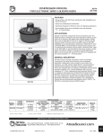
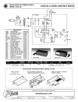
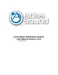
VT/VTF SERIES
TERMINAL STRIPS
INSTALLATION INSTRUCTIONS
VT SERIES UL-LISTING REQUIREMENTS
MODELS WITH 3, 4 OR 5 POSITION TERMINAL STRIP
SENSITIVITY 96dB (1W/1M)
FREQUENCY RESPONSE: 600-5500Hz
TERMINAL STRIP
NO. OF TERMINALS
VT/VTF MODELS WITH 3, 4 OR 5 POSITION TERMINAL STRIP P
3
VT/VTF-22U
VT/VTF-22UC
4
VT/VTF-17U
VT/VTF-17UC
5
VT/VTF-152U
VT/VTF-152UC
VT/VTF-27U
VT/VTF-27UC
VTB-5
VTB-6
VT/VTF-157U
VT/VTF-157UC
VTB-3
VTB-4
SPEAKER #1
SPEAKER #2
1
3
2
4
1
5
2
3
4
5
2
1
3
4
VT/VTF-17U
VT/VTF-17UC
VT/VTF-27U
VT/VTF-27UC
VTB-5
70V Line Xfmr
5
2
1
3
Outgoing Leads to
Next Speaker or EOL Resistor
Incoming Leads
Incoming Leads
User Selected Terminal
For Desired Wattage
User Selected Terminal
For Desired Wattage
User Selected Terminal
For Desired Wattage
User Selected Terminal
For Desired Wattage
Terminal #1
(Common)
Terminal #1
(Common)
Terminal #1
(Common)
Terminal #1
(Common)
Mounting Bracket
Mounting Bracket
Mounting Bracket
Mounting Bracket
VT/VTF-22U
VT/VTF-22UC
VTB-6
70V Line Xfmr
5
4
Outgoing Leads to
Next Speaker or EOL Resistor
VT/VTF-157U
VT/VTF-157UC 70
VTB-3
25V Line Xfmr
VT/VTF-152U
V VT/VTF-152UC
VTB-4
70V Line Xfmr
25V Line Xfmr
Term
Color
Watt
Term
Color
Watt
Term
Color
Watt
Term
Color
Watt
Term
Color
Watt
1
2
3
4
1
Red
Blu
Yel
Wht
Red
Com
1/4
1/2
1
Com
1
2
3
1
1
Red
Blu
Wht
Red
Red
Com
1
2
Com
Com
1
2
3
1
1
Red
Blu
Wht
Red
Red
Com
1
2
Com
Com
1
+2
+3
+4
+5
Wht
Red
Gry
Brn
Grn
Com
2
4
8
15
1
2
3
4
5
Wht
Red
Gry
Brn
Grn
Com
2
4
8
15
VT/VTF MODELS WITH 2 POSITION TERMINAL STRIP:
VT/VTF-154U, VT/VTF-158U, VTB-2, VTB-1
SPEAKER #1
SPEAKER #2
Mounting Bracket
Mounting Bracket
Terminal #1
(Common)
Terminal #1
(Common)
1
1
2
2
Incoming Leads
Outgoing Leads to
Next Speaker or EOL Resistor
MODELS WITH POSITION TERMINAL STRIP
NOTE: To conform with U.L. 464 and 1480 requirements, wires must be connected to appropriate terminals as shown in wiring diagram.
Do not use looped wire under terminals. Break wire run to provide for supervision of connection.
• Models with a "C" suffix include a supervisory capacitor for installation with supervised circuitry. Maximum supervised circuit voltage is 24 VDC.
• For use in ambient temperature ranges from -40˚C to 66˚C.
Installation must comply with all Building Codes and NFPA guidelines. Installation must adhere to
N.E.C. and NFPA 70/72 wiring directives and comply with all National and Local Building Codes.
Specifications are subject to change without notice
www.AtlasSound.com
1601 JACK MCKAY BOULEVARD ENNIS, TEXAS U.S.A. •
©2005 ATLAS SOUND LP
Printed in U.S.A.
00105
TELEPHONE: (800) 876-3332 • FAX: (800) 765-3435
ATS000746 RevC 01/05
PN 8805000