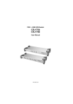
1
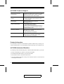
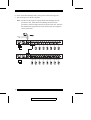
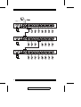
User Manual
KH88
2004-05-24
FCC Information
This is an FCC Class A product. In a domestic environment this product may cause
radio interference in which case the user may be required to take adequate measures.
This equipment has been tested and found to comply with the limits for a Class A
digital device, pursuant to Part 15 of the FCC
Rules. These limits are designed to provide reasonable protection against
harmful interference when the equipment is operated in a commercial
environment. This equipment generates, uses and can radiate radio frequency
energy and, if not installed and used in accordance with the instruction manual,
may cause harmful interference to radio communications. Operation of this
equipment in a residential area is likely to cause harmful interference in which
case the user will be required to correct the interference at his own expense.
© Copyright 2002-2004 ALTUSEN by ATEN® PAPE-0236-1AX
All brand names and trademarks are the registered property of their
2004-05-24
respective owners.
Package Contents
The complete KH88 package contains the following components:
w 1 KH88 KVM Switch
w 1 Power Cord
w 1 Rack Mounting Kit
w 1 User Manual
w 1 Quick Start Guide
w 1 Warranty Registration Card
Check to make sure that all the components are present and in good order. If
anything is missing, or was damaged in shipping, contact your dealer.
Read this manual thoroughly and follow the installation and operation
procedures carefully to prevent damage to the switch or any of the devices that
connect to it.
iii
2004-05-24
Contents
1. Introduction
Overview . . . . . . . .
Features . . . . . . . . .
Hardware Requirements
Console . . . . . . .
Computer . . . . . .
Cables . . . . . . . .
.
.
.
.
.
.
.
.
.
.
.
.
.
.
.
.
.
.
.
.
.
.
.
.
.
.
.
.
.
.
.
.
.
.
.
.
.
.
.
.
.
.
.
.
.
.
.
.
.
.
.
.
.
.
.
.
.
.
.
.
.
.
.
.
.
.
.
.
.
.
.
.
.
.
.
.
.
.
.
.
.
.
.
.
.
.
.
.
.
.
.
.
.
.
.
.
.
.
.
.
.
.
.
.
.
.
.
.
.
.
.
.
.
.
.
.
.
.
.
.
.
.
.
.
.
.
.
.
.
.
.
.
.
.
.
.
.
.
.
.
.
.
.
.
.
.
.
.
.
.
2. Hardware Setup
Front Panel . . . . . . . . . . .
Rear Panel . . . . . . . . . . .
Installation . . . . . . . . . . .
Before you Begin . . . . . .
Single Station Installation .
Two Stage Installation . . .
Three Stage Installation . .
Setup Considerations . . . . . .
Hot Plugging . . . . . . . .
Powering Off and Restarting
Port ID Numbering . . . . .
Port Selection . . . . . . . .
.
.
.
.
.
.
.
.
.
.
.
.
.
.
.
.
.
.
.
.
.
.
.
.
.
.
.
.
.
.
.
.
.
.
.
.
.
.
.
.
.
.
.
.
.
.
.
.
.
.
.
.
.
.
.
.
.
.
.
.
.
.
.
.
.
.
.
.
.
.
.
.
.
.
.
.
.
.
.
.
.
.
.
.
.
.
.
.
.
.
.
.
.
.
.
.
.
.
.
.
.
.
.
.
.
.
.
.
.
.
.
.
.
.
.
.
.
.
.
.
.
.
.
.
.
.
.
.
.
.
.
.
.
.
.
.
.
.
.
.
.
.
.
.
.
.
.
.
.
.
.
.
.
.
.
.
.
.
.
.
.
.
.
.
.
.
.
.
.
.
.
.
.
.
.
.
.
.
.
.
.
.
.
.
.
.
.
.
.
.
.
.
.
.
.
.
.
.
.
.
.
.
.
.
.
.
.
.
.
.
.
.
.
.
.
.
.
.
.
.
.
.
.
.
.
.
.
.
.
.
.
.
.
.
.
.
.
.
.
.
.5
.7
.8
.8
.8
.9
11
13
13
14
15
16
3. OSD Operation
OSD Overview . . . . . . .
OSD Main Screen Headings
OSD Navigation . . . . . .
OSD Functions . . . . . . .
F1 GOTO . . . . . . . .
F2 LIST . . . . . . . . .
F3 SET . . . . . . . . .
F4 ADM . . . . . . . .
F7 SCAN . . . . . . . .
F8 LOUT . . . . . . . .
.
.
.
.
.
.
.
.
.
.
.
.
.
.
.
.
.
.
.
.
.
.
.
.
.
.
.
.
.
.
.
.
.
.
.
.
.
.
.
.
.
.
.
.
.
.
.
.
.
.
.
.
.
.
.
.
.
.
.
.
.
.
.
.
.
.
.
.
.
.
.
.
.
.
.
.
.
.
.
.
.
.
.
.
.
.
.
.
.
.
.
.
.
.
.
.
.
.
.
.
.
.
.
.
.
.
.
.
.
.
.
.
.
.
.
.
.
.
.
.
.
.
.
.
.
.
.
.
.
.
.
.
.
.
.
.
.
.
.
.
.
.
.
.
.
.
.
.
.
.
.
.
.
.
.
.
.
.
.
.
.
.
.
.
.
.
.
.
.
.
.
.
.
.
.
.
.
.
.
.
.
.
.
.
.
.
.
.
.
.
.
.
.
.
.
.
.
.
.
.
17
19
19
20
20
21
22
24
27
28
.
.
.
.
.
.
.
.
.
.
.
.
.
.
.
.
.
.
.
.
iv
2004-05-24
1
2
3
3
3
4
4. Hotkey Operation
Hotkey Port Control . . . .
Invoking Hotkey Mode .
Selecting the Active Port
Auto Scanning . . . . .
Skip Mode . . . . . . .
Hotkey Beeper Control . . .
Hotkey Summary Table . .
.
.
.
.
.
.
.
.
.
.
.
.
.
.
.
.
.
.
.
.
.
.
.
.
.
.
.
.
.
.
.
.
.
.
.
.
.
.
.
.
.
.
.
.
.
.
.
.
.
.
.
.
.
.
.
.
.
.
.
.
.
.
.
.
.
.
.
.
.
.
.
.
.
.
.
.
.
.
.
.
.
.
.
.
.
.
.
.
.
.
.
.
.
.
.
.
.
.
.
.
.
.
.
.
.
.
.
.
.
.
.
.
.
.
.
.
.
.
.
.
.
.
.
.
.
.
.
.
.
.
.
.
.
.
.
.
.
.
.
.
.
.
.
.
.
.
.
.
.
.
.
.
.
.
29
29
30
31
33
34
34
5. The Firmware Upgrade Utility
Introduction . . . . . . . . . . .
Purpose . . . . . . . . . . .
Before You Begin . . . . .
Performing the Upgrade . . . .
Starting the Upgrade . . . .
Upgrade Succeeded . . . . .
Upgrade Failed . . . . . . .
Firmware Upgrade Recovery
.
.
.
.
.
.
.
.
.
.
.
.
.
.
.
.
.
.
.
.
.
.
.
.
.
.
.
.
.
.
.
.
.
.
.
.
.
.
.
.
.
.
.
.
.
.
.
.
.
.
.
.
.
.
.
.
.
.
.
.
.
.
.
.
.
.
.
.
.
.
.
.
.
.
.
.
.
.
.
.
.
.
.
.
.
.
.
.
.
.
.
.
.
.
.
.
.
.
.
.
.
.
.
.
.
.
.
.
.
.
.
.
.
.
.
.
.
.
.
.
.
.
.
.
.
.
.
.
.
.
.
.
.
.
.
.
.
.
.
.
.
.
.
.
.
.
.
.
.
.
.
.
.
.
.
.
.
.
.
.
35
35
36
37
37
40
41
42
Appendix
Computer Connection Table .
Specifications . . . . . . . . .
OSD Factory Default Settings
Troubleshooting . . . . . . .
Clear Login Information . . .
Rack Mounting . . . . . . . .
Limited Warranty . . . . . . .
.
.
.
.
.
.
.
.
.
.
.
.
.
.
.
.
.
.
.
.
.
.
.
.
.
.
.
.
.
.
.
.
.
.
.
.
.
.
.
.
.
.
.
.
.
.
.
.
.
.
.
.
.
.
.
.
.
.
.
.
.
.
.
.
.
.
.
.
.
.
.
.
.
.
.
.
.
.
.
.
.
.
.
.
.
.
.
.
.
.
.
.
.
.
.
.
.
.
.
.
.
.
.
.
.
.
.
.
.
.
.
.
.
.
.
.
.
.
.
.
.
.
.
.
.
.
.
.
.
.
.
.
.
.
.
.
.
.
.
.
43
44
45
46
47
48
50
.
.
.
.
.
.
.
v
2004-05-24
About This Manual
This User Manual is provided to help you get the most from your KH88
system. It covers all aspects of installation, configuration and operation. An
overview of the information found in the manual is provided below.
Overview
Chapter 1, Introduction, introduces you to the KH88 System. Its purpose,
features and benefits are described.
Chapter 2, Hardware Setup presents the front and back panel components,
and explains
how to set up your installation — from a basic single stage hookup to a
complete three stage operation.
Chapter 3, OSD Operation, provides a complete description of the KH88’s
OSD (On Screen Display), and how to work with it.
Chapter 4, Hotkey Operation, details all of the concepts and procedures
involved in the
Hotkey operation of your KH88 installation.
Chapter 5, The Firmware Upgrade Utility, explains how to use this utility
to upgrade to the KH88’s firmware with the latest available versions.
Appendixes at the end of the manual provide technical and other important
information regarding the KH88.
vi
2004-05-24
Conventions
This manual uses the following conventions:
Courier
Indicates text that you should key in.
[]
Indicates keys you should press. For example, [Enter] means to
press the Enter key. If keys need to be chorded, they appear
together in the same bracket with a plus sign between them:
[Ctrl+Alt].
1.
Numbered lists represent procedures with sequential steps.
w
Bullet lists provide information
>
Indicates selecting an option on a menu. For example, Start >
Run means to open the Start menu, and then select Run.
Indicates critical information.
Getting Help
For additional help, advice, and information, ALTUSEN provides several
support options. If you need to contact ALTUSEN technical support with a
problem, please have the following information ready beforehand:
w Product model number, serial number, and date of purchase.
w Your computer configuration, including operating system, revision level,
expansion cards, and software.
w Any error messages displayed at the time the error occurred.
w The sequence of operations that led up to the error.
w Any other information you feel may be of help.
vii
2004-05-24
ALTUSEN Technical Support
North America Technical
Phone Support
Registered ALTUSEN product owners are entitled to
telephone technical support. Call the ALTUSEN
Technical Support Center: 949-453-8885.
International Technical Phone
Support
1. Contact your local dealer.
2. Call the ALTUSEN Technical Support Center:
1-949-453-8885.
Email Support
Email your questions and concerns to:
[email protected]
Online Troubleshooting
The ALTUSEN support website:
http://www.altusen.com/support
provides online troubleshooting that describes the
most commonly encountered problems and offers
possible solutions to them.
Online Documentation
User Manuals are available electronically at the
ALTUSEN support website:
http://www.altusen.com/support
Software Updates
Download the latest drivers and firmware for your
product from the ALTUSEN support website:
http://www.altusen.com/support
Product Information
For information about all of ALTUSEN’s products and how they can help you
connect without limits, visit ALTUSEN on the web at http://www.altusen.com
ALTUSEN Authorized Resellers
ALTUSEN provides the following ways to find an authorized reseller in your area:
w In the United States of America, call: 866-ALTUSEN
w In Canada and South America, call: 949-453-8885
w In all other locations, call: 886-2-8692-6789
w Visit ALTUSEN on the web at http://www.altusen.com for a list of locations
and telephone numbers
viii
2004-05-24
Chapter 1.
Introduction
Overview
The KH88 KVM Switch is a control unit that allows access to multiple
computers from a single console (keyboard, monitor, and mouse). Before the
development of KVM switching, the only way to control multiple computer
configurations from a single console was through a complex and costly
network. Now, with the KH88, you can easily access multiple computers in a
cost effective manner.
A single KH88 can control up to 8 computers. Since units can be cascaded to
three levels, in a full three stage installation up to 73 KH88s can control up to
512 computers - all from a single console.
Setup is fast and easy; plugging cables into their appropriate ports is all that is
entailed. There is no software to configure, so there is no need to get involved
in complex installation routines or be concerned with incompatibility problems.
Since the KH88 intercepts keyboard input directly, it works on any hardware
platform and with all operating systems.
There are three convenient methods to access any computer connected to the
installation: (1) using the push button port selection switches located on each
unit’s front panel; (2) entering Hotkey combinations from the keyboard; and (3)
selecting from menus provided by the On Screen Display (OSD). A powerful
Auto Scan feature also permits automatic scanning and monitoring of the
activities of all computers running on the installation one by one.
There is no better way to save time and money than with a KH88 installation.
By allowing a single console to manage all the attached computers, a KH88
installation: (1) eliminates the expense of having to purchase a separate
keyboard, monitor, and mouse for each computer; (2) saves all the space those
extra components would take up; (3) saves on energy costs; and (4) eliminates
the inconvenience and wasted effort involved in constantly moving from one
computer to another.
1
2004-05-24
Features
M Controls 8 computers from a single console
M Cascadable to three levels from any port - control up to 512 computers from
a single console
M Administrator/User password authorization for enhanced security protection
(PSP)
M Intelligent OSD (On Screen Display) and hotkey switching for efficient
system handling
M No software required - computer selection via front panel switches, hotkeys,
or On Screen Display (OSD)
M Auto Scan feature for monitoring user-selected computers
M Hot pluggable - add or remove computers without powering off the switch
M PS/2 mouse emulation for system bootup
M Console’s PS/2 mouse controls all connected computers
M PS/2 compatible mouse support - Microsoft Intellimouse Explorer and
Logitech FirstMouse+ support*
M Superior video quality: up to 2048 x 1536; DDC; DDC2; DDC2B
M Supports LCD suspend mode
M Low power warning
M Detachable front panel module for convenient rack mounting and
management
M Rack mountable in 19" (1U) system rack
M Patented ASIC Design for Enhanced Functionality and Compatibility
* 1. PS/2 compatible mouse support is for three button (wheel) mice.
2. The Logitech Mouse Ware program’s Change Device procedure does
not work on Microsoft NT systems.
2
2004-05-24
Hardware Requirements
Console
M A VGA, SVGA, or Multisync monitor capable of the highest resolution that
you will be using on any computer in the installation.
M A PS/2 style mouse
M A PS/2 style keyboard
Computer
The following equipment must be installed on each computer:
M A VGA, SVGA or Multisync card.
M A 6-pin mini-DIN (PS/2 style) mouse port.
M A 6-pin mini-DIN (PS/2 Style) keyboard port with +5V DC on pin 4 and
Ground on pin 3, or a 5-pin DIN (AT Style) keyboard port with +5V DC on
pin 5 and ground on pin 4.*
* See the note under Cables in the next section.
3
2004-05-24
Cables
Use of substandard cables may damage the connected devices or degrade
overall performance. For optimum signal integrity and to simplify the layout,
we strongly recommend that you use the following high quality CS Custom
Cable sets:
Cable Purpose
Connect to Computer
Cascading
Part Number
2L-1001P/C (1.8m) or
2L-1003P/C (3m)
Note: 1. The KH88 does not support serial mice. You cannot use
Serial-to-PS/2 adapters with the cables. Attempts to do so will not
work.
2. If your computer uses an AT style keyboard socket you will need to
purchase a PS/2-to-AT keyboard adapter (Part No. 2A-106, or any
standard keyboard adapter), in order to plug the cable into the
computer’s keyboard port.
4
2004-05-24
Chapter 2.
Hardware Setup
Front Panel
1
2
3
4
1. Port LEDs
The upper Port LEDs are the On Line LEDs; the lower ones are the Selected
Port LEDs:
w The On Line LEDs light GREEN to indicate that the computer attached
to the corresponding port is up and running. If the LED is flashing, it
indicates that the Port is being used for cascading to another KH88
switch (see Two Stage Installation, p. 9).
w The Selected LEDs light ORANGE to indicate that the computer
attached to the corresponding port is the one that has the KVM focus.
The LED is steady under normal conditions, but flashes when its port is
accessed under Auto Scan Mode (see F7 SCAN, p. 27).
2. Port Selection Switches
Press a switch to access the computer attached to the corresponding port.
w Pressing Buttons 1 and 2 simultaneously for 3 seconds performs a
Keyboard and Mouse Reset.
w Pressing 7 and 8 simultaneously starts Auto Scan Mode (see p. 27).
5
2004-05-24
3. Reset
w Use a thin object (such as the end of a paper clip, or a ballpoint pen), to
press this recessed switch in to initiate a warm reset.
w If the switch is kept in for longer than three seconds, a cold reset takes
place.
4. Power LED
w Lights steadily to indicate that the unit is receiving power.
w Flashes to indicate a low power condition.
6
2004-05-24
Rear Panel
1
2
3
4
5
1. Power Socket
2. Power Switch
3. Console Port Section
w If this is a first station unit, your monitor, keyboard and mouse plug in
here.
w If this is a daisy chained unit, the cables that link back to a port on a
higher KH88unit plug in here.
4. CPU Port Section
The cables that link to the computers plug in here.
5. Firmware Upgrade Section
w Firmware Upgrade Switch
During normal operation this switch should be in the NORMAL position.
w Firmware Upgrade Port
The Firmware Upgrade Cable that transfers the firmware upgrade data
from the administrator’s computer to the KH88 plugs into this RJ-11
connector.
w See p. 35 for firmware upgrading details.
7
2004-05-24
Installation
Before you Begin
1. Make sure that power to all the devices you will be connecting up
have been turned off. You must unplug the power cords of any
computers that have the Keyboard Power On function.
2. To prevent damage to your installation, make sure that all devices
on the installation are properly grounded.
Single Station Installation
In a Single Stage installation, there are no additional KH88’s cascaded down
from the first unit. To set up a single stage installation refer to the diagram
below (the numbers in the diagram correspond with the numbers of the
instruction steps), and do the following:
1. Plug your keyboard, mouse, and monitor into the unit’s Console Ports.
2. Use KVM cable sets (as described in the Cables section on p. 4), to connect
any available KH88 CPU Port to the Keyboard, Video and Mouse ports of
the computer you are installing.
3. Plug the power cord that came with this package into the KH88’s Power
Socket, and then into an AC power source.
4. Power on the KH88.
5. Turn on the power to the computers.
1
3
2
8
2004-05-24
Two Stage Installation
To control even more computers, up to eight additional KH88 units can be
cascaded from the CPU ports of the First Stage unit. The cascaded KH88s that
connect back to the First Stage unit are considered Second Stage units.
As many as 64 computers can be controlled in a complete two stage
installation. A table showing the relation between the number of computers and
the number of KH88 units needed to control them is provided on p. 43.
Note: 1. Mixing different KVM switch models on the same installation can
cause problems with OSD port switching. We strongly recommend
that all cascaded units be the same model as the First Stage unit.
2. If you are adding this switch into an already existing KH88
configuration, be sure to make it the First Stage unit. Otherwise, you
won’t get the benefit of its improved OSD features and functions.
To set up a two stage installation, do the following:
1. Make sure that power to all the devices you will be connecting up, including
all preexisting devices on the installation, have been turned off.
2. Use a KVM cable set (described in the Cables section, p. 4), to connect any
available CPU Port on the First Stage unit to the Console Port connectors of
the Second Stage unit.
3. Use KVM cable sets (described in the Cables section, p. 4), to connect any
available CPU port on the Second Stage unit to the Keyboard, Video, and
Mouse ports of the computers you are installing.
4. Plug the power cord that came with this package into the KH88’s Power
Socket, and then into an AC power source.
5. Repeat these steps for any other Second Stage units you wish to connect.
9
2004-05-24
6. Power on the Second Stage unit(s), then power on the First Stage unit.
7. Turn on the power to all the computers.
Note: The Power On sequence requires that all Second Stage units be
powered on first. After all the Second Stage units have been
powered on, the First Stage unit must be powered on next. After the
Second and First stage units have been powered on, the computers
can be powered on.
10
2004-05-24
Three Stage Installation
The procedures for setting up a three stage installation are essentially the same as
for a two stage installation. With a three stage setup, as many as 512 computers can
be controlled in a complete installation. A table showing the relation between the
number of computers and the number of KH88 units needed to control them is
provided on p. 43.
Note: 1. See Notes 1 and 2 at the beginning of the Two Stage Installation section.
2. KH88 units cannot be cascaded beyond the third level.
To set up a three stage installation, do the following:
1. Make sure that power to all the devices you will be connecting up, including
all preexisting devices on the installation, have been turned off.
2. Use a KVM cable set (described in the Cables section, p. 4), to connect any
available CPU Port on the Second Stage unit to the Console Port connectors
of the Third Stage unit.
3. Use KVM cable sets (described in the Cables section, p. 4), to connect any
available CPU port on the Third Stage unit to the Keyboard, Video, and
Mouse ports of the computers you are installing, as shown in the diagram on
page 12.
4. Plug the power cord that came with this package into the KH88’s Power
Socket, and then into an AC power source.
5. Repeat these steps for any other Third Stage units you wish to connect.
6. Power on the Third Stage unit(s); next, power on the Second Stage units;
finally, power on the First Stage unit.
7. Turn on the power to all the computers.
Note: The Power On sequence requires that all Third Stage units be powered
on first. After they are all on, the Second Stage units must be powered
on next. After all the Second Stage units are on, the First Stage unit
must be powered on. Only after all the KH88s have been powered on
following this sequence, can the computers be powered on.
11
2004-05-24
12
2004-05-24
Setup Considerations
Hot Plugging
The KH88 supports hot plugging. Components can be removed and added back
into the installation by unplugging and replugging their cables from their
respective ports without the need to shut the switch down. For hot plugging to
work properly, the following procedures must be observed:
Hot Plugging CPU Ports:
When hot plugging cables from the CPU ports:
1. The cable must be plugged back into the same port it was removed from.
2. The mouse cable must be plugged in before the keyboard cable.
3. After plugging the cable back in, you must perform a KVM Reset on the
First Stage unit (by pressing the Reset switch In).
Hot Plugging Console Ports:
The unit supports hot plugging of the keyboard, monitor, and mouse. When hot
plugging the mouse from the KH88’s console mouse port:
1. You may unplug the mouse and plug it back in again (to reset the mouse, for
example), as long as you use the same mouse.
2. If you plug in a different mouse, all the stations and all the computers on the
installation must be shut down for 10 seconds, then restarted. (Refer back to
the note describing the Power On sequence on p. 11, if necessary.)
Note: If, after hot plugging (or at any other time), there is no response to
mouse and/or PS/2 keyboard input, simultaneously press and hold Port
Select buttons 1 and 2 on the First Stage unit for 3 seconds to perform a
PS/2 Keyboard and PS/2 Mouse reset.
13
2004-05-24
Powering Off and Restarting
If it becomes necessary to Power Off one of the KH88 units, before starting it
back up you must do the following:
1. Shut down all the computers that are attached to the unit. If there are
stations cascaded down from it, all the cascaded stations and the computers
attached to them must be shut down, as well.
Note: 1. You must unplug the power cords of any computers that have the
Keyboard Power On function that are connected to the shut down
switches. Otherwise, the switches will still receive power from the
computers.
2. If the unit is operating under external power, unplug the power
adapter cable.
2. Wait 10 seconds, then plug the stations back in, starting with the lowest
stations in the chain and working back to the station you originally shut
down.
3. After all the KH88’s are up, power On the computers, starting with the ones
attached to the lowest stations in the chain and working back to the station
you originally shut down.
14
2004-05-24
Port ID Numbering
Each CPU Port on a KH88 installation is assigned a unique Port ID. You can
directly access any computer on any level of the installation by specifying the
Port ID of the CPU port that the computer is connected to - either with the
Hotkey port selection method, or with the OSD.
The Port ID is a one, two, or three digit number. It is determined by the Stage Level
and CPU Port number of the KH88 unit that a computer is connected to.
The first digit represents the CPU Port number of the First Stage unit; the
second digit represents the CPU Port number of the Second Stage unit; the third
digit represents the CPU Port number of the Third Stage unit.
w A computer attached to a First Stage unit has a one digit Port ID (from 1 - 8),
that corresponds to the CPU Port number that the computer is connected to.
w A computer attached to a Second Stage unit has a two digit Port ID.
The first digit represents the CPU Port number on the First Stage unit that the
Second Stage unit links back to; the second digit represents the CPU Port
number on the Second Stage unit that the computer is connected to.
For example, a Port ID of 2 3 refers to a computer that is connected to CPU Port 3
of a Second Stage unit that links back to CPU Port 2 of the First Stage unit.
w Likewise, a computer attached to a Third Stage unit has a three digit Port ID.
A Port ID of 2 4 1 refers to a computer that is connected to CPU Port 1 of a
Third Stage unit, that links back to CPU Port 4 of a Second Stage unit,
which, in turn, links back to CPU Port 2 of the First Stage unit.
15
2004-05-24
Port Selection
The KH88 provides three methods to obtain instant access to any computer on
your installation: Manual, OSD, and Hotkey.
Manual:
Simply press the appropriate Port Selection Switch on the unit’s front panel.
After you press the switch, the Selected LED lights to indicate that the port has
the KVM focus. The OSD (see p. 17) automatically switches to highlight the
computer that you have selected.
Note: 1. On a cascaded installation, you must press the Port Selection switch
on the KH88 Station that connects directly to the computer you want
to access.
2. Simultaneously pressing Port Selection buttons 7 and 8 on the First
Stage unit initiates the Auto Scan feature (see F7 SCAN, p. 27), in
which all the ports currently selected for Quick View scanning (see
Set Quick View Ports, p. 26), are cycled through. The length of time
spent on each port is determined with the Scan Duration setting under
the OSD’s F3 SET function (see p. 23).
OSD:
OSD (On Screen Display), provides a menu driven interface to handle the computer switching procedure to provide instant access to any computer on the installation. OSD operation is discussed in detail beginning on p. 17.
Hotkey:
Hotkeys allow you to conveniently provide KVM focus to a particular
computer from the keyboard, instead of having to manually select them by
pressing Port Selection switches. Hotkey operation is discussed in detail
beginning on p. 29.
16
2004-05-24
Chapter 3.
OSD Operation
OSD Overview
The On Screen Display (OSD) provides a visual, menu-driven, mouse enabled,
interface that offers quick and convenient computer access and control, as well
as efficient system administration including user management (access rights,
passwords, etc.).
Each OSD menu option activates a function that configures and controls the
operation of the KVM installation. All procedures start from the OSD Main
Screen. To bring up the OSD Main Screen, tap the Scroll Lock key twice. The
login dialog box appears:
Note: 1. [Scroll Lock] is the default OSD hotkey. You can optionally change
the Hotkey to the Ctrl key (see OSD Hotkey, p. 22, for details).
2. The screenshots in this chapter are for example purposes. The screens
that you see may vary slightly as to their wording and appearance.
Key in a valid username and password, then press [Enter].
Note: If this is the first time that the OSD is being run, or if the password
function has not been set, simply press [Enter]. The OSD Main Screen
comes up in Administrator Mode. In this mode, you have access to all
Administrator and User functions, and can set up operations (including
password authorization for the future), as you would like.
17
2004-05-24
After you log in, a screen similar to the one below appears:
F1:GOTO
F3:SET
F2:LIST
F4:ADM
ADMINISTRATOR
LIST:ALL
PN
QV
1 - 6- 6
1-6-7
1-6-8
1-7
1-8
2-1
2-2
2-3
F7:SCAN
F8:LOUT
NAME
ATEN INTL. 1
ATEN INTL. 2
ATEN INTL. 3
FAX SERVER 1
FAX SERVER 2
WEB SERVER 1
WEB SERVER 2
MAIL SERVER 1
Note: 1. The diagram depicts the Administrator’s Main Screen. The User Main
Screen does not show the F4 function, since it is reserved for the
Administrator and can’t be accessed by ordinary Users.
2. The OSD always starts in List view, with the highlight bar at the same
position it was in the last time it was closed.
3. Only the ports that have been set accessible by the Administrator for
the currently logged in User are visible (see SET ACCESSIBLE
PORTS, p. 26, for details).
18
2004-05-24
OSD Main Screen Headings
Heading
Explanation
PN
This column lists the Port ID numbers (see Port ID Numbering, p. 15), for
all the CPU ports on the installation. The simplest method to access a
particular computer is move the Highlight Bar to it, then press [Enter].
QV
If a port has selected for Quick View scanning (see Set Quick View
Ports, p. 26), an arrowhead symbol displays in this column to indicate so.
The computers that are powered on and are On Line have a Sun symbol
in this column to indicate so.
NAME
If a port has been given a name (see Edit Port Names, p. 25), its name
appears in this column.
OSD Navigation
Use the following procedures to navigate through OSD menus:
w To move up or down through the list one line at a time, Click the Up and
Down Triangle symbols (▲▼) or use the Up and Down Arrow Keys. If there
are more list entries than there is room for on the Main Screen, the screen
will scroll.
w To move up or down through the list one screen at a time, Click the Up and
Down Arrow symbols (éê), or use the [Pg Up] and [Pg Dn] keys. If there
are more list entries than there is room for on the Main Screen, the screen
will scroll.
w To activate a port, Double Click it, or move the Highlight Bar to it then
press [Enter].
w After executing any action, you automatically go back to the menu one level
above.
w To dismiss the current menu, and return to the previous one, press [Esc].
w To dismiss the Main Screen, and deactivate the OSD (but not log out), press
[Esc].
w To Logout, Click F8 at the top of the Main Screen, or press [F8].
19
2004-05-24
OSD Functions
OSD functions configure and control the OSD. Examples of what can be
accomplished with the OSD include: rapidly switching to any port; auto
scanning specifically selected ports; limiting the list of ports you wish to view;
designating a port as a Quick View Port; managing port names; user
management, system administration, and making OSD setting adjustments.
To access an OSD function:
1. Either Click a Function Key field at the top of the Main Screen, or press a
Function Key on the keyboard.
2. In the Submenus that appear make your choice either by Double Clicking it,
or moving the Highlight Bar to it, then pressing [Enter].
3. Press [Esc] to return to the previous menu level.
A complete description of the KH88’s OSD operations are given in the sections
that follow.
F1 GOTO:
GOTO allows you to switch directly to a port either by keying in the port’s
Name, or its Port ID.
w To use the Name method, key in 1; key in the port’s Name; then press
[Enter].
w To use the Port ID method, key in 2; key in the Port ID; then press [Enter].
Note: You can key in a partial Name or Port ID. In that case, the screen will
show all the computers that the User has View rights to (see SET
ACCESSIBLE PORTS, p. 26), that match the Name or Port ID pattern,
regardless of the current List settings (see F2 LIST, p. 21, for details).
To return to the OSD Main Screen without making a choice, press [Esc].
20
2004-05-24
F2 LIST:
Many of the OSD functions only operate on the computers that have been
selected for Listing (displaying) on the Main Screen. This function lets you
broaden or narrow the scope of which ports are selected for Listing. The
submenu choices and their meanings are given in the table below:
Choice
Meaning
ALL
Lists all of the ports on the installation.
QUICK VIEW*
Lists only the ports that have been selected as Quick View Ports
(see p. 26).
POWERED ON
Lists only the ports that have their attached computers Powered
On.
QUICK VIEW +
POWERED ON*
Lists only the ports that have been selected as Quick View Ports
(see p. 26), and that have their attached computers Powered On.
* Only the Administrator has the rights to designates which ports are Quick
View ports (see p. 26, for details).
To select ports for the LIST:
1. Move the Highlight Bar to the choice you want, then press [Enter]. An icon
appears before the choice to indicate that it is the currently selected one.
2. After you make your choice and press [Enter], you return to the OSD Main
Screen with the newly formulated List displayed.
21
2004-05-24
F3 SET:
This function allows each operator to set up his own working environment. A
separate profile for each is stored by the OSD and is activated according to the
Username that was provided during Login.
To change a setting:
1. Double Click it; or move the highlight bar to it, then press [Enter].
2. After you select an item, a submenu with further choices appears. To make a
selection, either Double Click it; or move the Highlight Bar to it, then press
[Enter]. An icon appears before the selected choice to indicate which one it
is.
Note: All your setting changes are stored in temporary memory and remain in
effect for the duration of your session. The changes only become
permanent when you Log out of the OSD (see p. 28). If you shut down
the KH88 without first logging out, your changes are discarded.
The settings are explained in the following table:
Setting
OSD HOTKEY
Function
Selects which Hotkey activates the OSD function:
[Scroll Lock] [Scroll Lock] or [Ctrl] [Ctrl].
Since the Ctrl key combination may conflict with programs running
on the computers, the default is the Scroll Lock combination.
PORT ID
DISPLAY
POSITION
Allows you to position where the Port ID appears on the monitor.
The default is the upper left corner, but you can have it appear
anywhere on the screen.
Use the Mouse or the Arrow Keys plus Pg Up, Pg Dn, Home, End,
and 5 (on the numeric keypad with Num Lock off), to position the
Port ID display, then Double Click or press [Enter] to lock the
position and return to the Set submenu.
(Table continues on next page)
22
2004-05-24
(F3 SET: continued)
Setting
Function
PORT ID
DISPLAY
DURATION
Determines how long a Port ID displays on the monitor after a port
change has taken place. The choices are: User Defined - which
lets you select the amount of time (from 1 - 255 sec.); and Always
On - which displays the Port ID at all times. If you select User
Defined, key in the number of seconds, then press [Enter]. The
default is 3 Seconds. A setting of 0 (zero) disables this function.
PORT ID
DISPLAY
MODE
Selects how the Port ID is displayed: the Port Number alone (PORT
NUMBER); the Port Name alone (PORT NAME); or the Port
Number plus the Port Name (PORT NUMBER + PORT NAME).
The default is PORT NUMBER + PORT NAME).
SCAN
DURATION
Determines how long the focus dwells on each port as it cycles
through the selected ports in Auto Scan Mode (see F7 SCAN, p.
27). Key in a value from 1 - 255 seconds, then press [Enter].
Default is 5 seconds; a setting of 0 disables the Scan function.
SCAN/SKIP
MODE
Selects which computers will be accessed under Auto Scan Mode
(see F7 SCAN, p. 27). Choices are:
ALL - All the Ports which have been set Accessible (see SET
ACCESSIBLE PORTS, p. 26);
POWERED ON - Only those Ports which have been set Accessible
and are Powered On;
QUICK VIEW - Only those Ports which have been set Accessible
and have been selected as Quick View Ports (see SET QUICK
VIEW PORTS, p. 26);
QUICK VIEW + POWERED ON - Only those Ports which have
been set Accessible and have been selected as Quick View Ports
and are Powered On.
The default is ALL.
Note: The Quick View choices only show up on an Administrator’s
screen, since only he has Quick View setting rights (see SET
QUICK VIEW PORTS, p. 26, for details).
SCREEN
BLANKER
If there is no input from the console for the amount of time set with
this function, the screen is blanked. Key in a value from 1 - 30
minutes, then press [Enter]. A setting of 0 disables this function.
The default is 0 (disabled).
HOTKEY
COMMAND
MODE
Enables / Disables the Hotkey function (see p. 29) in case a conflict
with programs running on the computers occurs. The default is
enabled.
23
2004-05-24
F4 ADM:
F4 is an Administrator only function. It allows the Administrator to configure
and control the overall operation of the OSD. To change a setting use the Up
and Down Arrow Keys to move the highlight bar to it then press [Enter].
After you select an item, a submenu with further choices appears. Double Click
the choice you want, or move the Highlight Bar to it then press [Enter]. An
icon appears before the selected choice to indicate which one it is. The settings
are explained in the following table:
Note: All your setting changes are stored in temporary memory and remain in
effect for the duration of your session. The changes only become
permanent when you Log out of the OSD (see p. 28). If you shut down
the KH88 without first logging out, your changes are discarded.
Setting
SET
USERNAME
AND
PASSWORD
Function
This function is used to set Usernames and Passwords:
1. Usernames and Passwords for one Administrator and four
Users can be set.
2. After you select one of the User fields or the Administrator field,
a screen that allows you to key in a Username and Password
appears. The password may be up to 15 characters long, and
can consist of any combination of letters and numbers
(A - Z, 0 - 9).
3. For each individual, key in the Username and Password, then
press [Enter].
4. To modify or delete a previous Username and/or Password,
use the backspace key to erase individual letters or numbers.
Note: To clear all Username and Password information and have
the Switch return to its default (empty) state, see Clear Login
Information, p. 47.
SET LOGOUT
TIMEOUT
If there is no input from the console for the amount of time set with
this function, the Operator is automatically logged out. A login is
necessary before the console can be used again.
This enables other Operators to gain access to the computers when
the original Operator is no longer accessing them, but has forgotten
to log out. To set the timeout value, key in a number from 1 - 180
minutes, then press [Enter]. If the number is 0 [zero], this function
is disabled. The default is 0 (disabled).
(Table continues on next page)
24
2004-05-24
(F4 ADM: continued)
Setting
EDIT PORT
NAMES
Function
To help remember which computer is attached to a particular port,
every port can be given a name. This function allows the
Administrator to create, modify, or delete port names. To Edit a port
name:
Note: Only the Ports currently chosen for the LIST view on the main
OSD screen (see F2 LIST, p. 21), show up here.
1. Click the port you want, or use the Navigation Keys to move
the highlight bar to it, then press [Enter].
2. Key in the new Port Name, or modify/delete the old one. The
maximum number of characters allowed for the Port Name is
15. Legal characters include:
w All alpha characters: a - z; A - Z
w All numeric characters: 0 - 9
w + - / : . and Space
Case does not matter; the OSD displays the Port Name in all
capitals no matter how they were keyed in.
3. When you have finished editing, press [Enter] to have the
change take effect. To abort the change, press [Esc].
RESTORE
DEFAULT
VALUES
This function is used to undo all changes and return the setup to the
original factory default settings (see FACTORY DEFAULT
SETTINGS, p. 45) - except for the Names settings that were
assigned to the Ports, which are saved.
CLEAR THE
NAME LIST
This function is similar to Restore Default Values. The difference is
that it also clears the Names settings along with undoing all
changes and returning the setup to the original factory default
settings.
ACTIVATE
BEEPER
Choices are Y (for Yes), or N (for No). When activated, the beeper
sounds whenever a Port is changed; when activating the Auto Scan
function (see F7 SCAN, p. 27); or an invalid entry is made on an
OSD menu. The default is Y (activated).
(Table continues on next page)
25
2004-05-24
(F4 ADM: continued)
Setting
SET QUICK
VIEW PORTS
Function
This function lets the Administrator select which Ports to include as
Quick View ports.
Note: Only the Ports currently chosen for the LIST view on the main
OSD screen (see p. 21), show up here.
w To select/deselect a port as a Quick View Port, Double Click the
port you want, or use the Navigation Keys to move the highlight
bar to it, then press [Enter].
w When a port has been selected as a Quick View Port, an
arrowhead displays in the QV column of the LIST on the Main
Screen to indicate so. When a port is deselected, the
arrowhead disappears.
w If one of the Quick View options is chosen for the LIST view
(see F2 LIST, p. 21), only a Port that has been selected here
will display on the List.
w If one of the Quick View options is chosen for Auto Scanning
(see SCAN/SKIP MODE, p. 23), only a Port that has been
selected here will be Auto Scanned.
The default is for no ports to be selected.
SET
ACCESSIBLE
PORTS
This function allows the Administrator to define Operator access to
the computers on the installation on a Port-by-Port basis.
For each Operator, select the target Port; then press the [Spacebar]
to cycle through the choices: F (Full access), V (View Only), or
blank (No access). Repeat until all access rights have been set,
then press [Enter]. The default is F for all users on all Ports.
Note: A blank setting means that no access rights are granted. The
Port will not show up on the User’s LIST on the Main Screen.
FIRMWARE
UPGRADE
In order to upgrade the KH88’s firmware (see Chapter 5), you must
first invoke Firmware Upgrade Mode with this setting. Only the
Super Administrator on the Master Station can utilize this function.
SET PS/2 CLK
DELAY MODE
Use this setting to adjust the PS/2 clock timing. Press the
[Spacebar] to cycle through the choices (0, 1, 2). The default is 0
(zero).
Note: You should only change this setting from the default of 0 if
you encounter keyboard or mouse input problems due to a PS/2
clock delay problem.
26
2004-05-24
F7 SCAN:
This function allows you to automatically switch among the available
computers at regular intervals so that you can monitor their activity without
having to take the trouble of switching yourself.
w The selection of computers to be included for Auto Scanning is made with
the Scan/Skip Mode setting under the F3 SET function (see p. 23).
w The amount of time that each Port displays for is set with the Scan Duration
setting under the F3 SET function (see p. 23). When you want to stop at a
particular location, press the [Spacebar] or [Esc] to stop scanning and exit
Auto Scan Mode.
w If the scanning stops on an empty port, or one where the computer is
attached but is powered Off, the monitor screen will be blank, and the mouse
and keyboard will have no effect. Simply wait - after the Scan Duration time
is up, the Scan function will move on to the next port.
w As each computer is accessed, an S appears in front of the Port ID display to
indicate that it is being accessed under Auto Scan Mode.
w While Auto Scan Mode is in effect, the console will not function normally.
You must exit Auto Scan Mode in order to regain control of the console.
w While you are in Auto Scan Mode, you can pause the scanning in order to
keep the focus on a particular computer either by pressing P, or with a Left
Click of the mouse. See Starting Auto Scan, p. 32, for details.
w To exit Auto Scan Mode, press the [Spacebar] or [Esc].
27
2004-05-24
F8 LOUT:
LOUT (Log Out) logs you out of OSD control of the computers, and blanks the
Console screen. This is different from simply pressing [Esc] to deactivate the
OSD when you are at the Main Screen. With this function you must log in all
over again to regain access to the OSD, whereas with [Esc], all you have to do
to reenter the OSD is tap the OSD Hotkey.
Note: 1. When you reenter the OSD after logging out, the screen stays blank
except for the OSD Main Screen. You must input your password
before you can continue.
2. If you reenter the OSD after logging out, and immediately use [Esc]
to deactivate the OSD without having selected a port from the OSD
menu, a Null Port message displays on the screen. The OSD Hotkey
will bring up the Main OSD Screen.
28
2004-05-24
Chapter 4.
Hotkey Operation
Hotkey Port Control
Hotkey Port Control allows you to provide KVM focus to a particular computer
directly from the keyboard. The KH88 provides the following features:
w Selecting the Active Port
w Auto Scanning
w Skip Mode Switching
Invoking Hotkey Mode
All Hotkey operations begin by invoking Hotkey Mode. Invoking Hotkey Mode
is a three step procedure:
1. Press and hold down the Num Lock key
2. Tap the asterisk key or the minus key
3. Release the Num Lock key:
[Num Lock] + [*];
Or:
[Num Lock] + [-];
When HKM is active:
w A Command Line appears on the monitor screen. The command line prompt
is the word Hotkey: in yellow text on a blue background. Hotkey
information that you key in displays on the command line.
w Ordinary keyboard and mouse functions are suspended - only Hotkey
compliant keystrokes and mouse clicks (described in the sections that
follow), can be input.
w Pressing [Esc] or [Spacebar] exits HKM.
29
2004-05-24
Selecting the Active Port
Each CPU port is assigned a Port ID (see Port ID Numbering, p. 15). You can
directly access any computer on the installation with a Hotkey combination that
specifies the Port ID of the CPU Port that the computer is connected to. The
steps involved are:
1. Invoke HKM (see p. 29)
2. Key in the Port ID
The Port ID numbers display on the Command Line as you key them in. If
you make a mistake, use [Backspace] to erase the wrong number.
3. Press [Enter]
After you press [Enter], the KVM focus switches to the designated computer
and you automatically exit HKM.
Port Key In Examples:
w To access a computer attached to Port 3 of a Single Stage installation, key in
3 for the Port ID, as follows:
[Numlock] + [*] 3 [Enter]
w To access a computer attached to Port 3 of a Second Stage unit that is
cascaded down from Port 2 of the First Stage unit, key in 23 for the Port ID,
as follows:
[Numlock] + [*] 2 3 [Enter]
Note: You must key in the numbers one at a time.
w To access a computer attached to Port 8 of a Third Stage unit that links back
to Port 4 of a Second Stage unit, which, in turn, links back to CPU Port 6 of
the First Stage unit key in 648 for the Port ID, as follows:
[Numlock] + [*] 6 4 8 [Enter]
30
2004-05-24
Auto Scanning
Auto Scan automatically switches among all the active CPU Ports that are
accessible to the currently logged on User at regular intervals (see Scan Mode
of the OSD F3 SET function, p. 23), so that he can monitor their activity
automatically.
Setting the Scan Interval:
The amount of time Auto Scan dwells on each port is set with the Scan
Duration setting of the OSD F3 SET function (see p. 23). You can change the
scan interval before activating Hotkey Auto Scanning, if you wish, with the
following Hotkey combination:
1. Invoke HKM (see p. 29)
2. Key in [T] [n]
Where [T] is the letter T, and [n] is a number from 1-255 that represents the
number of seconds for the dwell time.
The letter T, and the numbers display on the Command Line as you key
them in. If you make a mistake, use [Backspace] to erase the wrong number.
3. Press [Enter]
After you press [Enter], you automatically exit Hotkey Mode, and are ready
to start Auto Scanning.
31
2004-05-24
Starting Auto Scan:
To start Auto Scanning, key in the following Hotkey combination:
1. Invoke HKM (see p. 29)
2. Key in [A]
After you press A, you automatically exit Hotkey Mode, and enter Auto
Scan Mode.
3. To exit Auto Scan Mode, press [Esc] or [Spacebar]
Note: While Auto Scan Mode is in effect, ordinary keyboard and mouse
functions are suspended - only Auto Scan Mode compliant
keystrokes and mouse clicks can be input. You must exit Auto Scan
Mode in order to regain normal control of the console.
While you are in Auto Scan Mode, you can pause the scanning in order to
keep the focus on a particular computer by pressing P. During the time that
Auto Scanning is paused, the Command Line displays: Auto Scan:
Paused.
Pausing when you want to keep the focus on a particular computer is more
convenient than Exiting Auto Scan Mode because when you Resume
scanning, you start from where you left off. If, on the other hand, you Exited
and restarted, Scanning would start over from the very first computer on
the installation.
After pausing, to resume Auto Scanning, press any key. Scanning continues from where it left off.
32
2004-05-24
Skip Mode
This feature allows you to switch between computers in order to monitor them
manually. You can dwell on a particular port for as long or as little as you like as opposed to Auto Scanning, which automatically switches after a fixed
interval. To invoke Skip Mode, key in the following Hotkey combination:
1. Invoke HKM (see p. 29)
2. Key in [Arrow]
Where [Arrow] refers to the left or right Arrow key. After you press
[Arrow], you automatically exit HKM, and enter Previous/Next Mode where
you can switch ports as follows:
← Skips from the current port to the first accessible port previous to it.
(See Scan Mode, p. 23, for information regarding accessible ports.)
→ Skips from the current port to the next accessible port.
3. To exit Skip Mode, press [Esc] or [Spacebar]
Note: While Skip Mode is in effect, ordinary keyboard and mouse functions
are suspended - only Skip Mode compliant keystrokes can be input. You
must exit Skip Mode in order to regain normal control of the console.
33
2004-05-24
Hotkey Beeper Control
The Beeper (see Activate Beeper, p. 25) can be Hotkey toggled On and Off. To
toggle the Beeper, key in the following Hotkey combination:
1. Invoke HKM (see p. 29)
2. Key in [B]
After you press [B], the Beeper toggles On or Off. The Command Line
displays Beeper On or Beeper Off for one second; then the message
disappears and you automatically exit Hotkey Mode.
Hotkey Summary Table
[Num Lock] + [*] or
[Num Lock] + [-]
[Port ID] [Enter]
Switches access to the computer that
corresponds to that Port ID.
[T] [n] [Enter]
Sets the Auto Scan interval to n seconds
- where n is a number from 1 - 255.
[A]
Invokes Auto Scan Mode.
When Auto Scan Mode is in effect, [P] or
Left Click pauses Auto Scanning.
When Auto Scanning is paused, pressing
Any Key or another Left Click resumes
Auto Scanning.
[←]
Invokes Skip Mode and Skips from the
current port to the first accessible port
previous to it.
[→]
Invokes Skip Mode and Skips from the
current port to the next accessible port.
[B]
Toggles the Beeper On or Off.
[R] [Enter]
Resets the KVM settings back to their
defaults.
34
2004-05-24
Chapter 5.
The Firmware Upgrade Utility
Introduction
Purpose
The purpose of the Windows-based Firmware Upgrade Utility
(FWUpgrade.exe) is to provide an automated process for make upgrading the
KVM switch’s firmware as smooth and painless as possible.
The program comes as part of a Firmware Upgrade Package that is specific for
each device.
As new firmware revisions become available, new firmware upgrade packages
are posted on our web site:
http://www.altusen.com
Check the web site regularly to find the latest information and packages.
Note: The screenshots in the descriptions below are for example purposes. The
screens that appear during your firmware upgrade may vary somewhat
as to their wording and appearance.
35
2004-05-24
Before You Begin
To prepare for the firmware upgrade, do the following:
1. From a computer that is not part of your KVM installation go to our Internet
support site and choose the model name that relates to your device (KH88)
to get a list of available Firmware Upgrade Packages.
2. Choose the Firmware Upgrade Package you want to install (usually the most
recent), and download it to your computer.
3. Use the Firmware Upgrade Cable provided with this unit, to connect a
COM port on your computer to the Firmware Upgrade Port of your switch.
4. Shut down the computers on your KH88 installation.
5. From your KVM switch console, bring up the OSD (see p. 17) and select the
F4 ADM function.
6. Scroll down to FIRMWARE UPGRADE (see p. 26). Press [Enter], then
press [Y] to invoke Firmware Upgrade Mode. For your reference, the
current firmware upgrade version displays on the screen.
36
2004-05-24
Performing the Upgrade
Starting the Upgrade
To upgrade your firmware:
1. Run the downloaded Firmware Upgrade Package file - either by double
clicking the file icon, or by opening a command line and keying in the full
path to it.
The Firmware Upgrade Utility Welcome screen appears:
2. Read and Agree to the License Agreement (enable the I Agree radio button).
37
2004-05-24
3. Click Next to continue. The Firmware Upgrade Utility main screen appears:
The Utility inspects your installation. The devices capable of being upgraded
by the package are listed in the Device List panel.
4. As you select a device in the list, its description appears in the Device
Description panel.
38
2004-05-24
5. After you have made your device selection(s), Click Next to perform the
upgrade.
If you enabled Check Firmware Version, the Utility compares the device’s
firmware level with that of the upgrade files. If it finds that the device’s
version is higher than the upgrade version, it brings up a dialog box
informing you of the situation and gives you the option to Continue or
Cancel.
If you didn’t enable Check Firmware Version, the Utility installs the
upgrade files without checking whether they are a higher level, or not.
As the Upgrade proceeds status messages appear in the Status Messages
panel, and the progress toward completion is shown on the Progress bar.
39
2004-05-24
Upgrade Succeeded
After the upgrade has completed, a screen appears to inform you that the
procedure was successful:
Click Finish to close the Firmware Upgrade Utility.
40
2004-05-24
Upgrade Failed
If the upgrade failed to complete successfully a dialog box appears asking if
you want to retry. Click Yes to retry. If you Click No, the Upgrade Failed
screen appears:
Click Cancel to close the Firmware Upgrade Utility. See the next section,
Firmware Upgrade Recovery, for how to proceed.
41
2004-05-24
Firmware Upgrade Recovery
There are basically two conditions that call for firmware upgrade recovery:
w When you begin a firmware upgrade, but decide not to proceed with it.
w When the Mainboard firmware upgrade fails.
Note: If one of the cascaded switches fails to upgrade successfully, unplug it
from the installation and perform the recovery and upgrade operation
independently. After it has been successfully upgraded, plug it back into
the installation.
To perform a firmware upgrade recovery, do the following:
1. Power off the switch.
2. Slide the Firmware Upgrade Recovery Switch (see p. 7) to the Recover
position.
3. Use the Firmware Upgrade Cable (provided with this unit), to connect a
COM port on your computer with the Firmware Upgrade Port of the switch.
4. Power the switch back on.
5. Follow the upgrade procedures that begin with the Starting the Upgrade
section (p. 37).
6. After the upgrade completes successfully, power the switch off, once again.
7. Slide the Firmware Upgrade Recovery Switch back to the Normal position.
8. Power the switch back on.
This completes the Firmware Upgrade Recovery operation, and your switch is
ready for use.
42
2004-05-24
Appendix
Computer Connection Table
The following table indicates the relationship between the number of KH88
Units and the number of computers that they control:
Units
Computers
Units
Computers
Units
Computers
Units
Computers
1
8
20
134 - 141
39
267 - 274
58
400 - 407
2
8-15
21
141 - 148
40
274 - 281
59
407 - 414
3
15 - 22
22
148 - 155
41
281 - 288
60
414 - 421
4
22 - 29
23
155 - 162
42
288 - 295
61
421 - 428
5
29 - 36
24
162 - 169
43
295 - 302
62
428 - 435
6
36 - 43
25
169 - 176
44
302 - 309
63
435 - 442
7
43 - 50
26
176 - 183
45
309 - 316
64
442 - 449
8
50 - 57
27
183 - 190
46
316 - 323
65
449 - 456
9
57 - 64
28
190 - 197
47
323 - 330
66
456 - 463
10
64 - 71
29
197 - 204
48
330 - 337
67
463 - 470
11
71 - 78
30
204 - 211
49
337 - 344
68
470 - 477
12
78 - 85
31
211 - 218
50
344 - 351
69
477 - 484
13
85 - 92
32
218 - 225
51
351 - 358
70
484 - 491
14
92 - 99
33
225 - 232
52
358 - 365
71
491 - 498
15
99 - 106
34
232 - 239
53
365 - 372
72
498 - 505
16
106 - 113
35
239 - 246
54
372 - 379
73
505 - 512
17
113 - 120
36
246 - 253
55
379 - 386
18
120 - 127
37
253 - 260
56
386 - 393
19
127 - 134
38
260 - 267
57
393 - 400
43
2004-05-24
Specifications
Function
Computer
Connections
Direct
8
Max
512 (via Cascade)
Port Selection
LEDs
Connectors
Specification
Front Panel Switches
On Screen Display (OSD)
Hotkeys
Power
1 (Blue)
On Line Port
8 (Green)
Selected Port
8 (Orange)
Keyboard
1 x 6 pin mini-DIN female - Console
8 x 6 pin mini-DIN female - CPU Ports
Mouse
1 x 6 pin mini-DIN female - Console
8 x 6 pin mini-DIN female - CPU Ports
Video
1 x HDB-15 female - Console
8 x HDB-15 male - CPU Ports
Scan Interval (OSD Select)
1 - 255 secs. (def. 5 secs.)
Power Consumption
100 - 240V AC; 50 - 60 Hz
Operating Temperature
0 - 50o C
Storage Temperature
-20 - 60o C
Humidity
0 - 80% RH; Noncondensing
Housing
Metal
Weight
3.7 kg
Dimensions (L x W x H)
43.3 x 21.6 x 4.4 cm (1U)
44
2004-05-24
OSD Factory Default Settings
The factory default settings are as follows:
Setting
Default
OSD Hotkey
[Scroll Lock] [Scroll Lock]
Port ID Display Position
Upper Left Corner
Port ID Display Duration
3 Seconds
Port ID Display Mode
The Port Number plus the Port Name
Scan Duration
5 Seconds
Scan Mode
All
Screen Blanker
0 (Off)
Logout Timeout
0 (Off)
Beeper
Y (Activated)
Accessible Ports
F (Full) For all Users on all Ports
45
2004-05-24
Troubleshooting
Symptom
Possible Cause
Action
Pressing the
Hotkeys gets
no response.
The connection from
the selected port to the
target computer has
been broken, or the
computer is turned
OFF.
Check the Online LED for the selected port. If
it is not lit:
1. Manually press one of the Select switches to
connect to a computer that is powered ON.
2. Check the cables to make sure they are all
properly connected.
Improper keyboard
reset.
1. Reset the keyboard (and mouse) by
simultaneously pressing Buttons 1 and 2 on
the First Stage unit for 3 seconds.
2. Unplug the keyboard connector from the
Console Keyboard Port, then plug it back in.
Mouse is not
responding.
Improper KH88 reset.
Turn off all KH88 units and wait five seconds
before turning them back on. See Powering
Off and Restarting, p. 14, for details.
Incorrectly keying in
the Port ID.
After invoking the Hotkey function with the
[Numlock /] combination, be sure to key in the
Port ID and press [Enter] within one second
for each key.
Improper mouse
reset.
1. Reset the mouse (and keyboard) by
simultaneously pressing Buttons 1 and 2 on
the First Stage unit for 3 seconds.
2. Unplug the mouse connector from the
Console Mouse Port, then plug it back in.
PS/2 clock delay
problem.
In the OSD, set the PS/2 Clock Delay setting
to 1 or 2. See SET PS/2 CLK DELAY MODE,
p. 26, for details)
46
2004-05-24
Clear Login Information
If you are unable to perform an Administrator login (because the Username and
Password information has become corrupted, or you have forgotten it, for
example), you can clear the login information with the following procedure:
1. Power off the switch and open the case.
2. Short the jumper J22 (labeled Restore Default Password) at the center front
of the switch’s main board.
3. Power on the switch.
When you power the switch on, the following message appears:
USERNAME AND PASSWORD INFORMATION HAS BEEN CLEARED.
PLEASE POWER OFF THE SWITCH, REMOVE THE JUMPER, CLOSE
THE CASE, THEN RESTART.
After you start back up, the OSD login function acts exactly the way it did the
first time the switch was run.
47
2004-05-24
Rack Mounting
To rack mount the unit do the following:
1. Separate the front and rear modules by removing the four module attaching
screws:
2. Screw the rack mounting brackets into the front and rear modules:
48
2004-05-24
3. Screw the mounting brackets to the rack.
49
2004-05-24
Limited Warranty
IN NO EVENT SHALL THE DIRECT VENDOR’S LIABILITY EXCEED
THE PRICE PAID FOR THE PRODUCT FROM THE DIRECT, INDIRECT,
SPECIAL, INCIDENTAL OR CONSEQUENTIAL DAMAGES RESULTING
FROM THE USE OF THE PRODUCT, DISK OR ITS DOCUMENTATION.
The direct vendor makes no warranty or representation, expressed, implied, or
statutory with respect to the contents or use of this documentation, and
specially disclaims its quality, performance, merchantability, or fitness for any
particular purpose.
The direct vendor also reserves the right to revise or update the device or
documentation without obligation to notify any individual or entity of such
revisions, or update. For further inquires please contact your direct vendor.
50
2004-05-24
Index
A
H
Activate Beeper . . . . . . . . . . . . . . . 25
ADM . . . . . . . . . . . . . . . . . . . . . . . . 24
Auto Scanning . . . . . . . . . . . . . 27, 31
Scan Duration. . . . . . . . . . . . . . . 23
Setting the Scan Interval . . . . . . 31
Hardware setup. . . . . . . . . . . . . . . . . 5
Hot plugging. . . . . . . . . . . . . . . . . . 13
Hotkey
Beeper control . . . . . . . . . . . . . . 34
Command Mode . . . . . . . . . . . . 23
Exit hotkey mode . . . . . . . . . . . . 29
Invoking Hotkey Mode . . . . . . . 29
OSD . . . . . . . . . . . . . . . . . . . . . . 22
Port Control . . . . . . . . . . . . . . . . 29
Selecting the active port . . . . . . 30
Summary table . . . . . . . . . . . . . . 34
B
Beeper
Activate . . . . . . . . . . . . . . . . . . . 25
Hotkey control . . . . . . . . . . . . . . 34
C
Clear the Name List . . . . . . . . . . . . 25
Computer Connection Table . . . . . 43
E
Edit Port Names . . . . . . . . . . . . . . . 25
Exit hotkey mode . . . . . . . . . . . . . . 29
I
Installation
Single stage . . . . . . . . . . . . . . . . . 8
Three stage . . . . . . . . . . . . . . . . . 11
Two stage . . . . . . . . . . . . . . . . . . . 9
Invoking Hotkey Mode . . . . . . . . . 29
L
F
F1 GOTO . . . . . . . . . . . . . . . . . . . . 20
F2 LIST. . . . . . . . . . . . . . . . . . . . . . 21
F3 SET . . . . . . . . . . . . . . . . . . . . . . 22
F4 ADM . . . . . . . . . . . . . . . . . . . . . 24
F7 SCAN . . . . . . . . . . . . . . . . . . . . 27
F8 LOUT . . . . . . . . . . . . . . . . . . . . 28
Firmware upgrade
utility . . . . . . . . . . . . . . . . . . . . . 35
Front panel . . . . . . . . . . . . . . . . . . . . 5
G
GOTO . . . . . . . . . . . . . . . . . . . . . . . 20
2004-05-24
LIST . . . . . . . . . . . . . . . . . . . . . . . .
Logout. . . . . . . . . . . . . . . . . . . . . . .
Logout Timeout . . . . . . . . . . . . . . .
LOUT . . . . . . . . . . . . . . . . . . . . . . .
21
28
24
28
O
OSD
Functions . . . . . . . . . . . . . . . . . .
Hotkey . . . . . . . . . . . . . . . . . . . .
Logout . . . . . . . . . . . . . . . . . . . .
Main Screen . . . . . . . . . . . . . . . .
Main Screen Headings. . . . . . . .
Navigation . . . . . . . . . . . . . . . . .
Overview . . . . . . . . . . . . . . . . . .
20
22
28
18
19
19
17
P
S
Password. . . . . . . . . . . . . . . . . . . . .
Pause. . . . . . . . . . . . . . . . . . . . . . . .
Port ID
Display Duration . . . . . . . . . . . .
Display Mode . . . . . . . . . . . . . .
Display Position. . . . . . . . . . . . .
Port ID numbering . . . . . . . . . . . . .
Port Names . . . . . . . . . . . . . . . . . . .
Port selection . . . . . . . . . . . . . . . . .
Powering off and restarting . . . . . .
24
27
23
23
22
15
25
16
14
Q
Quick View Ports . . . . . . . . . . . . . . 26
SCAN . . . . . . . . . . . . . . . . . . . . . . . 27
Scan Duration. . . . . . . . . . . . . . . . . 23
SCAN/SKIPMODE . . . . . . . . . . . . 23
Screen Blanker . . . . . . . . . . . . . . . . 23
Selecting the active port. . . . . . . . . 30
SET. . . . . . . . . . . . . . . . . . . . . . . . . 22
Accessible Ports. . . . . . . . . . . . . 26
Logout Timeout . . . . . . . . . . . . . 24
Password . . . . . . . . . . . . . . . . . . 24
Quick View Ports . . . . . . . . . . . 26
USERNAME . . . . . . . . . . . . . . . 24
Setting the Auto Scan Interval . . . . 31
Skip Mode . . . . . . . . . . . . . . . . 23, 33
T-U
R
Rear panel. . . . . . . . . . . . . . . . . . . . . 7
Restore Default Values . . . . . . . . . 25
Timeout . . . . . . . . . . . . . . . . . . . . . 24
Username . . . . . . . . . . . . . . . . . . . . 24
2004-05-24