1
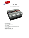
ATD-5956
3000 WATT INVERTER
Welcome.
This ATD p roduct has been carefu lly enginee red and manufactured to g ive
you dependable operation. Please read this manual thoroughly before operating your new ATD
product, as it contains the information you need to become familiar with its features and obtain
the performance that will bring you continued enjoyment for many years. Please keep this
manual on file for future reference.
About ATD Inverters.
ATD, an innovator in portable inverter design, has developed a new line of super-efficient power
inverters with the highest surge capability in the industry. These extremely advanced,
microprocessor controlled units run cooler and more reliable than any in their class. Their
superior surge capability allows them to start even the most difficult loads, including color
televisions, TV/VCR combinations, microwaves, refrigeration units, and even small air
conditioners! They also have the highest efficiency available (up to 90%), which translates into
longer running time and extended battery life.
Inverters convert low voltage, direct current (DC) to 110-volt alternating current (AC).
Depending on the model and its rated capacity, the inverters draw power either from standard
12 volt automobile and marine batteries or from portable high power 12 volt sources.
Getting Started
When you turn on an appliance or a tool that operates using a motor or tubes, it requires an
initial surge of power to start up. This surge of power is referred to as the "starting load" or "peak
load". Once started, the tool or appliance requires less power to continue to operate. This is
referred to as "continuous load" in terms of power requirements. You will need to determine how
much power your tool or appliance requires to start up (starting load) and it's continued running
power requirements (continuous load). Power consumption is rated either in wattage (watts), or
in amperes (amps), and this information is usually stamped or printed on most appliances and
equipment. If this information is not indicated on the appliance or equipment, check the owner's
manual or contact the manufacturer to determine if the device you are using is compatible with
a modified sine wave source.
1
Multiply: AMPS X 110 (AC voltage) = WATTS
This formula yields a close approximation of the continuous load of your appliance
Multiply: WATTS X 2 = Starting Load
This formula yields a close approximation of the starting load of your appliance. Most often the
start up load of the appliance or power tool determines whether your inverter has the capability
to power it.
To determine whether the inverter will operate a particular piece of equipment or appliance, run
a test. The inverters are designed to automatically shut down in the event of a power overload.
This protection feature prevents damage to the unit while testing appliances and equipment
with ratings in the 3000 watt range.
If an appliance in the 3000 watt range will not operate properly when first connected to the
inverter, turn the inverter rocker switch ON(I), OFF(0), and ON(I) again in quick succession. If
this procedure is not successful, it is likely that the inverter does not have the required capacity
to operate the appliance in question.
Important
z
z
z
The inverter is designed to operate from a 12-volt power source only. Do not attempt to
connect the inverter to any other power source, including any AC power source.
Do not attempt to extend or otherwise modify the 12-volt power cord attached to your
inverter.
110 volts of current can be lethal. Improper use of your inverter may result in property
damage, personal injury or loss of life.
2
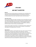
A.
B.
C.
D.
E.
F.
G.
H.
J.
K.
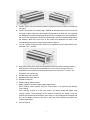
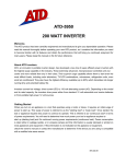
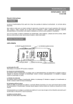
ON/OFF Switch. The current flowing from the power source to the inverter is controlled by
this switch.
ON/OFF and protect LED Indicator Light. GREEN will illuminate when turn the inverter ON
at normal condition. When the internal operating temperature exceeds 165 °F. this light will
turn RED and the inverter will automatically shut down. Immediately turn off the appliance if
this occurs The High Speed Cooling Fan automatically activates excessive temperatures
are detected. When this occurs turn off the inverter and determine the cause of the
overload before turning the inverter and the appliance back on.
110v AC Outlets, recommend each outlet use an appliance not more than 3000W. Each
outlet with 110V, 1.5A Max.
High-Speed cooling fans. When the temperature inside the inverter exceeds the limits of
safe operation the Cooling Fan automatically turns on to cool the inverter. When the
temperature has lowered to a safe operating mode, the fan will shut off. The fan is not
designed to run continuously.
Positive Power Input Terminal.
Negative Power Input Terminal.
Remote Housing Set.
Display reading selection switch
Battery voltage and inverter output wattage digital meters.
WATT Reading: When selection switch at "watt" position. The digital number displays
"watt" reading.
VOLT Reading: If switch is on the "volt" position. The digital number will display input
"voltage" reading. These readings are the result of measuring the voltage in both the
positive and negative input terminals on the inverter. In a high voltage draw the display will
show a low voltage level due to the drop in volts that occurs between the positive and
negative input cables.
Ground Terminal
3
Selecting A Power Supply.
When you operate the inverter for long periods of time combined with a high continuous load
demand, the result will be a large power drain from the battery. With this in mind, check the
reserve capacity of the battery you plan to use to power your inverter.
To calculate the approximate power drain on your battery you will want to estimate the reserve
power ("amp/hour") of the battery and the amps the inverter will require, to meet the continuous
load demand of the appliance.
1. When calculating the amp/hour of the battery, find its “reserve minutes" rating. This is
typically is marked on the battery label along with the "Cold Cranking Amps" (CCA) rating.
If you multiply the reserve minutes rating of the battery by 0.3 it will tell
you the battery amp/hour.
2. To estimate the maximum battery power the inverter will require to run a piece of
equipment or appliance, divide its continuous load wattage equipment by 10.
3. Conclusion: The reserve power of a battery with a 150 reserve minutes rating is sufficient
to satisfy the continuous load demand placed on the inverter for a maximum of about one
hour. (45 amps/hour-amp draw = 1 hour).
Note:
z
z
z
z
The type of battery you use to power your inverter is important. Batteries designed to start
engines have multiple layers of very thin plates. These provide extensive surface area that
will produce a powerful short burst of electrical power required to start combustion engines.
Using an inverter will cause a battery to discharge and recharge often. We recommend that
you use a different type of battery that is designed specifically for this type of load
requirement.
Deep cycle (marine) batteries generally have the highest reserve ratings. They are
designed with thicker plates making them capable of withstanding repeated complete
drains of power and recharging. If you do not have a deep cycle battery we recommend
t h a t y o u r u n t h e e n g i n e o f y o u r v e h i c l e w h e n o p e r a t i n g t h e i n v e r t e r.
When the inverter will be operating appliances with high continuous load ratings for
extended periods, it is not advisable to power the inverter with the same batter used to
power your car or truck. If the car or truck battery is utilized for an extended period, it is
possible that the battery voltage may be drained to the point where the battery has
insufficient reserve power to start the vehicle.
It may be advisable to operate the inverter from a bank of batteries of the same type in a
"parallel" configuration. Two such batteries will generate twice the amp\hours of a single
battery; three batteries will generate three times the amp hours and so on.
Connection Cable Gauges.
When connecting the inverter to the power source use the thickest wire available, in the
shortest length practical. If the inverter and the battery are positioned within four feet of each
other, a minimum of # 0 gauge wire should be used to make the connections. See the last page
of this manual for recommendations.
4
Connecting Your inverter.
1.
2.
Make sure the ON/OFF switch located on the front panel of the inverter is in the OFF(0)
position.
Connect the cables to the power input terminals at the rear of the Inverter. Make sure to
match the negative (Black) terminal on the 12-volt power source first. Then repeat this
procedure with the positive (Red) terminal connecting a wire to the positive terminal of the
12V volt power source. Make sure you have good secure connections, but do not over
tighten these screws.
Note:
z
z
z
3.
4.
5.
6.
7.
8.
Loose connections can result in a severe decrease in voltage, which may cause damage to
the wires and insulation.
Failure to make a proper connection between the inverter and the power source will result
in reverse polarity. Reverse polarity will blow the internal fuses in the inverter and may
cause permanent damage to the inverter. Damage caused by reverse polarity is not
covered under the warranty.
Making the connection between the Positive terminals may cause a spark as a result of
current flowing to charge capacitors within the inverter. This is a normal occurrence. Due to
the possibility of sparking, however, it is extremely important that both the inverter and the
12-volt battery be positioned far from any possible source of flammable fumes or gases.
Failure to heed this warning could result in fire or explosion.
Locate the Ground Lug Terminal at the rear of the inverter. Run a wire from this terminal to
a proper grounding point using the shortest practical length 2 AWG wire, or as described on
the last page of this manual. You can connect this wire to the chassis of your vehicle or to
the grounding system in your boat. As an alternative when in remote locations the ground
wire can be connected to the earth (one way to accomplish this is to attach it to a metal rod
driven into the ground). Before connecting the ground, make certain that the inverter is
turned off.
Operating the inverter without correctly grounding the unit may result in electrical
shock.
Turn On (I) the inverter. Make certain that the Over Load LED Indicators are not lit.
Turn OFF (0) the inverter. The Over Load and LEDS may briefly "blink". This is normal. The
internal audible alarm may also sound a short "chirp" This is also normal.
When you have confirmed that the appliance to be operated is turned off, plug the
appliance into one of the four 110V AC Outlets on the front panel of the inverter.
Turn the inverter on.
Turn the appliance on.
Note:
z
z
The audible alarm may make a momentary "chirp" when the inverter is turned OFF(0). This
same alarm may also sound when the inverter is being connected to or disconnected from
the 12-volt power source.
When using an extension cord from the inverter to the appliance the extension cord should
be no more than 50 feet long. At this length there should be no measurable decrease in
power from the inverter.
5
Television and Audio Suggestions
Although these inverters are shielded and filtered to minimize signal interference, some
interference with your television picture may be unavoidable, especially with weak signals.
However, here are some suggestions that may improve reception.
1. First, make sure that television antenna produces a clear signal under normal operating
conditions. Also, ensure that the antenna cable is properly shielded and of good quality.
2. Change the positions of the inverter, antenna cables and television power cord.
3. Isolate the television, its power cord and antenna cables from the 12 volt power source by
running an extension cord from the inverter to the television set.
4.
Coil the television power cord and the input cables running from the 12 volt
power source to the inverter.
5.
Attach a "Ferrite Data Line Filter" to the television power cord. More than one filter may be
required. These filters are available at most electronic supply stores.
Note:
z
Inexpensive sound systems may emit a "buzzing" sound when operated with the inverter.
This is due to inadequate filters in the sound system. There is no solution to this problem
short of purchasing a sound system with a higher quality power supply.
Operating a Microwave oven with Your Power Inverter
The power rating used with microwave ovens is the "cooking power" which qualifies as the
power being "delivered" to the food being micro waved. The actual operating power
requirement rating is higher than the cooking power rating. This is usually referenced on
the back of the microwave. If the operating power requirement cannot be found on the back of
the microwave, check the owner's manual or contact the manufacturer.
Safety Precautions.
For best results place the power inverter on a reasonably flat surface.
z Keep the inverter dry. Do not expose it to rain or moisture.
DO NOT operate the inverter if the inverter, device being operated or any other surfaces
that may come in contact with any power source are wet. Water and many other liquids can
conduct electricity, which may lead to serious injury or death.
z Avoid placing the inverter on or near heating vents, radiators or other sources of heat. Do
not leave the inverter in the passenger compartment of your vehicle. Store in a cool dry
place. Do not place the inverter in direct sunlight. Ideal air temperature should be between
50°F and 80°F.
z In order to properly disperse heat generated while the inverter is in operation, keep it well
ventilated. While in use, maintain several inches of clearance around the top and sides of
the inverter.
z Do not use the inverter near flammable materials. Do not place the inverter in areas such
as battery compartments where fumes or gases may accumulate.
6
How Power Inverters Work.
There are two stages in which a power inverter changes the 12 volt DC (or
battery) power into 110V AC (household current).
STAGE 1:
The inverter uses a DC to DC converter to increase the DC input voltage from the power source
to 145 volts DC.
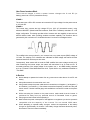
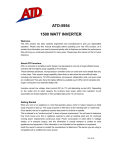
STAGE 2:
The inverter then converts the high voltage DC into 110V AC (household current), using
advanced MOSFET (Metal-Oxide-Semiconductor Field Effect Transistor) transistors in a full
bridge configuration. This design provides all our inverters with the capability to start and run
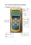
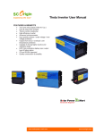
difficult reactive loads, while providing excellent overload capability The waveform that is
generated by this conversion is a "modified sine wave" as shown in the diagram below.
The modified sine wave produced by our inverters has a root mean square (RMS) voltage of
110 volts. The majority of AC voltmeters are calibrated for RMS voltage and assume that the
measured waveform will be a pure sine wave.
Consequently, these meters will not read the RMS modified sine wave voltage correctly and,
when measuring the inverter output, the meters will read about 20 to 30 volts too low. To
accurately measure of the output voltage of the inverter, use a true RMS reading voltmeter
such as a Fluke 87 Fluke 8060A Beckman 4410, Triplet 4200 or any multimeter identified as
"True RMS"
In Review.
z
z
z
z
z
z
z
Never attempt to operate the inverter from any power source other than a 12-volt DC volt
battery.
Always disconnect the inverter when not in use.
Always make certain the power cable terminal connections run Negative (-) to Negative (-)
and Positive (+) to Positive (+). Check these connections frequently to make sure they are
remain secure. Use the heaviest gauge wire available to connect the inverter to the power
source.
While connecting the inverter to the power source, make certain that the inverter is
positioned far away from any potential source of flammable fumes or gases,
Always ground the inverter before operating it.
Make certain the power consumption of the appliance or equipment you wish to operate is
compatible with the capacity of the inverter. Do not exceed 3000 watts.
When attempting to operate battery chargers, monitor the temperature of the battery
charger for approximately 10 minutes. If the battery charger becomes abnormally warm,
disconnect it from the inverter immediately.
7
z
z
z
z
z
z
z
When operating the inverter with an automobile or marine battery, start the engine every 30
to 60 minutes and let it run for approximately 20 minutes to recharge the battery.
In the event of a continuous audible alarm or automatic shut down, turn the inverter OFF
immediately. Do not restart the inverter until the source of the problem has been identified
and corrected.
To avoid battery drain, always disconnect the inverter when not in use.
Do not expose the inverter to rain or moisture.
Avoid placing the inverter near sources of heat or in direct sunlight.
While in use, make sure the inverter is properly ventilated.
Do not operate the inverter near flammable materials, fumes or gases.
8
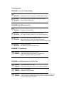
Troubleshooting
PROBLEM: Low or No Output Voltage
Reason: Poor contact with lighter socket or battery clamps
Solution: Unplug and reinsert 12 volt plug or reattach battery clamps.
Reason: Using incorrect type of voltmeter to test output voltage.
Solution: Use true RMS reading meter.
PROBLEM: Red LED Indicator On
Reason: Battery voltage below 9.5 volts.
Solution: Recharge or replace battery.
Reason: Equipment being operated draws too much power.
Solution: Use a higher capacity inverter or do not use this equipment.
Reason: Inverter is too hot (thermal shut down mode).
Solution: Allow inverter to cool. Check for adequate ventilation.
Reduce the load on the inverter to rated continuous power output.
Reason: Unit may be defective.
Solution: See Warranty and call customer service.
PROBLEM: TV Interference
Reason: Electrical interference from the inverter.
Solution: Add a ferrite data line filter on to the TV power cord.
Refer to TV & Audio section of this manual.
PROBLEM: Low Battery Alarm On All The Time
Reason: Input voltage below 10.5 volts.
Solution: Keep input voltage above 10.5 volts to maintain regulation.
Reason: Poor or weak battery.
Solution: Recharge or Replace battery.
Reason: Inadequate power being delivered to the inverter or excessive voltage drop
Solution: Check condition of cigarette lighter socket. Clean or replace if necessary.
Or check cable clamp connections.
9
PROBLEM: TV Does Not Work
Reason: TV does not turn on.
Solution: Try turning the inverter ON/OFF/ON. Contact TV manufacturer for start
up surge specifications and/or to see if the TV is compatible with a
modified sine wave. A larger inverter may be required.
SPECIFICATION:
Max. Continuous Powe r................... ......................................... 3000 Watts
Surge Capability (Peak Power) ................................................... 6000 Watts
No Load Current Draw .................................................................. <2A
Waveform ............................. .......................... ......... ...Modif ied S ine Wave
Input Voltage Range ................................................................. DC10-15V
AC Receptacles .............................................. 110V AC 3 prong grounded
Fuse ....................................................................... 12 x 30 amp (spade type)
Dimensions…………………………………………..501Lx230Wx155Hmm (19.72” x 9.06” x 6.10”)
Weight………..………………………………………………………….………...….…...…………24Ib
INVERTER CABLES
200W & 400W COME WITH A CIGARETTE LIGHTER PLUG/CABLE
& CLAMP ON BATTERY CABLES
800W OR GREATER MUST BE HARD WIRED TO BATTERY
*USE THE THICKEST WIRE AVAILABLE IN THE SHORTEST LENGTH PRACTICAL
Wattage
0'-4' Length
5'-10' Length
800W
#2 AWG
#0 AWG
1000W
#0 AWG
#2/0 AWG
1500W
#0 AWG
#2/0 AWG
2000W
#2/0 AWG
#4/0 AWG
3000W
#2/0 AWG
#4/0 AWG
6000W
#2/0 AWG
#4/0 AWG
10