1
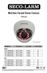
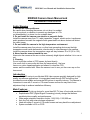
BWX560 Users Manual and Installation Instructions
BWX560 Camera Users Manual and
Installation Instructions
Safety Warning
1. Handle the camera with care.
Be careful when handling the camera, do not drop it or subject
it to strong shock or vibration to prevent any damages to it. Do
not disassemble it or place it on an unstable base.
2. Do not install the camera near electric or magnetic fields.
Install the camera away from TV, radio transmitter, magnet, electric motor, transformer,
audio speakers because the magnetic fields generated from above devices will distort
the video image.
3. Do not install the camera in the high temperature environment.
Install the camera away from stoves, or other heat generating devices as the high
temperature could cause deformation, discoloration or other damage to the camera.
Install the camera where the temperature range will stay between 0 to 50 (32 to 122).
4. Never face the camera toward the sun.
Never aim the camera at the sun or other extremely bright objects whether it is in use or
not.
5. Cleaning
Do not touch the surface of CCD sensor by hand directly.
Use a soft cloth to remove the dirt from the camera body. Use lens
tissue or a cotton tipped applicator and ethanol to clean the CCD
sensor and the camera lens. When the camera is not in use, put the cover cap on the
lens mount.
Introduction
The new BWX560 series is a solid-state B/W video camera specially designed for high
quality surveillance applications. It incorporates break-through DSP technology that
provides the most reliable and accurate B/W picture in security industry. The camera is
convenient to use with C-mount or CS-mount lenses and has an easy back-focus
adjustment help to achieve installation efficiency.
Main Features :
•
•
•
•
•
•
1/3” B/W CCD pick-up device for more than 560 TV lines of horizontal resolution
Sophisticated DSP (Digital Signal Processing) circuitry design that delivers
excellent picture quality and performance.
Wide range automatic electronic shutter: 1/60(1/50)~1/100,000 sec
Auto line lock with external phase adjustment
Used with either C-mount or CS-mount lenses and easy back-focus adjustment.
System available in EIA or CCIR.
1
BWX560 Users Manual and Installation Instructions
Specification
Pickup Device:
Picture Element:
Horizontal resolution:
Sensitivity:
S/N ratio:
Electronic shutter:
Auto. Iris:
Flickerless:
Back Light Comp:
Electronic Shutter:
Auto Gain Control:
Line Lock:
Audio:
Gamma Correction:
Video output:
Sync. Mode:
Lens Mount:
Power source:
Dimension:
Operating Temperature:
Power Consumption:
1/3 inch interline transfer B/W CCD
768x494 (EIA)752x582 (CCIR)
560 TV lines
0.01 lux/F=1.2
Over 48 dB
1/60(1/50)~1/100,000 sec
Video / Direct Drive switch
On/Off
On/Off
On/Off
On/Off
On/Off
Yes
> 0.45
1.0Vp-p,75 ohm(BNC)
1. Line-Locked with LL on
2. Internal Sync. With LL off
C/CS mount back focus adjustment
90-260VAC (EQ150)
12VDC/24VAC (EQ150A)
51x57x140.2mm
0_ to +50_
5W max
2
BWX560 Users Manual and Installation Instructions
Major Parts Names and Their Functions
1. Focal Length Adjustment Ring
Use this ring to adjust the appropriate focal length according to the type of lens. Rotate
the ring clockwise for the CS-mount lens, rotate it counterclockwise for the C-mount
lens. The factory setting is C-mount.
2. Lens Mount
To mount an appropriate C-mount or CS-mount lens.
3. Locking Screw
3
BWX560 Users Manual and Installation Instructions
Use the locking screw to fix the focal length.
4. Lens Connector (4 pin socket)
To connect to the lens plug of the auto iris lens.
5. Control Switches
There are 6 control switches located on the sideboard, which are for the setting
of the special features. The switches in orders are for Flickerless, Back Light
Compensation, Electronic Shutter, Automatic Gain Control, Line-Lock and Auto
Iris Lens type.
FL (Flickerless Function) On/Normal
When picture flicker fiercely, turn FL on, then the camera will stabilize the speed
of electronic shutter at 1/100(EIA) or 1/120(CCIR) automatically, and reduce the
flicker immediately. The default setting is Normal.
BLC (Back Light Compensation) On/Normal
When BLC is turned on, the AGC, ES and IRIS operating point is
determined by averaging over the center area instead of entire field-of-view, so
that a dimly-lit foreground object at center area can be clearly distinguished from
brightly-lit backgrounds.
BLC should not be used unless it is needed to compensate for back-lit. The
default setting is Normal.
ES (Electronic Shutter) Off/On
ES ON: The camera continuously adjusts the shutter speed from 1/60 (EIA),
1/50(CCIR) second to 1/100,000 second according to the luminance conditions
of the scene.
ES OFF: The shutter speed is fixed at 1/60 (EIA), 1/50 (CCIR) second.
Set ES OFF, when auto iris lens is used or flicker is observed under a very bright
fluorescent lamp. Otherwise, turn ES on for optimum performance. The default
setting is ON.
AGC (Automatic Gain Control) Off/On
AGC ON: The sensitivity increases automatically when light is low.
AGC OFF: A-low-noise picture is obtained under a low light condition The default
setting is ON.
LL (Line-Lock) Off/On
To select the sync mode between Internal Sync.(LL off) and Line-Lock (LL on).
Set the line-lock off, the camera will synchronize to the internal time base.
Set the line-lock on, the camera’s vertical synchronization can be driven bythe
AC signal in the power lines.
Note: Line-Lock sync mode operation is possible only when used with an AC
power source; it’s not possible with a DC power source.
VD/DD (Auto Iris lens Type)
For video drive auto iris lens, please set switch to VD. For direct drive iris lens,
set switch to DD. The default setting is DD. Wire the cable of lens to lens
connector according to the following table.
4
BWX560 Users Manual and Installation Instructions
6. IRIS Level Control
Brightness Level can be adjusted from the IRIS level VR while using the direct drive
lens.
• Turn counterclockwise to L to get darker picture.
• Turn clockwise to H to get brighter picture.
7. V-Phase Adjustment Screw
The vertical phase may require adjustment to synchronize the vertical phase of the
camera with other camera in the system when it is to be used in the line-lock sync
mode. Make the adjustment when the vertical phase of the camera does not match with
other cameras.
8. Mounting Base and Fixing Screws
To use when the mounting bracket is required while mounting the camera. The
mounting base can be attached to either the top or the bottom of the camera, fix the
mounting base onto the camera by using the 4 supplied fixing screws.
9. Video Output Connector
BNC VBS 1.0 Vp-p, 75ohm
10. Audio Out Connector
11. Power Cable
12. DC12V/AC24V Screw Terminals
5
BWX560 Users Manual and Installation Instructions
Installation Instructions
1. Remove the cover cap from the top of the lens mount.
2. To attach a C-mount/CS-mount lens, turn the focal length adjustment ring to the
appropriate position.
Note: If a C-mount lens is used, please make sure the focal length adjustment
ring is set at C position before fixing the lens.
3. Screw the lens firmly onto the lens mount. Insert the lens plug in the lens connector if
the auto iris lens is used.
4. Tighten the locking screw.
5. Connect the video output of the camera to a color monitor or other video device
through a 75 ohm type coaxial cable with BNC female connector.
6. Plug the power cord to the outlet.
7. Once the image appears on the monitor, adjust the focus and diaphragm of the lens
to obtain the best picture.
8. If the subject is not in focus when adjusting focus of lens, do focal length adjustment
as following:
i. Loosen the locking screw of the focal length adjustment ring.
ii. Take picture of subject at a distance more than 20m away from the camera.
iii. Rotate the focal length adjustment ring to bring the subject in focus.
iv. Tighten the locking screw while the adjustment is completed.
6