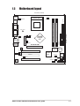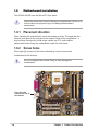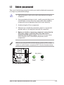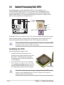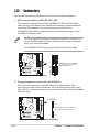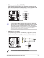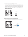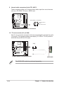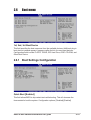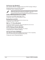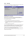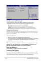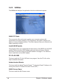
1
User Guide
Motherboard
A7N8X-VM/400
E1480
Checklist
First Edition V1
December 2003
Copyright © 2003 ASUSTeK COMPUTER INC. All Rights Reserved.
No part of this manual, including the products and software described in it, may be
reproduced, transmitted, transcribed, stored in a retrieval system, or translated into any
language in any form or by any means, except documentation kept by the purchaser for
backup purposes, without the express written permission of ASUSTeK COMPUTER INC.
(“ASUS”).
Product warranty or service will not be extended if: (1) the product is repaired, modified or
altered, unless such repair, modification of alteration is authorized in writing by ASUS; or (2)
the serial number of the product is defaced or missing.
ASUS PROVIDES THIS MANUAL “AS IS” WITHOUT WARRANTY OF ANY KIND, EITHER
EXPRESS OR IMPLIED, INCLUDING BUT NOT LIMITED TO THE IMPLIED WARRANTIES
OR CONDITIONS OF MERCHANTABILITY OR FITNESS FOR A PARTICULAR PURPOSE.
IN NO EVENT SHALL ASUS, ITS DIRECTORS, OFFICERS, EMPLOYEES OR AGENTS BE
LIABLE FOR ANY INDIRECT, SPECIAL, INCIDENTAL, OR CONSEQUENTIAL DAMAGES
(INCLUDING DAMAGES FOR LOSS OF PROFITS, LOSS OF BUSINESS, LOSS OF USE
OR DATA, INTERRUPTION OF BUSINESS AND THE LIKE), EVEN IF ASUS HAS BEEN
ADVISED OF THE POSSIBILITY OF SUCH DAMAGES ARISING FROM ANY DEFECT OR
ERROR IN THIS MANUAL OR PRODUCT.
SPECIFICATIONS AND INFORMATION CONTAINED IN THIS MANUAL ARE FURNISHED
FOR INFORMATIONAL USE ONLY, AND ARE SUBJECT TO CHANGE AT ANY TIME
WITHOUT NOTICE, AND SHOULD NOT BE CONSTRUED AS A COMMITMENT BY ASUS.
ASUS ASSUMES NO RESPONSIBILITY OR LIABILITY FOR ANY ERRORS OR
INACCURACIES THAT MAY APPEAR IN THIS MANUAL, INCLUDING THE PRODUCTS
AND SOFTWARE DESCRIBED IN IT.
Products and corporate names appearing in this manual may or may not be registered
trademarks or copyrights of their respective companies, and are used only for identification or
explanation and to the owners’ benefit, without intent to infringe.
ii
Contents
Features
Notices ........................................................................................................ v
Safety information ...................................................................................... vi
About this guide ......................................................................................... vii
A7N8X-VM/400 specification summary .................................................... viii
Chapter 1: Product introduction
1.1
Welcome! ....................................................................................... 1-2
1.2
Package contents .......................................................................... 1-2
1.3
Special features ............................................................................. 1-2
1.4
Motherboard components .............................................................. 1-4
1.5
Motherboard layout ........................................................................ 1-7
1.6
Motherboard installation ................................................................ 1-8
1.7
1.6.1 Placement direction ......................................................... 1-8
1.6.2 Screw holes ..................................................................... 1-8
Before you proceed ....................................................................... 1-9
1.8
Central Processing Unit (CPU) .................................................... 1-10
1.9
System memory ........................................................................... 1-11
1.10 Expansion slots ........................................................................... 1-12
1.10.1 Configuring an expansion card ...................................... 1-12
1.10.2 Standard Interrupt Assignments .................................... 1-12
1.10.3 AGP slot ......................................................................... 1-13
1.10.4 PCI slots ........................................................................ 1-13
1.11 Jumpers ....................................................................................... 1-14
1.12 Connectors .................................................................................. 1-16
Chapter 2: BIOS information
2.1
Managing and updating your BIOS ............................................... 2-2
2.2
2.1.1 Creating a bootable floppy disk ....................................... 2-2
2.1.2 Using AFUDOS to copy the current BIOS ....................... 2-3
2.1.3 Using AFUDOS to update the BIOS ................................ 2-4
2.1.4 Using ASUS EZ Flash to update the BIOS ...................... 2-5
2.1.5 ASUS Update .................................................................. 2-6
BIOS Setup program ..................................................................... 2-8
2.2.1
2.2.2
BIOS menu bar ................................................................ 2-8
Legend bar ....................................................................... 2-9
iii
Contents
2.3
Main menu ................................................................................... 2-10
2.4
2.3.1 Primary and Secondary IDE Master/Slave .................... 2-11
2.3.2 System Information ........................................................ 2-12
Advanced menu ........................................................................... 2-13
2.5
2.4.1 Chipset ........................................................................... 2-13
2.4.2 Onboard Devices Configuration ..................................... 2-14
2.4.3 PCIPnP .......................................................................... 2-16
Power menu ................................................................................ 2-18
2.6
2.5.1 Power Up Control .......................................................... 2-18
2.5.2 Hardware Monitor .......................................................... 2-20
Boot menu ................................................................................... 2-21
2.7
2.6.1 Boot Settings Configuration ........................................... 2-21
2.6.2 Security .......................................................................... 2-23
Exit menu ..................................................................................... 2-25
Chapter 3: Software support
3.1
Installing an operating system ....................................................... 3-2
3.2
Support CD information ................................................................. 3-2
3.2.1
3.2.2
3.2.3
3.2.4
iv
Running the support CD .................................................. 3-2
Drivers menu ................................................................... 3-3
Utilities ............................................................................. 3-4
ASUS contact information ................................................ 3-5
Notices
Federal Communications Commission Statement
This device complies with FCC Rules Part 15. Operation is subject to the
following two conditions:
• This device may not cause harmful interference, and
• This device must accept any interference received including interference
that may cause undesired operation.
This equipment has been tested and found to comply with the limits for a
Class B digital device, pursuant to Part 15 of the FCC Rules. These limits
are designed to provide reasonable protection against harmful interference
in a residential installation. This equipment generates, uses and can radiate
radio frequency energy and, if not installed and used in accordance with
manufacturer’s instructions, may cause harmful interference to radio
communications. However, there is no guarantee that interference will not
occur in a particular installation. If this equipment does cause harmful
interference to radio or television reception, which can be determined by
turning the equipment off and on, the user is encouraged to try to correct the
interference by one or more of the following measures:
• Reorient or relocate the receiving antenna.
• Increase the separation between the equipment and receiver.
• Connect the equipment to an outlet on a circuit different from that to
which the receiver is connected.
• Consult the dealer or an experienced radio/TV technician for help.
The use of shielded cables for connection of the monitor to the
graphics card is required to assure compliance with FCC regulations.
Changes or modifications to this unit not expressly approved by the
party responsible for compliance could void the user’s authority to
operate this equipment.
Canadian Department of Communications Statement
This digital apparatus does not exceed the Class B limits for radio noise
emissions from digital apparatus set out in the Radio Interference
Regulations of the Canadian Department of Communications.
This class B digital apparatus complies with Canadian ICES-003.
v
Safety information
Electrical safety
• To prevent electrical shock hazard, disconnect the power cable from
the electrical outlet before relocating the system.
• When adding or removing devices to or from the system, ensure that
the power cables for the devices are unplugged before the signal
cables are connected. If possible, disconnect all power cables from the
existing system before you add a device.
• Before connecting or removing signal cables from the motherboard,
ensure that all power cables are unplugged.
• Seek professional assistance before using an adpater or extension
cord. These devices could interrupt the grounding circuit.
• Make sure that your power supply is set to the correct voltage in your
area. If you are not sure about the voltage of the electrical outlet you
are using, contact your local power company.
• If the power supply is broken, do not try to fix it by yourself. Contact a
qualified service technician or your retailer.
Operation safety
• Before installing the motherboard and adding devices on it, carefully
read all the manuals that came with the package.
• Before using the product, make sure all cables are correctly connected
and the power cables are not damaged. If you detect any damage,
contact your dealer immediately.
• To avoid short circuits, keep paper clips, screws, and staples away from
connectors, slots, sockets and circuitry.
• Avoid dust, humidity, and temperature extremes. Do not place the
product in any area where it may become wet.
• Place the product on a stable surface.
• If you encounter technical problems with the product, contact a
qualified service technician or your retailer.
vi
About this guide
Conventions used in this guide
To make sure that you perform certain tasks properly, take note of the
following symbols used throughout this guide.
WARNING: Information to prevent injury to yourself when trying
to complete a task.
CAUTION: Information to prevent damage to the components
when trying to complete a task.
IMPORTANT: Information that you MUST follow to complete a
task.
NOTE: Tips and additional information to aid in completing a task.
Where to find more information
Refer to the following sources for additional information and for product
and software updates.
1. ASUS Websites
The ASUS websites worldwide provide updated information on ASUS
hardware and software products. Refer to the ASUS contact
information.
2. Optional Documentation
Your product package may include optional documentation, such as
warranty flyers, that may have been added by your dealer. These
documents are not part of the standard package.
vii
A7N8X-VM/400 specification summary*
CPU
Socket A for AMD Athlon™ XP 2700MHz+ processors
Chipset
NVIDIA® nForce2 IGP North bridge
NVIDIA® nForce2 MCP South bridge
Front Side Bus
400/333/266 MHz
Memory
2 x 184-pin DDR DIMM sockets support up to maximum 2 GB
unbuffered PC2700/2100 non-ECC DDR SDRAM memory.
Dual-channel memory architecture
Expansion slots
3 x PCI
1 x AGP 8X (1.5V only)
Storage
2 x UltraDMA133
Graphics
Integrated GeForce4 MX GPU
Supports DVI (AGP-NV-DVI) and TV-out (AV/S) cards
Audio
Realtek ALC650 6-channel audio CODEC
S/PDIF in/out interface
LAN
Realtek 8201BL 10/100 Mbps LAN PHY
Hardware monitoring
Super I/O integrated monitoring of CPU/chassis fan rotation
and MB/CPU temperature
Rear panel ports
1 x Parallel
1 x Serial (COM1)
1 x PS/2 Keyboard
1 x PS/2 Mouse
1 x RJ45 port
1 x Audio I/O
1 x VGA port
4 x USB 2.0/1.1
Internal connectors
1 x USB connector supports additional 2 USB 2.0 ports
CPU/chassis FAN connectors
Chassis intrusion connector
20-pin ATX power connector
PANEL connector
CD/AUX connectors
S/PDIF in/out connector
GAME/MIDI connector
TV-out connector
Serial (COM2) connector
Front panel audio connector
(continued next page)
viii
A7N8X-VM/400 specification summary*
BIOS features
4Mb Flash ROM, AMI BIOS, ACPI, DMI2.0, WfM2.0, Green,
PnP, TCAV, SMBIOS 2.3 ASUS EZ Flash, ASUS MyLogo2
Industry standard
PCI 2.2, USB 2.0
Manageability
DMI 2.0, WOL by PME, WOR by PME,
WO_USB, WO_KB/MS
Support CD contents
Device drivers
ASUS PC Probe
ASUS Update
ASUS Screen Saver
Adobe Acrobat Reader
Trend Micro™ PC-cillin 2002
Accessories
ASUS A7N8X-VM/400 series support CD
UltraDMA133 cable
FDD cable
I/O shield
User Guide
Form Factor
Micro-ATX form factor: 9.6 in x 9.6 in
* Specifications are subject to change without notice.
ix
x
Chapter 1
This chapter describes the features of the
motherboard. It includes brief descriptions of the
motherboard components, and illustrations of the
layout, jumper settings, and connectors.
Product introduction
1.1
Welcome!
Thank you for buying the ASUS® A7N8X-VM/400 motherboard!
The ASUS A7N8X-VM/400 motherboard comes with the most advanced
technologies to deliver maximum performance for Socket A processors. This
motherboard is packed with value-added features for guaranteed consumer
satisfaction. The following sections provide important technical information about
the motherboard for future upgrades or system reconfiguration.
Before you start installing the motherboard and hardware devices on it, check the
items in your package with the list below.
1.2
Package contents
Check your ASUS A7N8X-VM/400 package for the following items.
ASUS A7N8X-VM/400 motherboard
Micro-ATX form factor: 9.6 in x 9.6 in
ASUS A7N8X-VM/400 series support CD
40-pin 80-conductor ribbon cable for UltraDMA133 IDE drives
Ribbon cable for a 3.5-inch floppy drive
Bag of extra jumper caps
I/O shield
User Guide
1.3
Special features
400MHz FSB support
The A7N8X-VM/400 motherboard comes with a Socket 462 to support the latest
400MHz FSB AMD Athlon XP™ processor. This feature is guaranteed to give you
a powerful and efficient computer platform.
Dual-channel DDR memory support
With the 128-bit Twinbank DDR memory architecture, the A7N8X-VM/400 doubles
the DDR333 bandwidth thus eliminating system bottlenecks. The A7N8X-VM/400
is capable of performing at peak bandwidth of up to 5.4GB/s assuring you of fast,
reliable computing solution. See details on page 1-11.
1-2
Chapter 1: Product introduction
AGP 8X support
AGP 8X (AGP 3.0) is the next generation VGA interface specification that enables
enhanced graphics performance with high bandwidth speeds of up to 2.12 GB/s.
See details on page 1-13.
Integrated GeForce4 MX GPU
This motherboard is equipped with an integrated GeForce MX GPU, a
second-generation mainstream graphics processing unit designed to deliver the
best graphics experience with its high texture content and scene complexity
capabilities. See details on page 2-13.
ASUS MyLogo2
The ASUS MyLogo2 allows you to personalize and add style to your system with
customizable boot logos. See pages 2-22 and 3-5 for details.
ASUS C.O.P.
The ASUS C.O.P. (CPU Overheating Protection) is a hardware protection circuit
that automatically shuts down the system power before temperatures go high
enough to permanently damage the CPU.
ASUS EZ Flash
With the ASUS EZ Flash, you can easily update the system BIOS even before
loading the operating system. No need to use a DOS-based utility or boot from a
floppy disk. See details on page 2-5.
Digital video output support
The DVO interface feature of this motherboard allows you to enjoy simultaneous
digital display and TV output with the separately purchased ASUS AGP-NV-DVI
and ASUS AV/S TV-out cards. See details on pages 1-13, 1-20 and 2-14.
ASUS A7N8X-VM/400 motherboard user guide
1-3
1.4
Motherboard components
Before you install the motherboard, learn about its major components and
available features to facilitate the installation and future upgrades. Refer to the
succeeding pages for the component descriptions.
1 2
3 4
5
6 7
14
13
12
11
15
10
9
8
17
16
18
19
20
25
1-4
24
23
22
21
Chapter 1: Product introduction
1
Onboard LED. This onboard LED lights up if there is a standby power on
the motherboard. This LED acts as a reminder to turn off the system power
before plugging or unplugging devices.
2
ATX power connector. This standard 20-pin connector connects to an
ATX 12V power supply. The power supply must have at least 1A on the
+5V standby lead (+5VSB).
3
CPU socket. This is a Zero Insertion Force (ZIF) socket for AMD Athlon
XP™ processors.
4
North bridge controller. The NVIDIA® nForce2™ IGP North bridge
controller chip supports a 64/128bit DDR memory controller and up to 2GB
of 333/266/200MHz DDR memory. The North bridge controller is equipped
with a maximum 128MB integrated graphics UMA share memory for the
onboard VGA.
5
DDR DIMM sockets. Two Double Data Rate Dual Inline Memory Module
(DDR DIMM) sockets are available for up to 2GB of DDR SDRAM. This
memory technology supplies data transfer rates up to 5.4GB/s for 333MHz
DDR SDRAM.
6
IDE connectors. These dual-channel bus master IDE connectors support
up to four UltraDMA133, PIO Modes 0-4 IDE devices. Both the primary
(blue) and secondary (black) connectors are slotted to prevent incorrect
insertion of the IDE ribbon cable.
7
Floppy disk connector. This connector connects the provided ribbon
cable for the floppy disk drive. One side of the connector is slotted to
prevent incorrect insertion of the floppy disk cable.
8
Flash ROM. This 4Mb LPC chip contains the programmable BIOS program.
9
Super I/O chipset. ITE IT8712F-A offers support for a variety of I/O
functions. Provides two high-speed UART compatible serial ports, and a
parallel port with EPP and ECP capabilities. The Super I/O controller
supports a floppy disk drive, PS/2 keyboard, and PS/2 mouse.
10
South bridge controller. This motherboard comes with the brand new
NVIDIA® nForce2™ MCP integrated peripheral South bridge controller.
This controller communicates at 800MB/s with the North bridge for
maximum bandwith required to support PCI, USB, and Fast Ethernet
devices. The controller also supports standard UltraDMA133 and has
separate data paths for each IDE channel.
11
AGP slot. The Accelerated Graphics Port (AGP) slot supports 1.5V AGP
8X/4X mode graphics cards for 3D graphics applications. The AGP slot
also supports digital visual interface (DVI) cards for digital display on LCD
monitors and projectors.
ASUS A7N8X-VM/400 motherboard user guide
1-5
1-6
12
Audio CODEC. The Realtek ALC650 6-channel Audio CODEC is
AC’97-compliant onboard audio solution for PC multimedia systems.
13
PCI slots. These 32-bit PCI 2.2 expansion slots support bus master PCI
cards like SCSI and LAN cards.
14
LAN controller. The Realtek 8201BL LAN PHY Fast Ethernet controller
allows connection to a Local Area Network (LAN) through a network hub.
15
PS/2 mouse port. This green 6-pin connector is for a PS/2 mouse.
16
Parallel port. This 25-pin port connects a parallel printer, a scanner, or
other devices.
17
RJ-45 port. Using the NVMAC® in the South bridge controller and the
Realtek 8201BL LAN PHY, this port allows connection to a Local Area
Network (LAN) through a network hub.
18
Line In port. This Line In (light blue) port connects a tape player or other
audio sources.
19
Line Out port. This Line Out (lime) port connects a headphone or a
speaker.
20
Microphone port. This Mic (pink) port connects a microphone.
21
USB 1 & 2 ports. These two 4-pin Universal Serial Bus 2.0/1.1 ports are
available for connecting USB devices such as mouse or PDA.
22
VGA port. This 15-pin VGA port connects a VGA monitor.
23
Serial port (COM1). This port connects a serial mouse or other serial
devices.
24
USB 3 & 4 ports. These two 4-pin Universal Serial Bus 2.0/1.1 ports are
available for connecting USB devices such as mouse or PDA.
25
PS/2 keyboard port. This purple 6-pin connector is for a PS/2 keyboard.
Chapter 1: Product introduction
1.5
Motherboard layout
24.5cm (9.64in)
PS/2
T: Mouse
B: Keyboard
Socket 462
USBPW34
FLOPPY1
CPU_FAN1
Bottom:
Top:
USB1 RJ-45
USB2
Top:Line In
Center:Line Out
Below:Mic In
U46
nVidia
nForce2
IGP
2 3
4 5
CHA_FAN
A7N8X-VM
24.5cm (9.64in)
USBPW12
ATX Power Connector
VGA
DDR DIMM3 (64/128 bit, 184-pin module)
PWR_LED1
SEC_IDE
PRI_IDE
PARALLEL PORT
COM1
DDR DIMM2 (64/128 bit, 184-pin module)
USB3
USB4
Accelerated Graphics Port (AGP8X1)
CD1
AUX1
Realtek
RTL8201
Super
I/O
PCI 1
CR2032 3V
Lithium Cell
CMOS Power
nVidia
FPAUDIO
PCI 2
MCP
4Mb
BIOS
CLRTC1
CHASSIS1
SPDIF1
PCI 3
Audio
Codec
COM2
USBPW56
GAME1
USB56
ASUS A7N8X-VM/400 motherboard user guide
PANEL1
1-7
1.6
Motherboard installation
The A7N8X-VM/400 uses the Micro ATX form factor.
Unplug the power cord before installing the motherboard. Failure to do
so may cause you physical injury and damage Motherboard
components.
1.6.1 Placement direction
When installing the motherboard, orient the chassis correctly. The edge with the
external ports goes to the rear part of the chassis. Refer to the image below. It
may be more convenient to install major cables, the CPU, and modular
components before fixing the motherboard inside the case frame.
1.6.2 Screw holes
Place eight (8) screws into the holes indicated by circles to secure the
motherboard to the chassis.
Do not overtighten the screws! Doing so may damage the
motherboard.
Place this side
towards the rear of
the chassis
1-8
Chapter 1: Product introduction
1.7
Before you proceed
Take note of the following precautions before you install motherboard components
or change any motherboard settings.
1. Unplug the power cord from the wall socket before touching any
component.
2. Use a grounded wrist strap or touch a safely grounded object or to
a metal object, such as the power supply case, before handling
components to avoid damaging them due to static electricity.
3. Avoid touching the ICs on components.
4. Whenever you uninstall any component, place it on a grounded
antistatic pad or in the bag that came with the component.
5. Before you install or remove any component, ensure that the
ATX power supply is switched off or the power cord is
detached from the power supply. Failure to do so may cause
severe damage to the motherboard, peripherals, and/or
components.
When lit, the onboard LED indicates that the system is ON, in sleep
mode or in soft-off mode, not powered OFF. See the illustration below.
SB_PWR1
A7N8X-VM
ON
Standby
Power
OFF
Powered
Off
A7N8X-VM/400 Onboard LED
ASUS A7N8X-VM/400 motherboard user guide
1-9
1.8
Central Processing Unit (CPU)
The motherboard provides a Socket A (462) for CPU installation. The
A7N8X-VM/400 supports Athlon™ XP processors with “QuantiSpeed” data
processing, large data caches, 3D enhancements and 400/333/266MHz bus
speeds. AMD Athlon™ XP processors offer gigahertz speeds to support all the
latest computing platforms and applications.
CPU NOTCH
TO INNER
CORNER
LOCK
LEVER
A7N8X-VM
AMD™ CPU
CPU NOTCH
A7N8X-VM/400 Socket 462
Each AMD CPU has a “marked” corner. This corner is usually indicated with a notch,
and/or a golden square or triangle. Refer to this indicator while orienting the CPU.
A fan and heatsink should be attached to the CPU to prevent overheating.
This motherboard does not support Athlon™, Duron™, and other AMD
processors with less than 1GHz core speed.
Installing the CPU
Follow these steps to install a CPU:
1. Locate the Socket 462 and open it by
pulling the lever gently sideways away from
the socket. Then lift the lever upwards.
The socket lever must be fully opened (90
to 100 degrees).
2. Insert the CPU with the correct orientation.
The notched or golden corner of the CPU
must be oriented toward the inner corner of
the socket base nearest to the lever hinge.
Gold triangle
The CPU should drop easily into place. Do not force the CPU into the
socket to avoid bending the pins. If the CPU does not fit, check its
alignment and look for bent pins.
1-10
Chapter 1: Product introduction
1.9
System memory
The motherboard has two DDR DIMM sockets that supports up to 2GB non-ECC
PC2700/2100 DDR SDRAM DIMMs. Each DIMM socket is two-sided. DIMMs
come in combinations of single or double-sided types ranging through 64MB,
128MB, 256MB, 512MB and 1GB. The A7N8X-VM/400 motherboard supports the
dual-channel memory architecture when you install two DIMMs.
104 Pins
A7N8X-VM
80 Pins
A7N8X-VM/400 184-Pin
DDR DIMM Sockets
Installing a DIMM
1. Unlock a DIMM socket by pressing
the retaining clips outward.
DDR DIMM notch
2. Align a DIMM on the socket. Make
sure the notches on the DIMM
exactly match the notches in the
socket.
3. Firmly insert the DIMM into the
socket until the retaining clips lock
into place.
Unlocked Retaining Clip
A DDR DIMM is keyed with a notch so that it fits in only one direction.
DO NOT force a DIMM into a socket to avoid damaging the DIMM.
ASUS A7N8X-VM/400 motherboard user guide
1-11
1.10 Expansion slots
The A7N8X-VM/400 motherboard has three (3) PCI and one (1) Accelerated
Graphics Port (AGP). The following sub-sections describe the slots and the
expansion cards that they support.
1.10.1 Configuring an expansion card
Some expansion cards need an IRQ to operate. Generally, an IRQ must be
exclusively assigned to one function at a time. In a standard design configuration,
16 IRQs are available but most are already in use.
Normally, 6 IRQs are free for expansion cards. Sometimes IRQs are “shared” by
more than one function; in this case, IRQ assignments are swapped automatically
or adjusted through the BIOS firmware.
Standard Interrupt Assignments
IRQ
0
1
2
3*
4*
5*
6
7*
8
9*
10*
11*
12*
13
14*
15*
Standard Function
System Timer
Keyboard Controller
Programmable Interrupt Controller
USB Universal Host Controller
Communications Port (COM1)
Onboard Audio
Standard Floppy Disk Controller
Printer Port (LPT1)
System CMOS/Real Time Clock
Onboard LAN
USB Universal Host Controller
Onboard VGA
PS/2 Compatible Mouse Port
Numeric Data Processor
Ultra ATA Controller
Secondary Ultra ATA Controller
*These IRQs are usually available for ISA or PCI devices.
IRQ assignments for this motherboard
PCI slot 1
PCI slot 2
PCI slot 3
AGP slot
1-12
A
used
–
–
–
B
–
–
–
used
C
–
–
used
–
D
–
used
–
–
Chapter 1: Product introduction
1.10.2 AGP slot
This motherboard has an Accelerated Graphics Port (AGP) slot that supports
+1.5V AGP 8X cards. Note the notches on the card golden fingers to ensure that
they fit the AGP slot on your motherboard. This AGP slot also supports Digital
Video Output (DVO) interface cards (AGP-NV-DVI) for digital display on newgeneration LCD monitors and projectors.
AGP Card without Retention Notch
A7N8X-VM
ASUS AGP-NV-DVI
A7N8X-VM/400 Accelerated
Graphics Port (AGP)
The ASUS AGP-NV-DVI card is purchased separately.
1.10.3 PCI slots
Three 32-bit PCI slots are available on this motherboard. The slots support PCI
cards such as LAN card, SCSI card, USB card, and other cards that comply with
PCI specifications. This figure shows a typical PCI card installed into a slot:
ASUS A7N8X-VM/400 motherboard user guide
1-13
1.11
Jumpers
This section describes and illustrates the jumpers on the motherboard.
1. USB device wake-up (3-pin USBPW12, USBPW34, USBPW56)
Set these jumpers to +5V to wake up the computer from S1 sleep mode (CPU
stopped, DRAM refreshed, system running in low power mode) using the
connected USB devices. Set to +5VSB to wake up from S3 sleep mode (no
power to CPU, DRAM in slow refresh, power supply in reduced power mode).
Both jumpers are set to pins 1-2 (+5V) by default because not all computers
have the appropriate power supply to support this feature.
The USBPW12 jumper is for the rear USB port. USBPW34 and USBPW56 are
for the internal USB header that you can connect to front USB ports.
This feature requires a power supply that can provide at least 2A on
the +5VSB lead when these jumpers are set to +5VSB. Otherwise, the
system does not power up.
The total current consumed must NOT exceed the power supply
capability (+5VSB) whether under normal condition or in sleep mode.
USBPW34
1 2
+5V
(Default)
2 3
+5VSB
USBPW12
1 2
2 3
A7N8X-VM
+5V
(Default)
+5VSB
USBPW56
1 2
A7N8X-VM/400 USB Device Wake Up
1-14
+5V
(Default)
2 3
+5VSB
Chapter 1: Product introduction
2. Clear RTC RAM (CLRTC1)
This jumper clears the Real Time Clock (RTC) RAM of date, time and system
setup parameters in CMOS. The RAM data in CMOS is powered by the
onboard button cell battery.
To erase the RTC RAM:
1. Turn OFF the computer and unplug the power cord.
2. Remove the battery.
3. Move the jumper caps from [1-2] to [2-3] momentarily. Replace the jumper
cap to the original position, [1-2].
4. Re-install the battery.
5. Plug the power cord and turn ON the computer.
6. Hold down the <Del> key during the boot process and enter BIOS setup to
re-enter data.
A7N8X-VM
CLRTC1
1 2
A7N8X-VM/400 Clear RTC RAM
Normal
(Default)
ASUS A7N8X-VM/400 motherboard user guide
2 3
Clear CMOS
1-15
1.12 Connectors
This section describes and illustrates the connectors on the motherboard.
1. IDE connectors (40-1 pin PRI_IDE, SEC_IDE)
This connector supports the provided UltraDMA133 IDE hard disk ribbon
cable. Connect the cable’s blue connector to the primary (recommended) or
secondary IDE connector, then connect the gray connector to the
UltraDMA133 slave device (hard disk drive) and the black connector to the
UltraDMA133 master device.
Pin 20 on each IDE connector is removed to match the covered hole
on the UltraDMA cable connector. This prevents incorrect orientation
when you connect the cables.
For UltraDMA133 IDE devices, usea 40-pin 80-conductor cable.
NOTE: Orient the red markings
(usually zigzag) on the IDE
ribbon cable to PIN 1.
A7N8X-VM/400 IDE Connectors
PRI_IDE
SEC_IDE
A7N8X-VM
PIN 1
2. Floppy disk drive connector (34-1 pin FLOPPY1)
This connector supports the provided floppy drive ribbon cable. After
connecting one end to the motherboard, connect the other end to the floppy
drive. (Pin 5 is removed to prevent incorrect insertion when using ribbon cables
with pin 5 plug.)
FLOPPY1
A7N8X-VM
NOTE: Orient the red markings on
the floppy ribbon cable to PIN 1
PIN 1
A7N8X-VM/400 Floppy Disk Drive Connector
1-16
Chapter 1: Product introduction
3. ATX power connectors (20-pin ATXPWR1)
These connectors connect to an ATX 12V power supply. The plugs from the
power supply are designed to fit these connectors in only one orientation. Find
the proper orientation and push down firmly until the connectors fit.
ATXPWR1
A7N8X-VM
+12.0VDC
+5VSB
PWR_OK
COM
+5.0VDC
COM
+5.0VDC
COM
+3.3VDC
+3.3VDC
+5.0VDC
+5.0VDC
-5.0VDC
COM
COM
COM
PS_ON#
COM
-12.0VDC
+3.3VDC
A7N8X-VM/400 ATX Power Connector
If you will need to replace the power supply in the future, make sure
that your new ATX 12V power supply can provide 8A on the +12V lead
and at least 1A on the +5-volt standby lead (+5VSB). The minimum
recommended wattage is 230W, or 300W for a fully configured system.
The system may become unstable and may experience difficulty
powering up if the power supply is inadequate.
4. USB header (10-1 pin USB56)
USB+5V
USB_P6USB_P6+
GND
NC
If the USB ports on the rear panel are inadequate, a USB header is available
for additional two USB ports. Connect one end of the USB port module cable
to this connector, then mount the USB module to an open slot in the chassis.
A7N8X-VM
1
A7N8X-VM/400 USB 2.0 Header
USB+5V
USB_P5USB_P5+
GND
USB56
The USB/GAME module is purchased separately.
ASUS A7N8X-VM/400 motherboard user guide
1-17
5. GAME/MIDI connector (16-1 pin GAME1)
This connector supports a GAME/MIDI module. Connect one end of the
GAME/MIDI cable to this connector. The GAME/MIDI port on the module
connects a joystick or a game pad for playing games, and MIDI devices for
playing or editing audio files.
+5V
J1B2
J1CY
GND
GND
J1CX
J1B1
+5V
A7N8X-VM
MIDI_IN
J2B2
J2CY
MIDI_OUT
J2CX
J2B1
+5V
GAME1
A7N8X-VM/400 Game Connector
The USB/GAME module is purchased separately.
6. CPU and chassis fan connectors (3-pin CPU_FAN1, CHA_FAN)
The fan connectors support cooling fans of 350mA~740mA (8.88W max).
Connect the fan cables to the fan connectors on the motherboard, making sure
that the black wire of each cable matches the ground pin of the connector.
Rotation
+12V
GND
CPU_FAN1
A7N8X-VM
CHA_FAN
GND
+12V
Rotation
A7N8X-VM/400 Fan Connectors
Do not forget to connect the fan cables to the fan connectors. Lack of
sufficient air flow within the system may damage the motherboard
components. These are not jumpers! DO NOT place jumper caps on
the fan connectors!
1-18
Chapter 1: Product introduction
7. Chassis intrusion connector (4-1 pin CHASSIS1)
This lead is for a chassis designed with intrusion detection feature. This
requires an external detection mechanism such as a chassis intrusion sensor
or microswitch. When you remove any chassis component, the sensor triggers
and sends a high-level signal to this lead to record a chassis intrusion event.
By default, the pins labeled “Chassis Signal” and “Ground” are shorted with a
jumper cap. If you wish to use the chassis intrusion detection feature, remove
the jumper cap from the pins.
A7N8X-VM
A7N8X-VM/400 Chassis Alarm Lead
Chassis Signal
GND
+5VSB_MB
CHASSIS1
(Default)
8. Front panel audio connectors (10-1 pin FP_AUDIO)
BLINE_OUT_L
AGND
+5VA
BLINE_OUT_R
This is an interface for the front panel audio module that allows convenient
connection and control of audio devices.
A7N8X-VM
MIC2
MICPWR
Line out_R
NC
Line out_L
FP_AUDIO
A7N8X-VM/400 Front Panel Audio Connector
ASUS A7N8X-VM/400 motherboard user guide
1-19
9. Internal audio connectors (4 pin CD1, AUX1)
These connectors allow you to receive stereo audio input from sound sources
such as a CD-ROM, TV tuner or MPEG card.
AUX1 (White) CD1 (Black)
Left Audio Channel
A7N8X-VM
Ground
Right Audio Channel
A7N8X-VM/400 Internal Audio Connectors
10. TV out connector (6-1 pin U46)
This 6-1 pin connector connects to the front panel daughter card with the audio
TV-out port. This connector allows dual display (TV+VGA or TV+DVI) with the
ASUS AV/S and AGP-NV-DVI cards.
U46
1
A7N8X-VM
A7N8X-VM/400 TV Out Connector
ASUS AV/S
The ASUS AV/S module is purchased separately.
1-20
Chapter 1: Product introduction
11. Digital audio connector (6-1 pin SPDIF1)
SPDIF_OUT
+5V
SPDIF_IN
GND
A7N8X-VM
GND
This connector is for optional S/PDIF audio module that allows digital instead
of analog sound input and output.
SPDIF1
1
A7N8X-VM/400 Digital Audio Connector
When you input sound for S/PDIF IN, the LINE_OUT will output the
sound. Mute LINE_OUT to impede sound output from S/PDIF IN.
The S/PDIF module is purchased separately.
12. Serial connector (10-1 pin COM2)
This connector accommodates a second serial port using an optional serial
port bracket. Connect the bracket cable to this connector then install the
bracket into a slot opening at the back of the system chassis.
COM2
PIN 1
A7N8X-VM
A7N8X-VM/400 Serial Connector
The serial port bracket is purchased separately.
ASUS A7N8X-VM/400 motherboard user guide
1-21
13. System panel connector (20-pin PANEL1)
This connector accommodates several system front panel functions.
PLEDKeylock
Ground
IDE LED
SMI Lead
A7N8X-VM/400 Panel Connectors
•
Reset
Ground
A7N8X-VM
ExtSMI#
Ground
PWR
Ground
+5V
IDELED
PLED+
Power LED
Speaker
Connector
+5V
Ground
Ground
Speaker
Keyboard Lock
Reset SW
ATX Power
Switch*
* Requires an ATX power supply.
System Power LED Lead (3-1 pin PLED)
This 3-1 pin connector connects to the system power LED. The LED lights up
when you turn on the system power.
•
Keyboard Lock Lead (2-1 pin KEYLOCK)
This 2-1 pin connector connects to the case-mounted switch to allow the use of
the keyboard lock feature.
•
System Warning Speaker Lead (4-pin SPEAKER)
This 4-pin connector connects to the case-mounted speaker and allows you to
hear system beeps and warnings.
•
System Management Interrupt Lead (2-pin SMI)
This 2-pin connector permits switching to suspend mode, or “Green” mode, in
which system activity is instantly decreased to save power and to expand the
life of certain system components.
•
Reset Switch (2-pin RESET)
This 2-pin connector connects to the case-mounted reset switch for rebooting
the system without turning off the power switch.
•
ATX Power Switch / Soft-Off Switch Lead (2-pin PWR)
This connector connects a switch that controls the system power. Pressing the
power switch turns the system between ON and SLEEP, or ON and SOFT
OFF, depending on the BIOS or OS settings. Pressing the power switch while
in the ON mode for more than 4 seconds turns the system OFF.
•
Hard Disk Activity Lead (2-pin IDE LED)
This connector supplies power to the hard disk activity LED. The read or write
activities of any device connected to the primary or secondary IDE connector
cause this LED to light up.
1-22
Chapter 1: Product introduction
Chapter 2
This chapter tells how to change system settings
through the BIOS Setup Menus. Detailed
descriptions of the BIOS parameters are also
provided.
BIOS information
2.1
Managing and updating your BIOS
The following utilities allow you to manage and update the motherboard Basic
Input/Output System (BIOS) setup.
1. AFUDOS (Updates the BIOS in DOS mode using a bootable floppy disk.)
2. ASUS EZ Flash (Updates the BIOS using a floppy disk during POST.)
3. ASUS Update (Updates the BIOS in Windows® environment. See Chapter 3 for details.)
Refer to the corresponding section for each utility.
Important notes
It is recommended that you save a copy of the original motherboard
BIOS file to a bootable floppy disk in case you need to restore the
BIOS in the future. Copy the original motherboard BIOS using the
AFUDOS or the ASUS Update utilities.
A working BIOS file for this motherboard is in the support CD. Use
this file only when you do not have a copy of the original motherboard
BIOS file in a floppy disk.
Visit the ASUS website and download the latest BIOS file for this
motherboard using the ASUS Update utility.
2.1.1 Creating a bootable floppy disk
1. Do either one of the following to create a bootable floppy disk.
DOS environment
Insert a 1.44 MB floppy disk into the drive. At the DOS prompt, type:
format A:/S then press <Enter>.
Windows® 98SE/ME environment
a. From your Windows desktop, click on Start, point to Settings, then click
on Control Panel.
b. Double-click on Add/Remove Programs icon from the Control Panel
window.
c. Click on the Startup Disk tab, then on Create Disk... button.
d. Insert a 1.44 MB floppy disk when prompted. Follow the succeeding screen
instructions to complete the process.
2. Copy the original (or the latest) motherboard BIOS to the bootable floppy disk.
2-2
Chapter 2: BIOS information
2.1.2 Using AFUDOS to copy the current BIOS
The AFUDOS.EXE utility can also be used to copy the current system BIOS
settings to a floppy or hard disk. The copy can be used as a backup in case the
system BIOS fails or gets corrupted.
1. At the DOS prompt, type the command line:
afudos /o<filename>
where “filename” can be any user provided filename of not more than eight (8)
alpha-numeric characters for the main filename and three (3) alpha-numeric
characters for the extension name.
Press the Enter key.
The BIOS information on the screen is for reference only. What you
see on your screen may not be exactly the same as shown.
Main filename Extension name
A:\>afudos /oMYBIOS03.rom
AMI Firmware Update Utility - Version 1.10
Copyright (C) 2002 American Megatrends, Inc. All rights reserved.
Reading flash ..... 0x0008CC00 (9%)
2. The utility will copy the current system BIOS by default to the floppy disk. Make
sure that the floppy disk is not write-protected and have enough space (at least
600KB) to store the file.
A:\>afudos /oMYBIOS03.rom
AMI Firmware Update Utility - Version 1.10
Copyright (C) 2002 American Megatrends, Inc. All rights reserved.
Reading flash ..... done
A:\>
When the BIOS copy process is complete, the utility returns to the DOS prompt.
ASUS A7N8X-VM/400 motherboard user guide
2-3
2.1.3 Using AFUDOS to update the BIOS
Update the BIOS only if you are sure that the new BIOS revision will solve your
problems. Careless updating may result to more problems with the
motherboard!
1. Download an updated ASUS BIOS file from the Internet (www.asus.com), then
save the file to the bootable floppy disk you created earlier.
Write down the BIOS file name to a piece of paper. You need to type
the exact BIOS file name at the prompt.
2. Copy the AFUDOS.EXE utility from the support CD to the bootable floppy disk
that contains the BIOS file.
3. Boot the system from the floppy disk.
3. At the DOS prompt, type afudos /i<filename.rom> and then press <Enter>.
4. The utility starts to program the new BIOS information into the Flash ROM.
Several tasks are performed and when the programming is done, the message
“Done” appears at the end of each task.
A:\AFUDOS>afudos /ia7nvm400.rom
AMI Firmware Update Utility - Version 1.10
Copyright (C)2002 American Megatrends, Inc. All rights reserved.
Reading file.......done
Erasing flash......done
Writing flash......0x0008CC00 (9%)
DO NOT shutdown or reset the system while updating the BIOS! Doing
so may cause system boot failure!
5. After all tasks are performed, AFUDOS utility automatically exits to DOS.
A:\AFUDOS>afudos /ia7nvm400.rom
AMI Firmware Update Utility - Version 1.10
Copyright (C)2002 American Megatrends, Inc. All rights reserved.
Reading file.......done
Erasing flash......done
Writing flash......done
Verifying flash....done
A:\
6. Reboot the system from the hard disk.
2-4
Chapter 2: BIOS information
2.1.4 Using ASUS EZ Flash to update the BIOS
The ASUS EZ Flash feature allows you to easily update the BIOS without having to
go through the long process of booting from a diskette and using a DOS-based
utility. The EZ Flash is built-in the BIOS firmware so it is accessible by simply
pressing <Alt> + <F2> during the Power-On Self Tests (POST).
To update the BIOS using ASUS EZ Flash:
1. Visit the ASUS website (www.asus.com) to download the latest BIOS file for your
motherboard. Save the BIOS file to a floppy disk.
2. Reboot the system.
3. To launch EZ Flash, press <Alt> + <F2> during POST to display the following.
User recovery requested. Starting BIOS recovery...
Checking for floppy...
•
If there is no floppy disk found in the drive, the error message
“Floppy not found!” appears.
•
If the correct BIOS file is not found in the floppy disk, the error
message “A7NVM400.ROM not found!” is displayed. Make sure
to rename the downloaded BIOS file as “A7NVM400.ROM”.
4. Insert the floppy disk that contains the BIOS file. If all the necessary files are
found in the floppy disk, EZ Flash performs the BIOS update process and
automatically reboots the system when done.
DO NOT shutdown or reset the system while updating the BIOS! Doing
so may cause system boot failure!
User recovery requested. Starting BIOS recovery...
Checking for floppy...
Floppy found!
Reading file “a7nvm400.rom”. Completed.
Start flashing...
Flashed successfully. Rebooting.
ASUS A7N8X-VM/400 motherboard user guide
2-5
2.1.5 ASUS Update
The ASUS Update is a utility that allows you to update the motherboard BIOS in
Windows® environment. This utility is available in the support CD that comes with
the motherboard package. ASUS Update requires an Internet connection either
through a network or an Internet Service Provider (ISP).
To install ASUS Update:
1. Insert the support CD into the CD-ROM drive. The Drivers menu appears.
2. Click the Utilities tab, then click Install ASUS Update VX.XX.XX. See page
3-3 for the Utilities menu screen.
3. The ASUS Update utility is copied into your system.
To update the BIOS using the ASUS Update:
1. Launch the utility from the Windows desktop by clicking Start > Programs >
ASUS > ASUSUpdate > ASUSUpdate. The ASUS Update initial screen appears.
2. Select your desired update method,
then click Next.
3. If you selected updating/
downloading from the Internet,
select the ASUS FTP site nearest
you to avoid network traffic, or
choose Auto Select. Click Next.
2-6
Chapter 2: BIOS information
4. From the FTP site, select the BIOS
version that you wish to download.
Click Next.
5. Follow the instructions on the
succeeding screens to complete
the update process.
If you selected the option to update the
BIOS from a file, a window pops up
prompting you to locate the file. Select
the file, click Save, then follow the
screen instructions to complete the
update process.
ASUS A7N8X-VM/400 motherboard user guide
2-7
2.2
BIOS Setup program
Use the BIOS Setup program when you are installing a motherboard, reconfiguring
your system, or prompted to “Run Setup”. This section explains how to configure
your system using this utility.
Even if you are not prompted to use the Setup program, you may want to change
the configuration of your computer in the future. For example, you may want to
enable the security password feature or make changes to the power management
settings. This requires you to reconfigure your system using the BIOS Setup
program so that the computer can recognize these changes and record them in the
CMOS RAM of the Flash ROM.
The Flash ROM on the motherboard stores the Setup utility. When you start up the
computer, the system provides you with the opportunity to run this program. Press
<Delete> during the Power-On Self Test (POST) to enter the Setup utility,
otherwise, POST continues with its test routines.
The Setup program is designed to make it as easy to use as possible. It is a menudriven program, which means you can scroll through the various sub-menus and
make your selections among the predetermined choices.
Because the BIOS software is constantly being updated, the following BIOS
setup screens and descriptions are for reference purposes only, and may not
exactly match what you see on your screen.
2.2.1 BIOS menu bar
The top of the screen has a menu bar with the following selections:
MAIN
Use this menu to make changes to the basic system configuration.
ADVANCED
Use this menu to enable and make changes to the advanced
features.
POWER
Use this menu to configure and enable Power Management
features.
BOOT
Use this menu to configure the default system device used to
locate and load the Operating System.
EXIT
Use this menu to exit the current menu or to exit the Setup
program.
To access the menu bar items, press the right or left arrow key on the keyboard
until the desired item is highlighted.
2-8
Chapter 2: BIOS information
2.2.2 Legend bar
At the bottom of the Setup screen is a legend bar. The keys in the legend bar allow
you to navigate through the various setup menus. The following table lists the keys
found in the legend bar with their corresponding functions.
Navigation Key(s)
Function Description
<F1> or <Alt + H>
Displays the General Help screen from anywhere in
the BIOS Setup
<Esc>
Jumps to the Exit menu or returns to the main menu
from a sub-menu
Left or Right arrow
Selects the menu item to the left or right
Up or Down arrow
Moves the highlight up or down between fields
- (minus key)
Scrolls backward through the values for the highlighted
field
+ (plus key) or spacebar
Scrolls forward through the values for the highlighted
field
<Enter>
Brings up a selection menu for the highlighted field
<Home> or <PgUp>
Moves the cursor to the first field
<End> or <PgDn>
Moves the cursor to the last field
<F5>
Resets the current screen to its Setup Defaults
<F10>
Saves changes and exits Setup
General help
In addition to the Item Specific Help window, the BIOS setup program also
provides a General Help screen. You may launch this screen from any menu by
simply pressing <F1> or the <Alt> + <H> combination. The General Help screen
lists the legend keys and their corresponding functions.
Saving changes and exiting the Setup program
See “2.7 Exit Menu” for detailed information on saving changes and exiting the
setup program.
When a scroll bar appears to the right of a help window, it indicates that there is
more information to be displayed that will not fit in the window. Use <PgUp> and
<PgDn> or the up and down arrow keys to scroll through the entire help document.
Press <Home> to display the first page, press <End> to go to the last page. To exit
the help window, press <Enter> or <Esc>.
The BIOS information on the screen is for reference only. What you
see on your screen may not be exactly the same as shown.
ASUS A7N8X-VM/400 motherboard user guide
2-9
Sub-menu
Note that a right pointer symbol (as shown on
the left) appears to the left of certain fields. This
pointer indicates that you can display a sub-menu
from this field. A sub-menu contains additional
options for a field parameter. To display a
sub-menu, move the highlight to the field and press
<Enter>. The sub-menu appears. Use the legend
keys to enter values and move from field to field
within a sub-menu as you would within a menu.
Use the <Esc> key to return to the main menu.
Take some time to familiarize yourself with the
legend keys and their corresponding functions.
Practice navigating through the various menus and
sub-menus. If you accidentally make unwanted changes to any of the fields, use
the set default hot key <F5> to load the Setup default values. While moving around
through the Setup program, note that explanations appear in the Item Specific Help
window located to the right of each menu. This window displays the help text for the
currently highlighted field.
2.3
Main menu
When you enter the Setup program, the following screen appears.
System Time [XX:XX:XX]
Sets the system to the time that you specify (usually the current time). The format
is hour, minute, second. Valid values for hour, minute and second are Hour: (00 to
23), Minute: (00 to 59), Second: (00 to 59). Use the <Tab> or <Shift> + <Tab> keys
to move between the hour, minute, and second fields.
2-10
Chapter 2: BIOS information
System Date [XX/XX/XXXX]
Sets the system to the date that you specify (usually the current date). The format
is month, day, year. Valid values for month, day, and year are Month: (1 to 12),
Day: (1 to 31), Year: (up to 2099). Use the <Tab> or <Shift> + <Tab> keys to move
between the month, day, and year fields.
Legacy Diskette A [1.44M, 3.5 in.]
Sets the type of floppy drive installed. Configuration options: [Disabled]
[360K, 5.25 in.] [1.2M , 5.25 in.] [720K , 3.5 in.] [1.44M, 3.5 in.] [2.88M, 3.5 in.]
2.3.1 Primary and Secondary IDE Master/Slave
Type [Auto]
Select [Auto] to automatically detect an IDE hard disk drive. If automatic detection
is successful, Setup automatically fills in the correct values for the remaining fields
on this sub-menu. Configuration options: [Not Installed] [Auto] [CDROM] [ARMD]
Refer to the hard disk drive documentation before attempting to configure a HDD.
LBA/Large Mode [Auto]
This field configures the LBA mode. Select [Auto] to enable LBA mode if the device
supports it and the device is not already formatted with LBA Mode disabled.
[Disabled] disables the LBA mode.
Block (Multi-Sector Transfer) [Auto]
This field configures the Multi-Sector Transfer Block. Select [Auto] to enable the
data to transfer from and to the device occurs multiple sectors at a time if the
device supports it. When [Disabled], the data transfer from and to the device
occurs one sector at a time.
ASUS A7N8X-VM/400 motherboard user guide
2-11
PIO Mode [Auto]
This option lets you set a PIO (Programmed Input/Output) mode for the IDE
device. Modes 0 through 4 provide successive increase in performance.
Configuration options: [0] [1] [2] [3] [4]
Ultra DMA Mode [Auto]
This field enables you to select the DMA mode. Configuration options: [Auto]
[SWDMA0] [SWDMA1] [SWDMA2] [MWDMA0] [MWDMA1] [MWDMA2] [UDMA0]
[UDMA1] [UDMA2] [UDMA3] [UDMA4]
SMART Monitoring [Auto]
This field allows you to enable or disable the S.M.A.R.T. (Self-Monitoring, Analysis
and Reporting Technology) system that utilizes internal hard disk drive monitoring
technology. This parameter is normally disabled because the resources used in the
SMART monitoring feature may decrease system performance. Configuration
options: [Disabled] [Enabled] [Auto]
32-bit DataTransfer Mode [Disabled]
This field enables you enable or disable 32-bit data transfer mode. Configuration
option: [Disabled] [Enabled]
2.3.2 System Information
This option displays detailed information about the BIOS, processor and system
memory. The values for these fields are automatically detected. Refer to the
screen capture below for details.
2-12
Chapter 2: BIOS information
2.4
Advanced menu
2.4.1 Chipset
Video Frame Buffer Size [ 32MB]
This field sets the size of the video frame buffer. The settings on this field is valid
only for motherboard models with onboard VGA controller.
Configuration options: [Auto] [8MB] [16MB] [32MB] [64MB] [128MB]
Graphics Aperture Size [ 64MB]
This feature allows you to select the size of mapped memory for AGP graphic data.
Configuration options: [32MB] [64MB] [128MB] [256MB] [512MB] [Disabled]
The [512MB] option is available only when you use an AGP 8X graphics card.
ASUS A7N8X-VM/400 motherboard user guide
2-13
MDA Access Control [AGP]
This field selects the MDA Access cycles direction.
Configuration options: [AGP] [PCI]
Primary Video [PCI]
This will switch the PCI Bus scanning order while searching for a video card. This
allows the user to select the type of Primary VGA in case of multiple video
controllers. Configuration options: [PCI] [AGP/Onboard]
Onboard TV-out format [PAL]
This field allows you to set the onboard TV-out standard.
Configuration options: [PAL] [NTSC]
2.4.2 Onboard Devices Configuration
Onboard Floppy Controller [Enabled]
This field allows you to enable or disable the onboard floppy controller.
Configuration options: [Enabled] [Disabled]
Serial Port1 Address [3F8/IRQ4]
This field allows you to set the address for the onboard serial port (COM1).
Configuration options: [3F8/IRQ4] [2F8/IRQ3] [3E8/IRQ4] [2E8/IRQ3]
Serial Port2 Address [2F8/IRQ3]
This field allows you to set the address for the onboard serial connector (COM2)
connector. Configuration options: [3F8/IRQ4] [2F8/IRQ3] [3E8/IRQ4] [2E8/IRQ3]
Parallel Port Address [378]
This field allows the BIOS to select the Parallel Port Base Address.
Configuration options: [Disabled] [378] [278] [3BC]
2-14
Chapter 2: BIOS information
Parallel Port Mode [ECP]
This field allows the BIOS to select the Parallel Port Mode.
Configuration options: [Normal] [EPP] [ECP] [EPP+ECP]
ECP Mode DMA Channel [DMA3]
This field allows the BIOS to select the Parallel Port ECP DMA.
Configuration options: [DMA0] [DMA1] [DMA3]
Parallel Port IRQ [IRQ7]
This field allows the BIOS to select the Parallel Port IRQ.
Configuration options: [IRQ5l] [IRQ7]
Onboard Game Port [Disabled]
Allows you to select the Game Port address or to disable the port.
Configuration options: [Disabled] [200/300] [200/330] [208/300 [208/330]
Onboard MIDI Port [Disabled]
Allows you to select the MIDI Port address or to disable the port.
Configuration options: [Disabled] [200/300] [200/330] [208/300 [208/330]
SMBUS Interface [Enabled]
This field allows you to enable or disable the SMBus interface.
Configuration options: [Enabled] [Disabled]
Audio CODEC Interface [Auto]
The BIOS auto-detects the onboard audio CODEC when you set this item to
[Auto]. Select [Disable] to disable the audio CODEC.
Configuration options: [Auto] [Disabled]
Onboard LAN [Enabled]
This field allows you to disable or set to automatic the onboard LAN interface.
Configuration options: [Enabled] [Disabled]
LAN Boot ROM [Disabled]
This field allows you to disable or set to automatic the onboard boot ROM
interface. Configuration options: [Disabled] [Auto]
ASUS A7N8X-VM/400 motherboard user guide
2-15
2.4.3 PCIPnP
Plug and Play O/S [No]
This field configures the Plug and Play O/S feature. If set to [No], the BIOS
configures all the devices attached to the system. If set to [Yes], the operating
system configures Plug and Play (PnP) devices not required for boot if the system
has a Plug and Play operating system feature. Configuration options: [No] [Yes]
PCI Latency Timer [64]
Leave this field to the default setting [64] for best performance and stability.
Configuration options: [32] [64] [96] [128] [160] [192] [224] [248]
Allocate IRQ to PCI VGA [Yes]
Select [Yes] to automatically assign IRQ to PCI VGA card if card requests IRQ. If
set to [No], no IRQ is assigned even the card requests an IRQ.
Configuration options: [Yes] [No]
Palette Snooping [Disabled]
This field enables or disables the Palette Snooping feature. Set to [Enabled] and
the PCI devices will detect that an ISA graphics device is installed in the system so
the device will function correctly. Configuration options: [Disabled] [Enabled]
2-16
Chapter 2: BIOS information
PCI IDE BusMaster [Enabled]
When this option is [Enabled], the BIOS uses the PCI bus mastering to read and
write to IDE drives. Configuration options: [Enabled] [Disabled]
Offboard PCI/ISA IDE Card [Auto]
This field allows the setting of the proper slot of installed PCI IDE cards. Some PCI
IDE cards require this to be set to the PCI slot number that is holding the card.
Configuration options: [Auto] [PCI Slot1] [PCI Slot2] [PCI Slot3] [PCI Slot4]
[PCI Slot5] [PCI Slot6]
IRQ3, IRQ4, IRQ5, IRQ7, IRQ9, IRQ10, IRQ11, IRQ14, IRQ15
[Available]
This field specifies if the IRQ is reserved or available for use by Legacy ISA
devices. Configuration options: [Available] [Reserved]
DMA Channel 0, 1, 3, 5, 6, 7 [Available]
This field specifies if the DMA Channel is reserved or available for use by Legacy
ISA devices. Configuration options: [Available] [Reserved]
Reserved Memory Size [Disabled]
This field specifies the reserved memory block for use of legacy ISA devices.
Configuration options: [Disabled] [16k] [32k] [64k]
ASUS A7N8X-VM/400 motherboard user guide
2-17
2.5
Power menu
The Power menu allows you to reduce power consumption. This feature turns off
the video display and shuts down the hard disk after a period of inactivity.
Suspend Mode [S1 & S3 (STR)]
This field allows the BIOS to select the ACPI state used for System Suspend .
Configuration options: [S1 & S3 (STR)] [S1 (POS) only]
2.5.1 Power Up Control
Restore on AC Power Loss [Power Off]
When set to Power Off, the system goes into off state after an AC power loss.
When set to Power On, the system goes on after an AC power loss. When set to
Last State, the system goes into either off or on state whatever was the system
state before the AC power loss. Configuration options: [Power Off] [Power On]
[Last State]
2-18
Chapter 2: BIOS information
Resume on Keyboard [Disabled]
This parameter allows you to use the keyboard keys to turn on the system. This
feature requires an ATX power supply that provides at least 1A on the +5VSB lead.
Configuration options: [Disabled] [Enabled]
Resume on PS/2 Mouse [Disabled]
This parameter allows you to use the PS/2 mouse to turn on the system. This
feature requires an ATX power supply that provides at least 1A on the +5VSB lead.
Configuration options: [Disabled] [Enabled]
PME Resume [Disabled]
This parameter enables or disables PME to generate a wake event. This feature
requires an ATX power supply that provides at least 1A on the +5VSB lead.
Configuration options: [Disabled] [Enabled]
Ring In Resume [Disabled]
This parameter enables or disables RI to generate a wake event. This feature
requires an ATX power supply that provides at least 1A on the +5VSB lead.
Configuration options: [Disabled] [Enabled]
Onboard LAN Resume [Disabled]
This parameter enables or disables the onboard LAN to generate a wake event.
This feature requires an ATX power supply that provides at least 1A on the +5VSB
lead. Configuration options: [Disabled] [Enabled]
RTC Resume [Disabled]
This parameter enables or disables RTC to generate a wake event. This feature
requires an ATX power supply that provides at least 1A on the +5VSB lead.
Configuration options: [Disabled] [Enabled]
ASUS A7N8X-VM/400 motherboard user guide
2-19
2.5.2 Hardware Monitor
MB Temperature [xxxC/xxxF]
CPU Temperature [xxxC/xxxF]
The onboard hardware monitor automatically detects and displays the
motherboard, CPU, and power temperatures
CPU Fan Speed [xxxxRPM] or [Disabled]
Chassis Fan Speed [xxxxRPM] or [Disabled]
The onboard hardware monitor automatically detects and displays the CPU,
chassis, and power fan speeds in rotations per minute (RPM). If any of the fans is
not connected to the motherboard, that field shows 0RPM.
VCORE Voltage, 3.3V Voltage, 5V Voltage, 12V Voltage
The onboard hardware monitor automatically detects the voltage output through
the onboard voltage regulators.
2-20
Chapter 2: BIOS information
2.6
Boot menu
1st, 2nd, 3rd Boot Device
This field specifies the boot sequence from the available devices. Additional plug-in
boot devices installed appear in sequence after the list of current boot devices .
Configuration fields include FLOPPY DRIVE, IDE Hard Drive, ATAPI CD-ROM, and
Other Boot Device.
2.6.1 Boot Settings Configuration
Quick Boot [Enabled]
This field allows BIOS to skip certain tests while booting. This will decrease the
time needed to boot the system. Configuration options: [Disabled] [Enabled]
ASUS A7N8X-VM/400 motherboard user guide
2-21
Full Screen Logo [Enabled]
When [Enabled], MyLogo is displayed instead of the POST messages. Setting to
[Disabled] displays the normal POST messages.
Configuration options: [Disabled] [Enabled]
Make sure that the above item is set to [Enabled] if you wish to use the
ASUS MyLogo2 feature. See MyLogo2 details on page 3-8.
AddOn ROM Display Mode [Force BIOS]
This field sets the display mode for option ROM.
Configuration options: [Force BIOS] [Keep Current]
Bootup Num-Lock [On]
This field selects the power-on state for the NumLock key.
Configuration options: [On] [Off]
Wait for ‘F1’ If Error [Enabled]
This field sets whether to wait for F1 key to be pressed if an error occurs.
Configuration options: [Enabled [Disabled]]
Hit ‘Del’ Message Display [Enabled]
This field toggles the display of “Press DEL to run Setup”.
Configuration options: [Enabled] [Disabled]
Interrupt 19 Capture [Disabled]
When [Enabled], it allows option ROMs to trap interrupt 19. This is required by
some PCI cards that provide a ROM based setup utility.
Configuration options: [Disabled] [Enabled]
2-22
Chapter 2: BIOS information
2.6.2 Security
The Security menu items allow you to change the system security settings. Select
an item then press Enter to display the configuration options.
Security Settings
Supervisor Password
User Password
Not Installed
Not Installed
<Enter> to change
password.
<Enter> again to disable
password.
Change Supervisor Password
Clear User Password
Change Supervisor Password
Select this item to set or change the supervisor password. The Supervisor
Password item on top of the screen shows the default Not Installed. After you
have set a password, this item shows Installed.
To set a Supervisor Password:
1. Select the Change Supervisor Password item and press Enter.
2. On the password box that appears, type a password composed of letters and/
or numbers, then press Enter. Your password should have at least six
characters.
3. Confirm the password when prompted.
The message “Password Installed” appears after you have successfully set your
password. The Supervisor Password item now shows Installed. To change the
supervisor password, follow the same steps as in setting a user password.
To clear the supervisor password, select the Change Supervisor Password then
press Enter. The message “Password Uninstalled” appears.
After you have set a supervisor password, the other items appear to allow you to
change other security settings.
ASUS A7N8X-VM/400 motherboard user guide
2-23
Security Settings
Supervisor Password
User Password
Change Supervisor Password
User Access Level
Clear User Password
Password Check
<Enter> to change
password.
<Enter> again to disable
password.
Not Installed
Not Installed
[Full Access]
[Setup]
User Access Level (Full Access]
This item allows you to select the access restriction to the Setup items.
Configuration options: [No Access] [View Only] [Limited] [Full Access]
No Access prevents user access to the Setup utility.
View Only allows access but does not allow change to any field.
Limited allows change to only selected fields, such as Date and Time.
Full Access allows viewing and changing all the fields in the Setup utility.
Change User Password
Select this item to set or change the user password. The User Password item on
top of the screen shows the default Not Installed. After you have set a password,
this item shows Installed.
To set a User Password:
1. Select the Change User Password item and press Enter.
2. On the password box that appears, type a password composed of letters and/
or numbers, then press Enter. Your password should have at least six
characters.
3. Confirm the password when prompted.
The message “Password Installed” appears after you have successfully set your
password. The User Password item now shows Installed. To change the user
password, follow the same steps as in setting a user password.
Clear User Password
Select this item if you wish to clear the user password.
Password Check [Setup]
When set to [Setup], BIOS checks for user password when accessing the Setup
utility. When set to [Always], BIOS checks for user password both when accessing
Setup and booting the system. Configuration options: [Setup] [Always]
2-24
Chapter 2: BIOS information
2.7
Exit menu
When you have made all of your selections from the various menus in the Setup
program, save your changes and exit Setup. Select Exit from the menu bar to
display the following menu.
Exit Options
Exit & Save Changes
Exit & Discard Changes
Discard Changes
Exit system setup after
saving the changes.
F10 key can be used for
this operation.
Load Setup Defaults
Pressing <Esc> does not immediately exit this menu. Select one of the options
from this menu or <F10> from the legend bar to exit.
Exit & Save Changes
Once you are finished making your selections, choose this option from the Exit
menu to ensure the values you selected are saved to the CMOS RAM. The CMOS
RAM is sustained by an onboard backup battery and stays on even when the PC is
turned off. When you select this option, a confirmation window appears. Select
[Yes] to save changes and exit.
If you attempt to exit the Setup program without saving your changes, the
program prompts you with a message asking if you want to save your changes
before exiting. Pressing <Enter> saves the changes while exiting.
Exit & Discard Changes
Select this option only if you do not want to save the changes that you made to the
Setup program. If you made changes to fields other than system date, system
time, and password, the BIOS asks for a confirmation before exiting.
Discard Changes
This option allows you to discard the selections you made and restore the
previously saved values. After selecting this option, a confirmation appears. Select
[Yes] to discard any changes and load the previously saved values.
ASUS A7N8X-VM/400 motherboard user guide
2-25
Load Setup Defaults
This option allows you to load the default values for each of the parameters on the
Setup menus. When you select this option or if you press <F5>, a confirmation
window appears. Select [Yes] to load default values. Select Exit Saving Changes
or make other changes before saving the values to the non-volatile RAM.
2-26
Chapter 2: BIOS information
Chapter 3
This chapter describes the contents of the
support CD that comes with the motherboard
package.
Software support
3.1
Installing an operating system
This motherboard supports Windows® 98SE/ME/NT/2000/XP as well as Linux Red
Hat, SuSE, TurboLinux and Caldera operating systems (OS). Always install the
latest OS version and corresponding updates so you can maximize the features of
your hardware.
Because motherboard settings and hardware options vary, use the setup
procedures presented in this chapter for general reference only. Refer to your
OS documentation for more information.
3.2
Support CD information
The support CD that came with the motherboard contains useful software and
several utility drivers that enhance the motherboard features.
The contents of the support CD are subject to change at any time without
notice. Visit the ASUS website for updates.
3.2.1 Running the support CD
To begin using the support CD, insert the CD to your optical drive. The CD
automatically displays the Drivers menu if Autorun is enabled in your computer.
Click an item to install
Click an icon to display
more information
If Autorun is NOT enabled in your computer, browse the contents of the
support CD to locate the file ASSETUP.EXE from the BIN folder. Double-click
the ASSETUP.EXE to run the CD.
3-2
Chapter 3: Software support
3.2.2 Drivers menu
The drivers menu shows the available device drivers if the system detects installed
devices. Install the necessary drivers to activate the devices.
Screen display and driver options may not be the same for other operating
system versions.
NVIDIA Display Driver
This item installs the NVIDIA display driver for the onboard VGA.
NVIDIA nForce Driver
This item installs the driver for the NVIDIA nForce chipset.
USB 2.0 Driver
This item installs the USB 2.0 driver.
ASUS A7N8X-VM/400 motherboard user guide
3-3
3.2.3 Utilities
The Utilities tab displays the applications that the motherboard supports.
ASUS PC Probe
This convenient utility continuously monitors your computer systems vital
components such as fan rotations, CPU temperature, and system voltages, and
alerts you on any detected problems. This utility helps you keep your computer at a
healthy operating condition.
Install ASUS Update
This program allows you to download the latest version of the BIOS from the ASUS
website. Before using the ASUS Update, make sure that you have an Internet
connection so you can connect to the ASUS website. See page 2-7 for details on
how to install and use the ASUS Update.
PC-CILLIN 2002
This item installs the PC-cillin 2002 anti-virus program. View the PC-cillin online
help for detailed information.
Adobe Acrobat Reader
This item installs the Adobe® Acrobat Reader®. The Acrobat Reader® software is for
viewing files saved in Portable Document Format (PDF).
ASUS Screen Saver
This item installs the ASUS screen saver.
3-4
Chapter 3: Software support
3.2.4 ASUS contact information
Click the Contact tab to display the ASUS contact information.
ASUS A7N8X-VM/400 motherboard user guide
3-5
3-6
Chapter 3: Software support