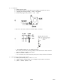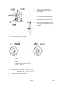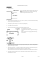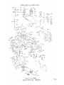
1
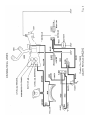
SERVICE MANUAL
23800
MX
Disassembly procedure
1. Peel off Body coverings (A19 & A20)
2. Remove Bottom cover (A400), Connector seat (A34) and Tripod screw (All).
CSS 1.7 x 2.2 x 3, CSM 1.7 x 3.5 x 2
3. Remove Top cover (A300)
a.) Retainer screw (Left handed)
Winding lever assembly (C300)
Cover ring B (A329)
b.) Shutter dial— ASA100, 1/1000
Shutter dial screw (E231) — 23800K-E321A
Shutter dial assembly (0-E223), Hook pin (E228)
Speed dial assembly (0-E229)
c.) Knob assembly (0-D1)
Nut (D12)—23110-D16-1-A
Cover ring (D7)
• d.) Top cover retainer screw (A15 x 2)
CSS 1.7 x 2.2 x 2
Top cover assembly (A300)
4.
Unsolder 7 lead wires
5. Front board plate assembly (A100)
— Not necessary to cock self-timer.
Cover (A24)
0.1mm washers are underneath the Front board plate.
6. Sv resistor assembly (J300)— Retainer screws (E208 x 2)
7. Hot shoe contact (3204) — Hot shoe contact screw (3209 x 2)
8. P.C.board retainer plate (J205) — P.C.board retainer screw (J208), Spring (J206)
23800
1 /36
9.
P.C.board assembly (J500) — CNM 1.7 x 2.5 x 2
Base plate screw (A41-01)
10. Unsolder lead wires. 8 pcs
11. Mirror housing complete assembly (B000)
a.) After loosening Screw (M75), disconnect Idle gear assembly (0-M74) and Supporter plate
assembly (0-M53).
b.) Remove Mirror housing complete assembly (B000) together with Prism seat assembly
(0-M1), Penta prism assembly (0-L3) and Cell frame (J201).
12. Terminal contact assembly (0-J611) — CNS 1.7 x 2.5
13. Battery seat assembly (0-A8) — CNS 1.7 x 2.5 x 2
14. Restitution spring assembly (0-M62)
a.) Idle gear assembly (0-M74), Idle gear supporter plate (M73)
Screw (M75)
b.) Remove Bobbin (M85) — CNL-B 1.4 x 2.0
Without turning brass gear.
c.)
Adjusting plate assembly (0-M68), Pulley seat assembly (0-M76)
Left handed screw (M72)
d.) Restitution spring.assembly (0-M62), Hinge retainer spring (A5)
— CNM 1.7 x 2.5 x 2, W3
15. Governor actuator plate (C252) — Screw (C253), CNL-E 1.7 x 2.5
After removing (C252), install CNL-E 1.7 x 2.5 again.
16. Slow governor assembly (C100) at 1/125 shutter speed.
— CNM 1.4 x 2.0, CNM 1.7 x 2.0
17.
Governor restitution plate (E407), (E408), (E409), W3
18.
Slow speed cam assembly (0-E402), Nut (E406) — 23800K-E406-A
Caution:
a.) Remove Nut (E406) grabbing slow speed cam shaft (E401) with plier, without turning
(E401).
b.) Remove (0-E402) by loosening two set screw, at 1 sec shutter speed.
23800
2 /36
19.
Pinion coupler gear assembly (0-C249) — CNL-E 1.7 x 2.5
20.
Pinion coupler lever assembly (0-C254), (C257) (C 137)
21.
Coupler lever spring (C266).Coupler lever spring hook screw (C214), Cord holder (J525).
22.
Coupler lever assembly (0-C244), Coupler lever retainer screw (C248) — left handed.
23.
Installing seat assembly (0-A508) — CSS 1.7 x 2.2 x 2
24.
SW plate assembly (0-J521) — CNL-D 1.7 x 3.5
25.
Bulb coupler lever spring (C263)
26.
Install Winding lever assembly (C300) with Retainer screw (C305) temporarily, and cock the shutter.
27.
Shutter seat plate assembly (E200) — CSS 1.7 x 3.0 x 3
High speed cam assembly (E210)
Selector gear collar (E123)
28.
Slow speed cam shaft (E401)
LW 17, W70
29.
Winding seat assembly (C100) — Nut B (E144).CNM 1.7 x 3.0, CSS 1.7 x 2.5
30.
Release plate assembly (0-A502) — CNL-D 1.4 x 2.0
Shutter actuator plate A assembly (0-A504)
31.
Shutter rod spring (A514)
Shutter rod assembly (0-A501)
32.
Self-timer (H100) — CNM 2.0 x 9.0, CNM 1.7 x 3.0
33.
X contact seat assembly (0-J621) — CNS 1.7 x 2.5 x 2
34.
High speed lever assembly (0-E126)
a.) Indication spring (E134)
b.) Nut A (E133)
c.) (0-E126) Indication plate assembly (0-E132)
35.
Bottom winding mechanism
a.) Bottom main gear screw (C265) — left handed
b.) Winding transmission plate (C221)
c.) Bottom main gear retainer plate (C220)
d.) Bottom main gear (C219)
e.) Bottom main gear retainer (C269)
f.) Winding shaft supporter plate (C270) — W24
g.) Winding shaft receptacle (C218)
h.) Spool gear assembly (0-C216) — W16 (0.3t)
23800
3 /36
36. Winding shaft assembly (0-C19)
37. Restitution retainer lever (C22)
a.) Supporter screw (C24)
b.) (C22)
c.) Restitution lever spring (C25)
d.) Collar (C23)
38. Coupler pinion (E11) — Retainer screw (E12)
39. Reversing plate (E111)
a.) C137 — b.) E111 — c.) E112 — W6
40. Intermediate gears
a.) E107 — b.) E106 — c.) E104 — d.) E105 — e.) 0 E101
41. Hook plate (E153)
a.) E154 — b.) E155 — c.) E153 — W1
Top 2nd gear assembly (0-C9)
Top 2nd gear shaft retainer nut (C11)
231K-E111-A or 234K-B83-A
42.
• 43.Bounce stopper (E145)
a.) E147 — b.) E146 — c.) E145 — W3 — d.) E152
44.
Shutter curtain light seal (A17)
After releasing the shutter, remove (A17)
— CNS 1.7 x 2.5 x 2
45.
Curtain stopper (E139)
a.) After releasing curtain tension, remove Worm (E41 x 2)
b.) Worm wheel (E42 x2) — left handed.
c.) Curtain stopper screw (E143) — 23800K-E143-A
d.) Curtain stopper retainer screw (E142)
e.) (E140), (E141)
f.) Not removing Curtain stopper (E139), retain it with (E142)
46.
Shutter curtains
a.) (C27) & (C28)
b.) Curtain plate assembly (0-A25)
c.) Shutter curtain mechanism
0-C1, 0-E36, 0-E38, etc.
47.
Top shaft receptacle (C17)
Stopper retainer screw (C18) — CNS 1.7 x 1.8 x 2
48.
Idle gear (C624) — CNL-F 1.7 x 1.8
49.
Bottom shaft receptacle (C202)
W73, CNS 1.7 x 1.6 x 2, CNS 1.7 x 2.5
23800
4 /36
50.
Coupler gear assembly (0-C222)
Coupler gear retainer screw (C226) — left handed
51.
Rewinding actuator lever assembly (0-C241)
a.) CNL-B 1.4 x 2.0
b.) Spring retainer.(C243)
c.) Rewinding actuator lever spring (C242)
d.) 0-C241
52.
Bottom mec.plate assembly (C200)
a.) Stopper pole (C267) — CNS 1.7 x 2.5
b.) Coupler guide (C268)
c.) C200
d.) Sprocket (C236)
23800
5 /36
Assembly procedure
1.
Bottom mec.plate assembly (C200)
a.) Sprocket (C236)
b.) Bottom mec.plate assembly (C200) — positioning with (C202)
c.) C268, C267, CNS 1.7 x 2.5
2.
Spool
a.) Install spool (0-C20) and Spacer (C29)
b.) Top shaft receptacle (C17-01)
c.) Bottom shaft receptacle (C202)
Vertical clearance of Spool is adjusted with W73
(t=0.5 or 0.6mm)
d.) Idle gear (C264)
3.
Rewinding actuator lever assembly (0-C241)
As shown in Parts list
4.
Coupler gear assembly (0-C222) — (C226) = left handed
a.) Sprocket teeth is positioned as shown in Figure
b.) When installing Coupler gear assembly (0-C222), it should be positioned as shown below,
besides sprocket teeth should not be moved.
5.
Shutter curtains
a.) Top mec.plate assembly (0-C1) — C27, C28
Curtain strings should not be off from rollers.
b.).Curtain plate assembly (0-A25)
Arrangement of both curtains is opposite from SP type camera.
6.
Worm (E42) and Worm wheel (E41)
Turn worm wheel two rounds to give the tension to both curtains.
7.
Check 2nd curtain position after releasing 1st curtain
a.) Install High speed lever assembly (0-E126) temporarily.
Cock the shutter, and release 1st curtain, 2nd curtain should be staying at 5mm distant
from picture frame.
Shutter cocking tool — 23800K-E113, E124-A.
23800
6 /36
b.)
When both curtains are wound and hooked with 1st curtain ratchet assembly (0-E135), adjust the
clearance at 0.1mm between high speed.lever and Bottom selector gear assembly (0-E124) with
turning Adjusting stud (E122).
8.
Curtains overlapping
After cocking the shutter, both curtains should be overlapping completely or within ± 0.1mm
deviation.
9.
Bounce stopper (E152)
E152 — W3 — E145 — E146
10. Curtain stopper (E139)
E139 — E140 — E142 — E143 — 23800K — E143-A — E147
11. Top 2nd gear assembly (0-C9)-C11
12. Coupler pinion (E11) — E12 before cocking the shutter.
13. Restitution retainer lever (C22)
C23 — C25 — C22 — C24
14. Winding shaft assembly (0-C19-01)
a.) Clearance between (C22) and (0-C19-01) should be 0.4mm
23800
7 /36
b.) Bottom winding mechanism
W16 — 0-C216 — C218 — W24 — C270 — C269 — C219 — C220 — C221 — C265
(left-handed)
Caution;
* W16 should be installed first separately from (C216), otherwise (C216) can not be installed
together with W16.
* When (C219) is installed, sprocket teeth should be positioned correctly as mentioned before.
Perforation is adjusted definitely here.
15.
Reversing plate (E111) and hook plate
a.) E112 — C26 — W6 — E111 — C137
Check the function and play of (E111), the play should be
within 0.1mm
b.) W1-E153 — E155 — E154
16. Intermediate gears
— Shutter cocked
a.) Sprocket teeth should be positioned correctly as mentioned before.
b.) b.) 0-E101
c.) Spill (E105)
d.) E104
Clearance between (E104) and (E105) should be desirably closer to (0), but (E105) must move up and
down smoothly without catching (E104).
23800
8 /36
17.
High speed lever assembly (0-E126)
— 0-E126 — 0-E132 — E133 — E134
* After installing the above parts, 1st curtain ratchet assembly (0-E135) functions
automatically.
18.
X contact seat assembly (0-J621) — CNS 1.7 x 2.5
19.
Self-timer (H100) — CNM 2.0 x 9.0, CNM 1.7 x 3.0
* Install self-timer pushing upper left.
20.
Shutter actuator plate A assembly (0-A501)
0-A501 — A514 — 0-A502 — 0-A504 — CNL-D 1.4 x 2.0 x 3
21.
Winding seat assembly (C100)
— together with winding lever
— Back cover open.
* Confirm the position of transporting claw before installing as shown in figure.
* Straight parts of transporting claw should align with the center of Nut B (E144) with shutter
cocked and back cover close.
* Check counter dial movement, counter dial should be transported till 37 point, not 38. If
counter dial proceeds till 38 point, reinstall Winding seat assembly (C100) as mentioned
above.
* After cocking shutter, check the clearance between Curtain stopper (E139) and Top selector
gear assembly (0-E113), 0.1mm is enough.
23800
9 /36
22.
Slow speed cam shaft (E401)
E401 — E405 — LW17 x 3 — W70
* Up and down play of (E401) should be within 0.1mm.
23.
Shutter seat plate assembly (E200)
a) Cock the shutter
b) Put on selector gear collar (E123)
c) High speed cam assembly (0-E210)
d) Install (E200) taking care of jointing part with slow speed cam shaft.
24.
Bulb coupler lever spring (C263)
25.
Switch plate assembly (0-J521) Main SW
— CNL-D 1.7 x 3.5 x 2
* When installing it, take care of shortage or leakage to camera body.
26.
Installing seat assembly (0-A508) — CSS 1.7 x 2.2 x 2
27.
Coupler lever assembly (0-C244)
a) Cord holder (J525) — Coupler lever spring hook screw (C214)
b) (0-C244) — Coupler lever retainer screw (C248) — left handed
c) Coupler lever spring (C266)
d) Check the function of (0-C244)
28.
Pinion coupler lever assembly (0-C254)
W70 — 0-C254 — C257 — C137
29.
Pinion coupler gear assembly (0-C249)
* After installing (0-C249), (0-C254) should not touch to (0-C249).
See Figure (a)
* After winding up, the least clearance (0.1 — 0.2) is necessary between the rivet of
(0-C249) and the lever of (0-C254).
See Figure (b)
23800
10 /36
30. Slow speed cam assembly (0-E402)
a) Shutter speed at B
b) Small rivet of (0-E402) should align straight with the center of (E401) and sprocket shaft
as shown in Figure, and fasten Nut (E406) catching (E401) with pliers.
Fasten set screws also.
* When (E406) is fastened without catching (E401) with pliers, jointing split part underneath (E200)
spreads with revolving power of (E401), and slower shutter speed will be affected.
31.Governor (G100)
— CNM 1.7 x 2.0, CNM 1.4 x 2.0
a) Shutter speed at 1/125
b) Install (G100) without bending small levers (such as angle lever etc).
32.
Governor actuator plate (C252)
a) Shutter speed at B
b) Cock the shutter
c) (C252) — (C253) x 2 as shown in Figure
33.
Shutter curtain light seal (A17)— CNS 1.7 x 2.5 x 2
23800
11 /36
34.
Tv indication
a) Shutter speed at 1/1000
b) Lower pulley of Pulley seat assembly (0-M76) should be in parallel with camera.
c) Adjusting plate assembly (0-M68) — (M72) = left handed
d) Restitution spring assembly (0-M62) — (A5) — (M85)
* Turn wire 1 turn counter-clockwise around the pulley of (0-M62)
* After installing (0-M62), Tv wire should not be loose.
•If it is loose, give tension by moving (0-M68), but too much tension makes it harder to
adjust the position of Indication plate (M61).
e) (M73) — (0-M74) — (M75)
* Gear of (0-M62) and (0-M74) should be gearing not too deep, and check the function.
35.
Mirror housing complete assembly (B000)
a) Battery seat assembly (0-A) — CNS 1.7 x 2.5 x 2
b) (B000) should be installed taking care of coupling two gears (M74) and (0-M53).
c) (E407) — (E408) — (E409) — W3
23800
12 /36
36.
Terminal contact assembly (0-J611)
Soldering lead wires 8 pcs.
37.
Shutter speed adjustment
a) Curtain speed
12.2 — 12.3ms
Same way with SP camera.
b) High speed adjustment 1/1000 — 1/60ms
Same way with SP camera
c) Slow speed adjustment 1/30 — l sec
1 Loosen screw
2 Adjust with eccentric screw
3 Fasten screw
4 Apply red lacquer on screw
38.
Shutter stroke
— Shutter dial at B
a) Install Top cover assembly (A300) and Winding lever assembly (C300) temporarily.
b) Depressing shutter button gradually, shutter starts working at 2.1 ± 0.2mm from origina1
position.
c) Self-timer exposure time adjustment at B.(Around 1000ms)
39.
Main SW keep adjustment
Main SW stroke
— 0.6 ± 0.2mm
40.
Tv indication
a) Shutter speed at 1/1000
b) Positioning adjustment of Supporter plate assembly (0-M53).
23800
13 /36
1
2
3
4
41.
Front board plate assembly (A100).
Mechanical back
Tv indication dial should be set just
center portion of viewing finder.
Tv indication (1000) should be set as
shown in Figure.
Three jointing gears (0-M53), (0-M62)
and (0-M74) must function well.If they
do not, adjust the position of Idle gear
supporter plate (M73) with eccentric
screw A
Each figure of Tv indication must come
in the center portion, adjusting eccentric
screw B
45.46mm
42.
Sv resistor assembly (J300) — (E208)
43.
P.C.board assembly (H500)
a.) LED
(A41-01) — W3 — CNM 1.7 x 2.5 — CNL-D 1.4 x 2.5
b.) GPD
(J205) — (J206) — (J208)
c.) Bonding (J500) to Penta prism cover
d.) (J204) — (J209) x 2
44.
Soldering lead wires — 7pcs
45.
Bottom cover assembly (A400) — CSS 1.7 x 2.2 x 3
Tripod screw (All) — CSM 1.7 x 3.5 x 2
46.
Adjustment of LED indication place
23800
14 /36
47.
Light measurement
a.) Temporary setting — Top cover tool, shutter dial, winding lever
b.) Battery checker — VR A
EV12, f8, 1/60, ASA100
2.6V
Light off
2.7V
Light on
c.) Light measurement — VR B or VR C
EV12, f8, 1/60, ASA 100, 2.8V
When shutter dial is turned 1EV step (1/60 — 1/30 and A/60 — 125), and both red LED
(over and under) light on, it shows within 0.1EV difference.
d.) Confirmation of voltage reliability
EV12, f8, 1/60, ASA100
When voltage is dropped down from 2.8V to 2.7V, LED indication should not change.
e.) When mirror stays up, LED should not light on.Check it at B.
48.
Focusing adjustment
a.) Removing Top cover tool and others
b.) Adjust focusing with Focusing screw (M6) x 4
49.
Adjustment of Focusing plate holder assembly (0-B101)
If vertical play is felt on (0-B101), remove Cover plate (B109) and adjust the position of
Hook metal assembly (0-M107) with eccentric screw.
50.
Top cover assemb1y (A300)
Winding lever, shutter dial, rewind knob and other small parts.
Tools — 23110K-D16-1-A
23800K-E231-A
23600K-C135-A
51.
Bonding Coverings (A19 & A20)
23800
15 /36
ASAHI PENTAX MX (23800)
Curtain assembly
1. Curtain inspection
Check if Aron-alpha is applied to curtain string as shown in
Figure.
Aron-alpha is applied to increase durability.Curtain string
should be, bent parallel with shutter curtain.
2.
Install 1st and 2nd pinion shafts (0-E2, 0-E7), (0-E118), (0-E108), (0-E135) and 2nd curtain assembly
(0-E38) to Top mec.plate assembly (0-C1).
3.
Install Top mec.plate assembly (0-C1) to camera body temporarily.
4.
Give slight tension to 2nd curtain.
5.
Install 1st curtain assembly (0-E36) and Curtain plate assembly (0-A25).
Give slight tension to 1st curtain.
Arrangement of both curtains is opposite from SP type
camera.
Install 1st curtain (0-E36) engaging 2nd curtain string
with the rollers.
6.
Removing Top mec.plate assembly (0-C1) from camera body for a while, engage 1st curtain string with
the 2nd curtain pinion rollers and re-install Top mec.plate assembly (0-C1) to camera body without
slipping off the string from rollers.
7.
2nd curtain hold position — with shutter cocked 2nd curtain should stay at 5mm distant from picture
frame when High speed lever hooks Bottom selector gear assembly (0-E124).
Adjust the position of 2nd curtain with changing the coupling between 2nd pinion gear and (0-E124).
8.
Install Top selector gear assembly (0-E113) with shutter released, facing the retainer screws of 1st
curtain pinion 45° forward.
23800
16 /36
9.
Install adjusting plate (E120) and other parts.
Adjusting plate (E120) is installed after
turning Top selector gear and Selector
retainer (0-E118) to cocked position.
10. Install 1st curtain string to bobbin (E3).
Confirm curtain overlapping and slit parallel, with adjusting the
length of 1st curtain string.Aron-alpha is applied to curtain string
and its retainer screw (CNS 1.4 x 1.6) after adjustment is finished,
and cut the curtain string after turning around the Bobbin one time
on the other way.
11. Clearance between Bottom selector gear assembly (0-E124) and High speed lever assembly (0-E126)
should be adjusted at 0.1mm with cocked position by turning Adjusting plate (E120).
After adjustment, apply aron-alpha to Retainer screw (E121).
23800
17 /36
LIST OF SERVICE PARTS
Product No.23800
ASAHI PENTAX MX
Note:
1.
The parts with numbers starting ‘0-’ are assemblies.
2.
0nly available parts are listed below.
Parts No.
Description
A1
Body proper
1
A2
Hinge
1
A3
Hinge collar
2
A4
Hinge retainer plate
1
A5
Hinge retainer spring
1
A6
Back cover guide screw
1
A7
Cassette receptacle
1
Battery seat assembly
(A8, A9, A10 x 2)
1
Tripod screw
1
Strap hook assembly
(A13-01, A14)
1
A15
Top cover retainer screw
2
A16
Mirror box retainer screw
2
A17
Shutter curtain light seal
1
A18
Light seal
1
A19
Body covering, left
1
A20
Body cuvering, right
1
A24
Cover
1
Curtain plate assembly
(A25, M7 1 x2)
1
A27
Sprocket shaft receptacle
1
A31
Light seal A
1
A32
B
1
A33
C
2
A34
Connector seat
1
Connector base plate assembly
(A35, A36 x3)
1
Insulation plate
1
0-A8
A11
0-A13-01
0-A25
0-A35
A37
Quantity
23800
Interchangeability
23602-A23
22 /36
Parts No.
Description
Quantity
Interchangeability
A38
Connector retainer screw
1
A41-01
Base plate screw
1
A42
Spacer
1
A43-01
Light seal curtain
2
A44
A45
A46
A47
Light seal D
Light seal E
Light seal F
Light seal G
2
2
1
1
A48
Strap hook retainer screw
2
A49
Light seal tape
1
A100
Front board plate assembly
(A101 — A149, 0-J401, 0-J601 x 2)
1
A104
Mount ring
1
A105
Mount spring
1
23602-A105
A106
Mount screw
6
23602-A106
Mount lock button assembly
(A108, A107, A109)
1
A110
Collar
1
A111
Lock button spring
1
A112
Lock pin supporter plate
1
A113-01
Front board retainer screw
4
23602-A159
A114
Front board light seal
1
23701-A120
A116-01
Front board light seal
2
A121-01
Base plate
1
Charge lever assembly
(A123, A122-01, A124)
1
Charge lever shaft A
1
Charge lever shaft B assembly
1
0-A108
0-A123
A125-01
0-A127-01
(A127-01, A145)
A130-01
Button cover
1
A132
Start button
1
A134
Spring B
1
Diaphragm coupler ring assembly
(A135, A136 x 5, A137 x 5, A138, A140)
1
Diaphragm coupler ring spring
1
Supporter plate assembly
(A143, A144, A146, A147, A148-01)
1
0-A135
A139-01
0-A143
23800
23 /36
Parts No.
Description
Quantity
A148-01
Restitution spring
1
A149
Front board light seal
1
A200
Back cover assembly
1
(A201, A203, A207, A208 x 2, A209, A210 x4, A211,
A212, A213, A214, A215, A216 x 4, A217 x 2, A218
A219, A221, A222-01 x 4, A225, A226, A227)
A202
Back cover shaft receptacle
0-A204
Interchangeability
2
Pressure plate assembly
(A204, A205, A206 x 2)
A217
A218
Light seal A
Light seal B
2
1
A220
Pressure plate cover
1
A300
Top cover assembly
(A301 — A336)
1
A302
Accessory shoe
1
A303
Accessory shoe spring
1
Accessory shoe base assembly
(A304, A305)
1
A306
A307
Contact spring A
Contact spring B
1
1
A308
Collar
1
A309
Retainer screw
1
A310-01
Insulation washer
1
A311
SW pin
2
A312
Indication plate
1
A315
Cover ring A
1
Shutter button seat assembly
(A316 ,A317)
1
A318
A319
Guide screw A
Guide screw B
1
1
23602-A317
23602-A318
A320
Spring
1
23602-A320
A322
Nut
1
Click plate assembly
(A323, A324)
1
Shutter button
1
Shutter button core assembly
(A326.A327, A328)
1
Cover ring B
1
0-A304
0-A316
0-A323
A325
0-A326
A329
23800
23701-A220
23602-A327
23701-A307
24 /36
Parts No.
Description
Quantity
A330-01
Window C
1
A332-01
Mask
1
A334-01
Pattern retainer
2
A335
Light seal
1
A336
Insulation tape
2
A400
Bottom cover
(A401, A406)
1
A403
Bottom winding cap
1
0-A405
Battery cap assembly
(A405, A406)
1
0-A501
Shutter rod assembly
(A501, A505, A507)
1
0-A502
Release plate assembly
(A502, A503, A506, A516)
1
0-A504-02
Shutter actuator plate A assembly
(A504-02, A515-02, A516, CNL-D 1.4 x 2.5)
1
0-A508
Installing seat assembly
(A508, A509, A510, A511, A512, A513, LW13)
1
A514
Shutter rod spring
1
B000
Mirror housing complete assembly
(B1 — B112, 0-J531-01, 0-J532-02)
1
Mirror seat assembly
(B2, B3, B4, B5, B6 x 4, B7)
1
Spacer
1
0-B9
Supporter, right assembly
(B9, B10)
1
0-B11
Supporter left assembly
(B 11, B12)
1
Mirror seat restitution spring
1
Mirror actuator lever, bottom assembly
(B15, B16, B17, B18 x 2, B19, B46)
1
Washer
1
0-B2
B8
B13
0-B15
B20
0-B22
23602-0-A403
Diaphragm coupler lever assembly
1
(B22, B21, B23, B24 x 2, B25-01, B26-01, B29, B30, B31-01, B32-01, B33, B34)
828
Diaphragm actuator lever connection spring
1
B35
Hook plate
1
B36
Hook plate spring
1
Actuator lever plate assembly
(B41-01, B40-01)
1
0-B41-01
Interchangeability
23800
25 /36
Parts No.
Description
Quantity
B51-01
Stopper screw
1
B53
Diaphragm actuator lever spring
1
0-B55-01
Mirror actuator plate assembly
(B55-01, B56, B57, B58, B93)
1
0-B59
Mirror charge lever assembly
(B59, B60, B61, B62, B63.)
1
0-B64
Mirror charge lever retainer assembly
(B64, B65)
1
B66
Mirror charge lever collar screw
1
B67
Restitution spring
B68
Mirror seat spring
0-B71
Shock absorber assembly
(B71, B72, B73)
1
0-B79
Mirror charge hook plate assembly
(B79, B80)
1
Hook plate spring
1
Mirror seat receptacle assembly
(B83, B88)
1
Mirror seat receptacle screw
1
Mirror seat receiver assembly
(B85-01, B86)
1
B87
Mirror seat recever spring
1
B89
Light seal frame
1
B90-01
Mirror shock absorber
1
B91
Mirror adhesive tape
1
B92
B94
B95
Light seal A
Light seal B
Light seal C
1
1
1
B96
Stopper washer
1
Focusing plate holder assembly
(B 101, B 102)
1
B103
Shaft receptacle
1
B104
Spacer
1
B105
Shaft
1
Hook metal assembly
(B 107, B108)
1
B109
Cover plate
1
B110
Retainer screw
2
B81
0-B83
B84
0-B85-01
0-B101
0-B107
23800
Interchangeability
23701-B70
26 /36
Parts No.
B111
B112
Description
Quantity
Light seal curtain
Light seal curtain B
1
1
0-C1
Top mec.plate assembly
(C1, C2, C3, C4 x 2, C5, C6, C7, C8, E5)
1
0-C9
Top 2nd gear assembly
(C9, C10)
1
G11
Top 2nd gear shaft retainer nut
1
C17-01
Top shaft receptacle
1
C18
Stopper retainer screw
1
0-C19-01
Winding shaft assembly
(C19-01, C12, C13, C14, C15-01, C16)
1
0-C20-01
Spool assembly
(C20-01, C21 x 16, C30)
1
C22
Restitution retainer lever
1
C23
Collar
1
C24
Supporter screw
1
C2S
Restitution lever spring
1
C26
Winding plate supporter
1
C27
Top cover supporter
1
C28
Top mec. plate screw
1
C29-01
Spacer
1
C100
Winding seat assembly
(C101 — C142)
1
C200
Bottom mec.plate assembly
(C201 — C215, C262, E6, E15, E44)
1
C214
Coupler lever spring hook screw
1
Spool gear assembly
(C216, C217)
1
C218-01
Winding shaft receptacle
1
C219-01
Bottom main gear
1
C220-01
Bottom main gear retainer plate
1
C221-01
Winding transmission plate
1
Coupler gear assembly
(C222, C223, C224, C225 x 2)
1
C226
Coupler gear retainer screw
1
C227
Sprocket gear
1
C228
Sprocket retainer
1
C229
Sprocket shaft
1
0-C216
0-C222
23800
Interchangeability
27 /36
Parts No.
Description
Quantity
Interchangeability
C230
Clutch ring
1
C231-02
Clutch ring retainer screw
1
23602-C14
C232-01
Clutch ring retainer screw collar
1
23602-C15
C233
R button
1
C234
Sprocket spring
1
C235
Sprocket collar
1
C236
Sprocket
1
Rewinding actuator lever assembly
(C241, C237, C238, C239, C240)
1
C242
Rewinding actuator lever spring
1
C243
Spring retainer
1
Coupler lever assembly
(C244, C245, C246, C247)
1
Coupler lever retainer screw
1
Pinion coupler gear assembly
(C249, C250)
1
C252
Governer actuator plate
1
C253
Governer actuator plate screw
2
Pinion coupler lever assembly
(C254, C255, C256)
1
C257
Pinion coupler lever spring
1
C263
Bulb coupler lever spring
1
C264
Idling gear
1
C265
Bottom main gear screw
1
C266
Coupler lever spring
1
C267
Stopper pole
1
C268
Coupler guide
1
C269
Bottom main gear retainer
1
C270
Winding shaft supporter plate
1
C300
Winding lever assembly
(C301, C302, C303 x 4, C304, TCSM 1.4 x 3.5)
1
C305
Retainer screw
1
Knob assembly
(D1, D2, D3, D4, D5, D6)
1
Cover ring
1
Shaft receptacle assembly
(D8, D9, D11)
1
0-C241
0-C244
C248
0-C249
0-C254
0-D1
D7
0-D8
23800
23602-C11
23701-C18
28 /36
Parts No.
Description
Quantity
Interchangeability
D10
Rewind shaft
1
D12
Nut
1
1st curtain pinion shaft assembly
(E2, E1)
1
E3
Bobbin
2
E4
Retainer screw
3
2nd curtain pinion shaft assembly
(E7-01, E1)
1
E11
Coupler pinion
1
E12
Coupler pinion screw
1
E15-01
Roller A
2
E24
Roller B
2
E26
1st curtain shaft collar
1
0-E36
1st curtain assembly
(E36, E20, E21, E22, E23, E24, E25, E35, E37)
1
0-E38-01
2nd curtain assembly
1
(E38-01, E4, E8, E9, E10, E27, E28, E29, E30, E31, E32, E33, E34, E35, E39)
0-E2
0-E7-01
E40-01
Bottom shaft rest
1
E41
Worm
2
E42
Worm wheel
2
E46
Collar
2
Intermediate gear, bottom assembly
(E101-01, E102, E13)
1
E104
Intermediate gear, top
1
E10S
Spill
1
E106
Spill retainer plate
1
E107
Intermediate gear retainer screw
1
E108
Spill spring
1
E109
E110
Spill spring screw A
Spill spring screw B
1
E111
Reversing plate
1
E112
Reversing spring
1
0-E113
Top selector gear assembly
(E113, E114, E115 x 2, E116, E117)
1
0-E118
Selector retainer assembly
(E118, E119)
1
Adjustable plate
1
0-E101-01
E120
23800
29 /36
Parts No.
Description
Quantity
Interchangeability
E121
Adjustable plate screw
1
E122
Adjusting stud
1
E123
Selector gear collar
1
0-E124
Bottom selector gear assembly
(E124,E115, E125)
1
0-E126
High speed lever assembly
(E126, E127, E128, E 129, E130, E131, E137)
1
0-E132
Indication plate assembly
(E132, E138)
1
E133
Nut A
1
E134
Indication spring
1
1st curtain ratchet assembly
(E135, E136)
1
E139
Curtain stopper
1
E140
Lubrication tube retainer
1
E141
Lubrication tube
1
E142
Curtain stopper retainer screw
1
E143
Curtain stopper screw
1
E144
Nut B
1
E145
Bounce stopper
1
E146
Bounce stopper screw
1
E147
Bounce stopper spring
1
Synchro actuator plate assembly
(E148, E149, E150)
1
E151
Synchro actuator spring
1
E152
Bounce adjusting screw
1
E153
Hook plate
1
E154
Hook plate screw
1
E155
Hook plate restitution spring
1
E200
Shutter seat plate assembly
1
(E201, E202, E203, E204, E205, E206, E207, E208, E209-01, E212, E232)
0-E135
0-E148
0-E210
High speed cam assembly
(E210, E211)
1
0-E223
Shutter dial assembly
(E223, E224)
1
Hook pin
1
E228
0-E229
23701-E276
Speed dial assembly
1
(E229, E221, E222 x3 , E225, E226 x 3, E227, E229, E230)
23800
30 /36
Parts No.
Description
Quantity
E231
Shutter dial screw
1
E401
Slow speed cam shaft
1
Slow speed cam assembly
(E402, E403, E404)
1
E405
Spacer
1
E406
Nut
1
E407
Governor restitution plate
1
E408
Restitution plate shaft
1
E409
Restitution plate spring
1
G100
Governer
1
H100
Self-timer
1
J201
Cell frame
1
J203
Light metering lens
2
J204
Hot shoe contact
1
J205
P.C.board retainer plate
1
J206
Spring
1
J207
Mask
1
J208
P.C.board retainer plate screw
1
J209
Hot shoe contact screw
2
J300
Sv resistor assembly
(J301 — J307)
1
J400
f-volume assembly
(J401, J402)
1
J403
Collar
2
J500
P.C.board assembly
(J501, J502, J503, J504, J506, J507-01)
1
J508
Adhesive tape
1
SW plate assembly
(J521, J522, J532-01, J524 x 2)
1
J525
Cord holder A
1
J526
Cord holder
4
J527
Relay P.C.board
1
J528
Relay P.C.board
1
0-J531-01
SW plate A assembly
(J531-01, J533-01, J535-02, J537, J613 x 4)
1
0-J532-02
SW plate B assembly
(J532-02, J534-02, 3538, 1613 x 2)
1
0-E402
0-J521
23800
Interchangeability
23723-C419
23602-N15
23700-J507
23700-J206
23701-A157
31 /36
Parts No.
J539
Description
Quantity
Adhesive tape
0-J601
Synchro terminal assembly
(J601, 3602, J603)
2
0-J611
Terminal contact assembly
(J611, J612 x2, J613 x4)
1
0-J621
X contact seat assembly
(J621, J622, J623, J624, J625 x 4)
1
L1
Mirror
1
L2
Fresnel lens
1
0-L3
Penta prism assembly
(L3, L6-01, M11)
1
0-L4
Eyepiece assembly
(L4, L5)
1
Prism seat assembly
(M1, M2 x 2, M3 x 2, M4 x 4, M5, M10)
1
M5
Ground glass mask
1
M6
Focusing screw
4
Receptacle plate assembly
(M7, M8 x 4, M9 x 4)
1
Penta mask
1
0-M12
Penta retainer plate A assembly
(M12, M14)
1
0-M13
Penta retainer plate B assembly
(M13, M14)
1
M15
Prism protector
1
M16
Penta retainer plate
2
M17
Penta retainer plate tape
2
M51
Seat
1
M52
Cover plate
1
Supporter plate assembly
(M53, M54, M55, M56, M57, M58, M59, M60, M61)
1
Indication plate
1
0-M1
0-M7
M10
0-M53
M61
Interchangeability
0-M62
Restitution spring assembly
1
(M62, M63, M64, M65, M66, M67, M82, M84, M86)
0-M68
Adjusting plate assembly
(M68, M69, M70)
1
M72
Adjusting plate screw
1
M73
Idle gear supporter plate
1
23800
32 /36
Parts No.
Description
0-M74
Idle gear assembly
(M74, M83)
1
Screw
1
Pulley seat assembly
(M76, M77, M78, M79, M80, M81)
1
M85-00A
Bobbin A
1
-00B
Bobbin B
M75
0-M76
Quantity
23800
Interchangeability
33 /36
LIST OF STANDARD PARTS
Product No.23800
ASAHI PENTAX MX
Small screws:
Description
Surface treatment
Position of use
Quantity
Set T 1.2 x 2
Black nickel
M62, M67
1
Set T 1.4 x 1.8
“
E402, E401
2
Set T 1.7 x 2.2
“
E40, E41
2
Set F 1.4 x 2.5
“
E129,E137
1
Set F1.7 x 3.5
“
A1
1
CNS 1.4 x 1.4
“
E113, E120
2
CNS 1.4 x 1.6
“
A506, A501
1E3, E37
1
2
CNS 1.4 x 2
“
G100, G201
1
CNS 1.7 x 1.5
“
A17, A1
2
CNS 1.7 x 1.6
“
C202, C201
2
CNS 1.7 x 1.8
“
C17,A 1
2
CNS 1.7 x 2
“
A112, A101
D8, A1
J531, B1
L3M1
2
3
2
2
CNS 1.7 x 2.5
“
A135, A101
A8, A1
M51, B1
C202, A1
J621, A1
C201, A1
2
2
2
1
2
1
CNS 1.7 x 3.5
“
B89, B1
4
CNM 1.4 x 2.5
“
D6, D1
2
CNM 1.7 x 2
“
A61, A1
A25, A1
C100, A1
2
2
1
CNM 1.7 x 2.5
“
C201, A1
M62, A5, A1
J612, A1
J501, A41, A1
1
2
1
1
CNM1.7 x 3
“
A35, A1
H100, A1
C101, A1
1
1
1
CNM 1.7 x 4
“
B1, A1
2
CNM 2 x 9
“
H100, A1
1
23800
34 /36
Small screws:
Description
Surface treatment
Position of use
Quantity
CSS 1.4 x 3
Black nickel
A143, A125
3
CSS 1.7 x 2
“
B11, B1
2
CSS 1.7 x 2.2
Nickel
A401, A1
A301, A1
B103, B1
A508, A1
3
2
2
2
Blacknickel
CSS 1.7 x 2.5
“
B9, B1
E201, A1
E201, C7
2
2
1
CSS 1.7 x 2.8
“
A202, A1
4
CSS 1.7 x 3
“
A2, A3, A4, A1
A302, A301
C26, C101
E40, A1
2
2
1
2
CSS 1.7 x 6.5
“
A302, A301
2
CNM 1.7 x 3.5
“
A11, A1
2
T-CSM 1.4 x 3.5
Nickel
C304, C301
1
CNL-B 1.4 x 1.5
Black nickel
B107, B1
M53, B51
2
2
CNL-B 1.4 x 2
“
M85, E209
C241, C206
1
1
CNL-D 1.4 x 1.6
“
E135, C6
A515, A504
C134, C101
1
1
1
CNL-D 1.4 x 2
“
C142, C101
A504, A501
1
2
CNL-D 1.4 x 2.5
“
A502, A501
1
“
J501, M75
1
“
B15, B20
B46, B45
B79, B74
1
1
1
B83, B1
1
“
M12, B1
M13, B1
1
1
CNL-D 1.7 x 3
“
J521, A1
2
CNL-D 1.7 x 4
“
J403, J401, A101
2
CNL-E 1.7 x 2.5
“
C249, C210
1
A127, A123
1
Small screws:
CNL-D 1.4 x 3
CNL-D 1.7 x 2
CNL-D 1.7 x 2.5
CNL-E 1.7 x 3.5
23800
35 /36
Small screws:
Description
Surface treatment
Position of use
Quantity
CNL-F 1.7 x 1.8
Black nickel
C264, C205
1
J201,B1
2
E229, E230
3
CNL-F 1.7 x4
CRSS 1.4 x 1.6
“
(PB-5)
Washers:
Description Material
Thickess
Position of use
Quantity
W1
0.07, 0.1mm
0.3, 0.4
M57, M60
E153, A1
1
1
0.1, 0.15
B83, B85
1
“
0.3
A135, A101
2
Steel
0.3
E145, A1
1
Brass
0.15, 0.2, 0.25, 0.3
AS, M62
2
0.2
J501, A41
1
0.1
C136, C105,
C126, C128
C134, C101
E111, C4
A143, A144
E402, E401
M62, M63
1
1
1
1
1
1
1
Brass
W2
W3
W6
Stainless
0.03, 0.05, 0.07,
0.01, 0.15, 0.2
W7
Brass
0.05, 0.1, 0.15, 0.2
A101, A1
1
W14
“
0.03, 0.05, 0.1
0.1, 0.15
M62, M63
B41, B39
1
1
0.3
C202, C216
1
W16
W22
“
0.2, 0.3, 0.4
0.1, 0.15, 0.2, 0.3
C204, C227
C141, C112
1
1
W24
“
0.1, 0.15, 0.2
C270, C218
1
W28
“
0.3
C229
1
W40
“
0.1, 0.15
B74, B75
1
W62
“
0.1, 0.15, 0.2
0.1
B103, B1
M73, M74
1
1
W63
“
0.05, 0.1
B22, B30
1
W70
“
0.02, 0.03, 0.05
0.1, 0.15, 0.2
0.3
C254, C201
E401
2
1
W73
“
0.5, 0.6
C20
1
W77
“
0.05, 0.07, 0.1
E201, E232
1
23800
36 /36