1
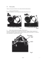
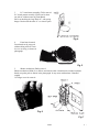
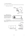
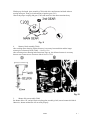
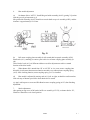
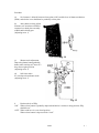
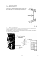
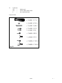
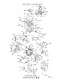
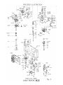
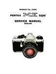
PRODUCT No. 23602
ASAHI PENTAX
SERVICE MANUAL
B.
Disassembly
There are some parts which have to be taken off with careful treatment.
1.
Top cover (A300) removal
Wind lever should be set at closed position before taking off top cover.
AT PREADVANCE ANGLE
Fig. 2
AT CLOSED POSITION
Fig. 1
2.
Photo sensor circuit board assembly (T300) removal
K2 camera is controlled with very small electric current (ex. 200pA or 300pA), therefore all
electric parts should be treated carefully, especially, photo sensor circuit board; it is so sensitive
that it should not be touched with bare hands.
Fig. 3
23602
1
/
3.
P.C. board attern assembly (T100) removal
P.C. board pattern assembly (T100) can be taken
out with or without removing Front Board.
Pull it out hooking the large black I.C. with spring
hanger. Don't touch the other I.C.s or electric parts.
Fig. 4
4.
Front board removal
Front board can be removed
without taking off Self-Timer
lever or covering, as shown in
photograph.
Fig. 5
5.
Shutter mechanism (E000) removal
Shutter mechanism (E000) is so delicate and sensitive that it should not be touched with bare
hands except the parts as shown in the photograph. It may cause malfunctions if handled
roughly.
Use finger cover for removal.
Fig. 6
Fig. 7
23602
2
/
C. Assembly and adjustments
Some parts should be assembled and adjusted. with careful treatment as shown in the following.
1.
Winding stopper assembly (0-C6)
Fig. 8
2.
Winding spring (0-C23)
Face the retainer screw of spring in
the direction of Tripod socket, and
wind the spring a little and stretch it
in the direction of tripod seat. The
proper tension is obtained when it is
stretched around Tripod socket
Fig. 9
3.
Perforation Adjustment
There are several kinds of 2nd gear (C205) which are selected to achieve the proper position of
socket teeth. After removing 2nd gear, set sprocket (C9) in the correct position using the tool
(23600 N-A1, C9-A)
Fig. 10
23602
3
/
Wind up top 2nd mech. plate assembly (C200) with driver and loosen wind shaft without
moving main gear. Then give back-tension to sprocket gear (C16)
Choose the proper coupling 2nd gear (C205) and install it in the above-mentioned way.
Fig. 11
4.
Memory block assembly (T400)
After cocking mirror housing, 02mm clearance is necessary between delrin and the longer
contact piece of memoiy block (T400) — See Fig. 12 A
After releasing mirror housing and when mirror stays up, also 02mm clearance is necessary
between two contact pieces of memory block. See Fig. 12 B
Fig. 12
5.
Shutter dial seat assembly (F000)
Set shutter dial at “B”, and pull meter coupling plate assembly (0-A8) toward counter dial block.
Otherwise, shutter mechanism will not work properly.
23602
4
/
6.
Blue needle adjustment
(a)
Set shutter dial to “AUTO”. Install Idle gear holder assembly (0-A12) gearing 2/3 portion
with the gear of (ga1vanometer (q 1)
Idle gear holder assembly (0-A12) should never touch shaft recept~cle assembly (0-D5), and the
clearance is approximately 0.2-0.3mm.
Fig. 13
(b)
Pull meter coupling plate assembly (0-A8) toward shaft receptacle assembly (0-D5).
Install rack (A11), attaching its concave part to the rivet of meter coupiing plate assembly (0A8).
Three kinds of rack (A11) of different widths are used for adjustment to achieve smooth
function of the blue needle.
(c)
When shutter dial is turned from “B” to “AUTO” or vice versa, meter- coupling plate
attsembly (0-A8) must function must function smoothly even without meter coupling spring
(A15). After checking function, meter coupling spring (A 15) is installed.
(d)
Blue needle is adjusted by moving rack (A11) left -or right, so that blue needle matches
with each step of shutter speed scale when shutter dial is turned.
(e) Apply red lacquer to screws and Plio-Bond to meter coupling spring (A155) after finishing
adjustment.
7.
Stroke adjustment
After putting on top cover (A300) and wind lLever assembly (0-C132), set shutter dial to “B”,
Wind lever should be set at closed position.
23602
5
/
Procedure
(a)
No clearance is allowed between release plate (A503) and the lever of shutter mechanism
(E000). and also the lever should not be pushed by release plate.
(b)
After shutter cocking, adjust
clearance to 0.3mm between Mirror
Actuator lever hook plate assembly
(0-B48) and its hitting part.
(Adjusting screw 1)
Fig. 14
(c)
Shutter stroke adjustment
Depressing shutter button gradually,
shutter starts working at 2.3mm ±0.2
deep from original position.
(Adjusting screw 2)
(d)
Self timer stroke
0.1 mm deeper than shutter stroke
(Adjusting screw 3)
Fig. 15
8.
Funchon check of SWp
“ON” When release button is gradually depressed and before it reaches to keep-position, SWp
should be on”.
“OFF” When wind lever is set at closed position.
When release button is depressed with “Lock”
23602
6
/
9.
Shutter speed adjustment:
Testers: Light value correction unit. TSST-3A. T adjuster (or battery), ESST-1A, digital counter,
diaphragm setting ring (KA-00-lA), 23600K-A400-A.
Fig. 16
Procedure:
(a)
Auto speed adjustable resistor R7
(1X, ASA100, 2.8V)
EV12
—
1/60 sec
EV16
—
1/1000
EV16(2X)
—
1/500
EV8
—
1/4
EV4
—
1
(b)
Meter level — R10
EVI6
—
1/1000sec
(c)
Meter sensitivity — R9
EV8
—
1/4
(d)
Manual shutter speed — Rl2
EVI2
—
1/60
(check all shutter speeds to see Rotary SW contact effects)
(e)
Battery Checker
2.1V
OFF
2.4V
ON
(No adjustment is allowed because no tester is supplied).
Fig. 17
23602
7
/
10.
Galvanometer installation
Tester: Meter tester (MA-00-01)
Needle must be absolutely horizontal between 15 and 8. Check
the movable range of the needle in the upper and lower part.
Fig. 18
11.
Shutter release adjustment
As shown in Fig. 19, when mirror .housing is released, dimension between Shutter Actuator
plate (B61) and minor housing foot. should be kept at 9.4 ±10mm.
The longer Shutter actuotor plate (B61) will break Shutter mechanism (E000), and the shorter
one will never make it (E000) function.
Fig. 19
23602
8
/
D.
Lubricants
G21
—
G31
—
L
—
Mainly used
0-B25, 0-B48, 0-B68, 0-B22
On rewind shaft (D6)
E. Special tools
Fig. 20
23602
9
/