1
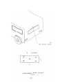
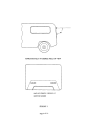
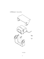
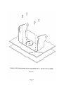
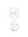
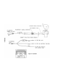
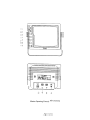
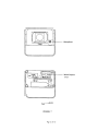
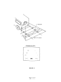
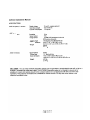
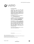
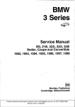
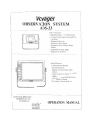
AOS-33
OPERA TIONS
MANUAL
IMPORTANT:
The VOYAGER Observation System (AOS-33) has been designed to provide years of trouble-free operation
Please read
this manual thoroughly.
This manual contains instructions to ease installation of the camera and monitor. The VOYAGER
Observation System is a supple1nentto
standard rearview mirror systems, anlj will provide additional rearview visiun wherl
installed and maintained properly. The VOYAGER Observation system is not intended in any way to be a substitute for
careful, cautious, defensive driving or for the consistent adherence to all applicable traffic laws and motor safety regulations
This product is not intended to be a substitute for rearview mirrors or for any other motor vehicle or boal equipment
mandated by law
FEATURES:
AOC-75 CCD Camera
270,000 pixel image sensor
0.1 Lux sensitivity
Automatic electronic iris provides a clearer, more consistent image in low and bright light
Wide angle lens provides a broad viewing area
Compact design and light weight ease installation in most vehicles, including large boats
Durable, waterproof construction
Built-in microphone for audio pickup
Normal/mirror image switch on back of camera
Wind deflector reduces build up of dirt on lens
Waterproof cable connection
AOM-70 Monochrome
7.0" Monitor
Day/night switch
Brightness and contrast controls
Volume control
Camera Dosition switch for a Danoramic view or a concentrated
Illuminated front panel
Power/stand-by switch
Internal speaker with external speaker jack
CONTENTS
OF 1 COMPLETE
view
SYSTEM:
AOC-75 CCD Camera:
1 -Camera
1 -Camera bracket
4 -Attachment
screws with washers (M4x8)
1 -Wind deflector
AOM-70
7.0" Monochrome
1- 7.0" monitor
1 .Snap-on
Monitor'
sun visor
1 -Monitor
1 -Power
bracket
harness
1 -Range
markers
4 -Thumb
screws
with
locking
connector
(MSx12)
OCA.80 Cable:
1 -20 meter cable with waterproof
connector.
Oil, gas, grease resistant.
Documents:
1- Operations
manual
Page
lofl4
UV stable
AOS.33 Operations
Manual
BEFORE IN5TALLATtON:
1.
This system operates from 10 volts DC to 38 volts DC, negative ground
2.
Please install this system according to the instructions in this manual.
3.
Do not disassemble the camera or the monitor. This voids the warranty
Disassembling the camera Will
compromise the waterproof sea!
Connect the system to an ignition switched power source. Connection to a battery source will reduce battery life
4.
**WARNING**
, .It)
pTeve"1 e\~t:.1f\C'd\
"'\)t)C". DO NO'. oPEN '.HE tAON\TOR CA-SE. There are potentially lethal "Qltage~ in~ide the
monitor. There are no user serviceable parts inside. If evidence of tampering is detected, the warranty will be
2.
~.
considered void.
Keep monitor away from leaking water, rain, moisture etc, It is NOT waterproof, Any moisture inside the monitor
could cause extensive damage,
Use \ne \numbscrews \0 moun\ \he rT1on'l\orto bracket,
**CAUTION**
'\ .DO
NOT OPEN
THE CAMERA
CASE. This will break the camera's
2.
detected. the warranty will be considered void.
Do not molJnt the camera near the lower area of the vehicle
3.
and may cquse physical damage to tne camera
Use only the M4x8 bolts and washers to mount the camera
INSTALlATION
waterproof
(e.g. Bumper).
seal. If evidence
This reduces
of tampering
is
the view of the camera
INSTRUCTIONS
Acc.rs CAMERA
1 .Attach
camera bracket (See Fig 1) to upper portio~ of vehicle. Attachment point must be s'urd)' enough 'I:>suppon
2-
camera and bracket.
Att~ch camera to bracket using M4x8 bolts provided. Adjust angle as indicated in figure 2 (Use rear bumper and
~.
back of vehicle as a reference point
W\tld dei\ectof ma~ 00 \m\a\\~.I"is
Ue"~I:;\Ofis desig"~d \0 r~t\ut:.e \ne bIJi\6 up 0\ du\;\, d\rt and mo\S\uTe
on the camera lens (See Fig 3).
AOM.70 MONiTOR
1.
Att'i1ch monitor ins\;je veh\cle in a location conven\£!nt to the dri~er (e.g. center of dash, overhead or in dash). (See
2.
3.
4.
Fig 4)
Use a compression plate l!) attech the monitor bracket to the dash or overhead (See Fig 4).
Adjust !T\ounting a!)gle of the monitor to allow driver to easily view the screen from all seat positiOn$ (See Fig .5) .
If necessary, snap sun visor into groove on front face of monitor. Press a\l (4) sid£!s of the visor to ~nap it into pl-ace
AOC-80 CABLE
1.
The camera-to-cable connection ia waterproof. The cabJe-to-monitor connection is not waterproof. Be SlJre to
orient the cable pr()perly. The cylindrical end attaches to the camera. The rectangular box end attaches to the
2.
monitor. (See figure 6)
Do not run the AOC-80 cable over sharp edges or corners. Do not kink the cable. Keep the cable away from hot
3.
4.
and rotating parts.
Place all exces-s c-able in convolut~d tubinfJ
Wire tie the cable securely.
Page 2 of 14
AOS.33 Operations
Manual
MAINTENANCE:
Remove dust and dirt with 'd damp ~oft cloth. Heav;er dirt should be removed with a damp soft cloth and mild deteT9~f)t.
Do not use strong cleaning agents containing gasoline, thinner. benzene or alcohol. These substances may damage the
exterior surface of the monitor.
**CAUTION**
,
Before drining, be sure no cable or wiring is on the other side. Be sure to dril1 a '6mm l'518l diame\er'110)e on)y
2
Feed as much cable as possible into vehicle and clamp secur~ly. This reduces the possibility of being hooked
during production.
3.
Keep all cables away from HOT, ROTATING and ELECTRICALLY NOISY components.
4.
To increase protection of cable, place all excess wire and extension cable in convoluted tubing
5.
Do not tWist camera cable and do not cut camera pigtail or cable
WIRING
CAMERA
AND
MONITOR
See wiring diagram for connections to ignition, ground and back-up circuit (See Fig. 6)
Winng camera:
Drill a 19mm(V4;;j!diameter
hole into vehicle body near the camera and bracket.
ConneCTcamera--connector to extension cable in vehicle.
Push extra cable if)to vehicle (Be tQ(eful no1.\0 \t."11)r..
cable) and fIt grl)lTIme\ in\o ho\e.
Apply sealant around grommet to increase resistance to water penetration.
Wiring Monitor:
Insert extension cable into camera #1 position If (2) camerCIs are used, be sure to mark each extension
cable proper\'j '3\"\<ip\ug secol\d cable if\to camera #2 position.
But\dle exce~s c"dble together usit\g a c'3b\~ tie Q( 'li\1'1\tape .lhis 'fi\" "i\'lQi<ipos$ible <iamage to cable.
during operation.
The red Wire marked ACC is connected to an ignition power source, the black Wire marked GNO is
co/)nected to chassis ground. and the blue wire marked BACK is connected to the vehicle's back. up circuit
1
2
3.
4
FUNCTIONS AND OPERATION
Monitor:
1.
Power
2
Camera
3.
Input
switch'
position:
switch:
4. Contrast:
5 Brightness
6. Volume:
7. Day/Night
switch:
STD. BY -Monitor operates when vehicle transmission is switched into ffREVERSE«
ON -Monitor and system operate when ignition switch is "ON"
UP- Panoramic view of the horizon, if camera is in "UP" position
DOWN- Directed view of the rear of the vehicle, if camera is in "DOWN" position
"A." -used mainly for rear mounted camera or as specified by the installer
"8" -used mainly for side or mirror mounted camera or as specified by the installer.
Variable control of contrast. Should be adjusted if the "DAY/NIGHT" switch does not
achieve the most desirable picture.
Variable control 01 brightness. Should be adjusted il the "DA'fJN\GHj" switch does r.Qt
achieve the most desirable picture.
Variable control of internal speaker and external speaker volume.
Pre-set brightness and contrast levels optimized for day and night operation.
-Page 3 of 14 -
AOS-33 Operations
FUNCTIONS
Rear
of Monitor'AND
1 Power
OPERATION,
connection'
2, Camera
3, Camera
4 External
A input
B input
speaker
Manual
CONTINUED
1
not used
2
Ground
3
Reverse
4
5
6
not used
not used
i-12VDC
ignition
connection
COMPONENTS
circuit
wire
-blue
-red
wire
wire
connection
to camera extension
cable
connection
to additional
camera extension
cable
center pin is positive audio output. Used to disable
remotely
CAMERA
-black
mount
a speaker
for driver
the internal
speaker
and
convenience
AND CONTROLS
Camera'
1.
Microphone -waterproof
microphone for audio pickup,
2.
MirrorlNormal switch -waterproof switch to change camera image from a mirror view (rear of vehicle
mounted) to normal view (side or front mounted camera) See Figure 7.
AFFIX'NG
DISTANCE
MARKERS
TO THE MONITOR SCREEN
Clean monitor screen surface of fingerprints. Set the camera into the "OOWNK position Place distance indicators
behind the vehicle at (3) feet, (6) feet and (9) feet along the width of the vehicle. These distances are measured
2.
3
4.
from the rear bumper. (Refer to figure 8.)
Attach the markers to the monitor screen over the images of the distance indicators. These markers represent a
distance of (3) feet, (6) feet, and (9) feet from the back of the vehicle. (See Fig 8) .
Affix the "STOP" marker on the monitor screen over the image of the rear bumper to locate the rear bumper.
The monitor screen is now "calibratedK for distances behind the vehicle of (3) feet, (6) feet and (9) feet
Page 4 of 14 -
APPROXIMATELY
90 DEGREE FIELD OF VIEW
BACK OF VEHICLE, VIEWING A T
MONITOR SCREEN
FIGURE
2
-Page 6 of 14 -
""
~
~
O
o
..,
-f"
8
~
0\
REAR OF MONITOR
1
2
3
1
~
6'
?'
1.
::!i
':?:
~.;
4
Monitor Operating Controls and Connections
-Page
11 ofl4
Mirrorl Nonnal
Switch
Camera features
FIGURE
7
Page 12 of 14 -
MARKERS
EXAMPLE
~-.~
!-0-
1 .
0--.:
--,
~-
AGURE
-Page
8
13 of 14 -
AOS-33 Operations
Manual
SPECIFICATIONS:
AOS-33
AOC-75
system,
1 camera
Camera
Rated voltage
Operating voltage
Current consumption
12 volt DC, negative ground
10 to 38 volt DC
1.5 amperes
Sensitivity
Signal system
Image sensor
NTSC
1f3" B/VV CCD wfelectronic
0.1 lux
270K
AOM- 70 Monilor
auto-jris
piGture elements
Viewing angle
Outer dimensions
110degrees
(H). 90degrees
M
2.44.. x 1.50" x 1.96.. (W x H x D)
6.20 cm x 3.81 Gm X 4.98 cm (W x H )( D)
Weight
0.8Ibs.
0.'36 Kg
Sig"al System
Picture tube
Outer dimensions
NTSC
7.0" Monochrome
7.45" x 5.60" x8.63" (Wx H x D)
18.92 cm x 14.22 cm x 21.92 cm (Wx
Weight
H x D)
4.8 Ibs.
2.18 Kg
DISClAIMER:
The use of the voy AGER Observation system does not guarantee or promise that the user will not be in an
accident or otherwise not collide with an object. The voy AGER Observation system is not intended in any way to be a
substitute for careful and cautious drtving or for the consistent adherence to all applicable traffic laws and motor safety
regu\atians. This product is not intecnded to be a substitute for rearviecw mirrors or for any other motor vehicle or boat
equipment mandated by law.
-Page
14 of 14