1
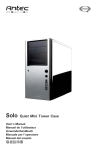
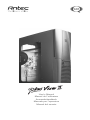
User’s Manual
Manuel de l’utilisateur
Anwenderhandbuch
Manuale per l’operatore
Manual del usuario
At Antec, we continually refine and improve our products to ensure the highest quality. So it's
possible that your new case may differ slightly from the descriptions in this manual. This isn't
a problem; it's simply an improvement. As of the date of publication, all features, descriptions,
and illustrations in this manual are correct.
Disclaimer
This manual is intended only as a guide for Antec's Computer Enclosures. For
more comprehensive instructions on installing your motherboard and peripherals,
please refer to the user's manuals which come with your components and drives.
PLUSVIEW II SOHO SERVER CASE WITH CLEAR SIDE WINDOW
This case comes with a clear side window. There is an 80mm fan mount with vents on the
window to cool the hottest graphics cards on the market. Your new case comes without a power
supply. We recommend installing Antec's TruePower 2.0 or NEO 480 power supply for best
performance.
SETTING UP
1. Place the case upright on a flat, stable surface. The 120mm exhaust fan should be at the back,
facing you.
2. Remove the thumb-screws from the right side panel. Unlatch the panel and remove it by
swinging it out. Note: Don't use your fingernail to pry or lift the panels.
3. Inside the case you should see some wiring with marked connectors (USB, PWR etc.), an
installed I/O panel, a tool box containing more hardware (screws, brass standoffs, plastic
stands, etc.), and eight drive rails.
INSTALLING THE POWER SUPPLY
1. With the case upright, place the power supply on the support beam that runs from the 5.25"
drive bays to the back of the case. Note: most dual-fan power supplies should be installed with
the second fan towards the bottom of the case.
2. Push the power supply to the back of the case and align the mounting holes.
3. Attach the power supply to the case, with the screws provided.
INSTALLING THE MOTHERBOARD
This manual does not cover CPU, RAM, or expansion card installation. Please consult your
motherboard manual for specific mounting instructions and troubleshooting.
1. Lay the case down, with the open side facing up. The drive cages and power supply should be visible.
2. Make sure you have the correct I/O panel for your motherboard. If the panel provided with
the case isn't suitable, please contact your motherboard manufacturer for the correct I/O panel.
3. Line up your motherboard with the standoff holes, and remember which holes are lined up.
Not all motherboards will match with all the provided holes; this is normal, and won't affect
functionality (in other words, there will likely be extra holes).
4. Remove your motherboard by lifting it up.
5. Screw the brass standoffs into the threaded holes that line up with your motherboard. Do not
overtighten the standoffs. Some standoffs may be pre-installed for your convenience.
6. Place your motherboard on the brass standoffs.
7. Screw in your motherboard to the standoffs with the provided Philips-head screws. Your
motherboard is now installed.
2
CONNECTING THE POWER AND LED
1. Connect the 24-pin or 20-pin ATX power connector and +12V 4-pin connector to your
motherboard. Note: an ATX12V v2.0 power supply comes with a 24-pin power connector.
This is the latest Intel form factor power supply.
2. Connect the Reset switch (labeled RESET SW) to your motherboard at the RST connector.
Make sure the label always faces the front of the case.
3. Power LED (labeled POWER LED) connector is located behind the Reset connector.
4. Power Switch (labeled POWER SW) connects to the PWR connector on the motherboard.
5. Speaker (labeled SPEAKER) connector is behind the PWR connector.
6. Hard Drive LED (labeled HDD) connects to the IDE connector.
7. LED I, LED II connectors: This case comes with two extra LEDs, marked I, II. You may use
these LED for various purposes such as SC SI LED, Message LED, etc.
CONNECTING THE USB PORTS
You will find a single 10-pin connector on a cable attached to the front USB ports. This is an Intel
standard connector, which is keyed so that it can't be accidently reversed as long as it is
connected to a proper Intel standard motherboard header. Connect the 10-pin connector to your
motherboard headers so that the blocked pin fits over the missing header pin.
Note: Please check your motherboard manual for your USB header pin layout and make sure it
matches the attached table. If it does not match this Intel standard, please call Antec customer
service at (800) 22ANTEC (North America) or +31 (0) 10 462-2060 (Europe) to buy a USB
adapter. This adapter will allow you to connect the front USB to your motherboard on a
pin-by-pin basis.
1
9
2
Motherboard Pin Layout
Pin
Signal Names
Pin
Signal Names
1
USB Power 1
2
USB Power 2
3
Negative Signal 1
4
Negative Signal 2
5
Positive Signal 1
6
Positive Signal 2
7
Ground 1
8
Ground 2
9
Key (No Pin)
10
Empty Pin
10
CONNECTING THE IEEE 1394 (FIREWIRE®, I.LINK®) PORT
You will find a single 10-pin connector on a cable attached to the front IEEE 1394 connection.
This is an Intel standard connector which is keyed so that it can't be accidentally reversed as long
as it is connected to a proper Intel standard motherboard header. Connect the 10-pin connector
to your motherboard header so that the blocked pin fits over the missing header pin.
Note: Please check your motherboard manual for your IEEE 1394 header pin layout and make
sure it matches the attached table. If you intend to connect the front FireWire port to an IEEE
1394 add-on card that comes with an external-type IEEE 1394 connector, please call Antec
customer service at (800) 22ANTEC (North America) or +31 (0) 10 462-2060 (Europe) to buy an
adapter. This adapter will allow you to connect the front IEEE 1394 port to the external-type
connector.
3
1
9
2
Motherboard Pin Layout for Front Panel IEEE 1394 Connector
Pin
Signal Names
Pin
Signal Names
1
TPA+
2
TPA–
3
Ground
4
Ground
5
TPB+
6
TPB–
7
+12V (Fused)
8
+12V (Fused)
9
Key (No Pin)
10
Ground
10
CONNECTING THE AUDIO PORTS
There is an Intel standard 10-pin connector (with 7 individual wires with connectors) coming out
from the front panel speaker and microphone connection If your motherboard supports Intel's
standard onboard audio connector, you can plug in the 10-pin connector directly onto the board.
For non-Intel standard audio connection, you need to plug the 7 individual connectors to the
motherboard. See instructions below:
Locate the internal audio connectors from your motherboard or sound card. Consult your
motherboard or sound card manual for the pin-out positions.
1.
2.
3.
4.
5.
6.
7.
Microphone Signal Pin: Connect the MIC connector to this pin.
Microphone Power: Connect the MIC-BIAS connector to this pin.
Ground Pin: Connect the GND connector to this pin.
Front Right Speaker Out Pin: Connect the FPOUT-R connector to this pin.
Front Left Speaker Out Pin: Connect to the FPOUT-L connector to this pin.
Rear Right Speaker Out Pin: Connect to the RET-R connector to this pin.
Rear Left Speaker Out Pin: Connect the RET-L connector to this pin.
Note: Your motherboard may not support rear speaker output. In this case, you do not need
to connect RET-R and RET-L.
3.5" DEVICE INSTALLATION
With the front bezel facing you, swing the plastic door out. It can open 270 degrees to rest against
the side of the case. You can see there are four 5.25" and two 3.5" external drive bays. Inside the
case there are two 3.5" drive cages that house six 3.5" drive bays of which two are for external 3.5"
devices and four are for internal 3.5" devices.
1. Pull the quick release lever towards the rear of the case and release the top cage first. Looking
from the rear of the case you can see some metal grills over the exposed (external) drive bays.
Carefully put a screwdriver through the metal grill and gently push the plastic drive bay cover
until it comes off. Carefully use your hands to twist the metal plate back and forth until it
breaks off.
Note: Don't remove the covers and plates for the drive bays that you are not using now. Be
careful of the newly exposed metal where the grills were attached, as these areas are likely to
be sharp.
2. Install your floppy drive into the top 3.5" drive bay.
3. Mount your other 3.5" device into the drive cage.
4. Slide and lock the drive cage back into the case.
5. Release the second cage.
Note: Inside the cage you will find a fan bracket. If you want to have a cooling fan in the drive
cage, you should install the fan before installing the drives. For fan installation please see the
Fan installation section of this manual.
4
6. Mount your other 3.5" devices into the drive cage.
7. Slide and lock the drive cage back into the case.
8. Find the proper connector on the power supply (SATA, floppy, or standard 4-pin) and
connect it to the male connector on your device.
5.25" DEVICE INSTALLATION
1. Take off the plastic drive bay covers and metal plates as described above.
2. Take two of the drive rails and mount them to the sides of the 5.25" device. Make sure the
metal portion is angled away from the device and facing forward.
3. Slide the device into the drive bay until you hear the rails click.
4. Mount the other devices accordingly. Connect the proper connector (SATA or standard 4-pin)
from the power supply to the male connector on the device.
THE COOLING SYSTEM
The TriCool Fan
The case includes one 120mm Blue LED TriCool fan installed in the rear. This fan comes with a
three-speed switch that lets you balance quiet performance with maximum cooling
(See specifications below). The fan is installed so that the air is blowing out of the case. Connect
a large 4-pin connector from the power supply to the male 4-pin connector on the fan.
Note: The minimum voltage to start the fan is 5V. We recommend setting the fan speed to High
if you choose to connect the fan to a fan control device or to the Fan-Only connector from an
Antec TruePower supply. A fan control device regulates fan speed by varying the voltage to it,
and the voltage may start as low as 4.5 V to 5V. Setting the TriCool speed to Medium or Low and
connecting it to a fan control device may result in the fan not being able to start as the already low
voltage from the fan control device will be further reduced by the TriCool circuitry to lower than 5V.
Specifications
Size:
Rated Voltage:
Operating Voltage:
120 x 120 x 25.4 mm
DC 12V
10.2V~13.8V
Speed
Input
Current
Air Flow
Static
Pressure
Acoustical
Noise
Input
Power
High
2000 RPM
0.24A
(Max.)
2.24 m³/min.
(79 CFM)
2.54 mm-H2O
(0.10 inch-H2O)
30 dBA
2.88 W
Medium
1600 RPM
0.2A
1.59m³/min.
(56 CFM)
1.53 mm-H2O
(0.06 inch-H2O)
28 dBA
2.4 W
Low
1200 RPM
0.13A
1.1 m³/min.
(39 CFM)
0.92 mm-H2O
(0.04 inch-H2O)
25 dBA
1.56 W
This case comes with two 80mm front fan mounts and one 80mm side fan mount should you
choose to install additional cooling fans.
Front 80mm fan mounts
There are two plastic fan cages. One of them is located inside the 3.5" drive cage to cool your hard
drives directly. You should install this fan before you mount your HDD drives into the cage. Install
both front-mounted fans by dropping the fan to the cage and pushing it in until it snaps in place.
These fans must be installed so that the air is blowing into the case. We recommend using Antec
80mm TriCool fans to balance quiet performance with maximum cooling. (See our website for
more product information.) Note: Please choose your fan speed wisely. In most cases, a
medium or even low speed setting will be enough to supply adequate cooling.
5
VGA Card Cooling
There is an 80mm fan mount with vents on the clear side window right above the VGA card. The
vents can supply fresh air to the card without a fan (passive cooling), or with a fan (active cooling)
if you are using a high performance VGA card that needs extra cooling. Install the fan so that the
air is blowing into the case. We recommend using an Antec 80mm TriCool fan.
Maintaining the Washable Air Filter
From time to time it will be necessary to wash the installed air filter. Not washing the air filter will
result in higher system temperatures and possible stability problems. We recommend checking the
air filter at least once a month initially. The frequency will change depending on system usage
(users whose systems run 24/7 will likely have to check/wash more often than those who don't
use their systems every day) and on environmental conditions.
6
Antec, Inc.
47900 Fremont Blvd.
Fremont, CA 94538
Tel: 510-770-1200
Fax: 510-770-1288
Antec Europe B.V.
Sydneystraat 33
3047 BP Rotterdam
The Netherlands
Tel: +31 (0) 10 462-2060
Fax: +31 (0) 10 437-1752
Technical Support
US & Canada
1-800-22ANTEC
[email protected]
Europe
+31 (0) 10 462-2060
[email protected]
www.antec.com
© Copyright 2005 Antec, Inc. All rights reserved. All trademarks are the property of their respective owners.
Reproduction in whole or in part without written permission is prohibited. Printed in China.
Version 1.0.1 6/01/2005