1
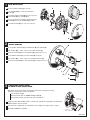
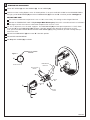
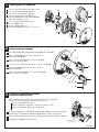
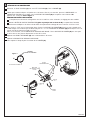
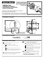
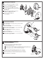
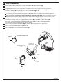
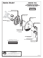
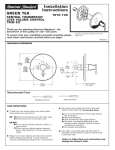
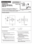
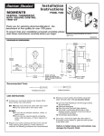
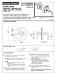
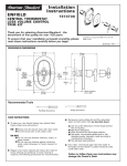
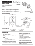
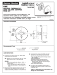
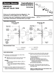
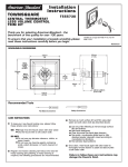
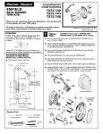
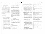
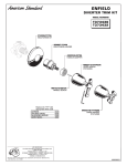
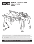
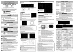
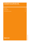
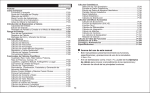
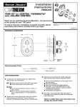
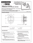
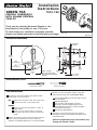
Installation
Instructions
GREEN TEA
T010.740
CENTRAL THERMOSTAT
WITH VOLUME CONTROL
TRIM KIT
Thank you for selecting American-Standard...the
benchmark of fine quality for over 100 years.
To ensure that your installation proceeds smoothly
please read these instructions carefully before you begin.
Certified to comply with ANSI A112.18.1M
ASSE 1016
M968022
ROUGHING-IN DIMENSIONS
FINISHED
WALL
200mm
(7-7/8)
100mm
(3-7/8)
186mm
(7-3/8)
R520
1/2" NPT INLETS
or
R540
3/4" NPT INLETS
150mm
(6)
25mm
NOTE: FITTING
(1)
MUST BE INSTALLED
WITH VOLUME CONTROL
ON TOP.
48mm to 68mm
(2 to 2-5/8)
Recommended Tools
Flat Blade Screwdriver
Phillips Screwdriver
CARE INSTRUCTIONS:
To keep your new faucet looking new, please follow
these simple care instructions:
DO:
Simply rinse the faucet clean with clear water.
Dry the faucet with a soft cotton cloth.
DO NOT:
Do not use any abrasive cleaners, cloths, or
paper towels.
Do not use any cleaning agents containing
acids, polish abrasives, or harsh cleaners or
soaps.
Regular and routine cleaning will reduce the need for
heavy cleaning and polishing. If heavy cleaning is
required, the following procedures are recommended:
Remove as much surface dirt and film using clear
water and soft cotton cloth (as described above).
Use any of the following to remove tough surface
film and build-up:
Mild liquid detergents
Clear ammonia free liquid glass cleaners
Non-acidic, non-abrasive gentle liquid or fully
dissolved powder cleansers mixed according to
manufacturers directions.
Non-abrasive liquid polishers
Once clean, rinse faucet again with clear water to
thoroughly remove cleaner or polish and blot dry with
a soft cotton cloth.
Failure to follow these care instructions may
damage the Faucet's finish.
1
TRIM INSTALLATION
2
Remove PLASTER GUARD (1) if attached.
Push CAPS (2 & 2a) as shown onto CONTROL
VALVES (3).
Push ESCUTCHEON HOLDER (4) with lightly greased
O-RING SEALS (5) over CAPS (2, 2a).
TOP
4
1
3
Attach the FIXATION PLATE (7) to the ESCUTCHEON
HOLDER (4) with the two SCREWS (6) provided.
Push ESCUTCHEON (8) flush against finished wall.
2a
6
5
7
8
1
2
INSTALL HANDLES
8
Attach HANDLE ADAPTER (1) to KNOB MOUNT (2) with SCREW (3).
Align HANDLE (4) as shown and push onto KNOB MOUNT (2).
7
Tighten SET SCREW (5) with HEX WRENCH (6) supplied with trim kit.
Install HANDLE SCREW (7) into VALVE STEM (8) and tighten.
Align HANDLE (9) as shown and push onto HANDLE SCREW (7).
9
Tighten SET SCREW (5a) with HEX WRENCH (6) su pplied with trim kit.
5a
2
1
4
3
5
6
3
TRANSPOSED SUPPLY PIPING
OR BACK TO BACK INSTALLATION
Should the hot and cold water supply pipes have been transposed making
adjustment impossible, proceed as follows:
Shut off water supply.
Remove handle and rim. (Reverse steps 1 and 2).
Remove check stops and re-install them transposed.
CHECK STOP
(BLUE TO RED)
Important note: RED CHECK STOP is now on the right of the mixer body and the BLUE
CHECK STOP is now on the left.
Turn the water supply back on and perform the temperature adjustment in step 4.
Assemble HANDLES and TRIM.
CHECK STOP
(RED TO BLUE)
M968022
4
TEMPERATURE ADJUSTMENT
Loosen SET SCREW (1) with HEX WRENCH (2). Pull off HANDLE (3).
Check that arrow marking B points to the 12 o'clock position. If not, push the BLACK CLAMP on the SECURING RING to
the right, pull off KNOB MOUNT (4) and reinstall KNOB MOUNT (4) with arrow "B" 12 o'clock position. See Figure 1.
SET HOT LIMIT STOP
The maximum mixed water temperature is set at 109˚F at the factory. This setting can be changed if desired.
Remove the TEMPERATURE LIMIT STOP (H shaped Black Plastic part). Reinstall it at the desired notch as indicated in
the diagram to limit the maximum mixed water temperature to 104˚F or 112˚F.
For 100 F adjustment, turn the water supply on. Turn KNOB MOUNT (4) until the spout temperature is 100˚F. Check
that arrow "A" on the KNOB MOUNT (4) still points 12 o'clock position after adjusting the thermostat to 100˚F.
If not, pull out the RED LOCKING DEVICE. Remove KNOB MOUNT (4) by pulling it towards you while standing directly in
front of the valve.
Reinstall the KNOB MOUNT (4) with arrow "A" 12 o'clock position.
Reinstall RED LOCKING DEVICE.
See Step 2 for HANDLE (3) installation.
ARROWS AT 12 O'CLOCK
POSITION
Figure 1
4
TEMPERATURE
LIMIT STOP
KNOB MOUNT
RED LOCKING
DEVICE
112
109
4
104
ARROW
"B"
ARROW
"A"
3
1
BLACK
CLAMP
2
M968022
GREEN TEA
CENTRAL THERMOSTAT
WITH VOLUME CONTROL
TRIM KIT
MODEL NUMBER
T010.740
M962630-0070A
ESCUTCHEON HOLDER
A924335-0070A
FIXATION PLATE
M907712-YYY0A
ESCUTCHEON
A907090-YYY0A
CAP
M918318-0070A
HANDLE SCREW
023774-0070A
SCREWS
Replace the "YYY" with
appropriate finish code
CHROME
SATIN NICKEL
STAINLESS STEEL
002
295
075
M918038-0070A
ADAPTER
M918990-0070A
SELF TAPPING SCREW
M962731-YYY0A
HANDLE KIT
HOT LINE FOR HELP
For toll-free information and answers to your questions, call:
1-800-442-1902
Weekdays 8:00 a.m. to 6:00 p.m. EST
IN CANADA 1-800-387-0369 (TORONTO 1-905-306-1093)
Weekdays 8:00 a.m. to 7:00 p.m. EST
IN MEXICO 01-800-839-12-00
Product names listed herein are trademarks of American Standard Inc.
© AS America, Inc. 2008
M968022
Installation
Directives
GREEN TEA
T010.740
THERMOSTAT CENTRAL
AVEC RÉGLAGE DE DÉBIT
JEU DE GARNITURE
Nous vous remercions d'avoir choisi American Standard…
synonyme de qualité supérieure depuis plus de 100 ans.
Pour que l’installation se déroule sans problème,
veuillez lire attentivement ces instructions avant
de commencer.
Certifié conforme aux normes ANSI A112.18.1M
ASSE 1016
M968022
MESURES RELATIVES AUX POINTS DE RACCORDEMENT
MUR
FINI
200 mm
(7 7/8)
100 mm
(3 7/8)
186 mm
(7 3/8)
R520
ENTRÉES ½ po NPT
ou
R540
ENTRÉES ¾ po NPT
150 mm
(6)
REMARQUE : LE
RACCORDEMENT
DOIT ÊTRE POSÉ
AVEC LE RÉGLAGE
DE DÉBIT SUR LE
DESSUS.
25 mm
(1)
48 mm à 68 mm
(2 à 2 5/8)
Outils recommandés
Tournevis à lame plate
INSTRUCTIONS D’ENTRETIEN :
Pour conserver l’aspect de neuf de votre robinet, suivez ces
simples instructions d’entretien :
À FAIRE :
Simplement rincer le robinet avec de l’eau
propre.
Essuyer le robinet avec un chiffon de
coton doux.
À NE PAS FAIRE :
Ne pas utiliser de produits de nettoyage
abrasifs, du tissu ou des papiers de
ménage.
Ne pas utiliser de produits de nettoyage qui
contiennent de l’acide, des agents de polissage
abrasif, des nettoyants ou des savons rudes.
Un entretien régulier et routinier diminuera le besoin d’un
nettoyage intense et du polissage. En cas de nettoyage intense,
suivre les procédures recommandées.
Tournevis Phillips
Enlever autant que possible les saletés et le film à l’aide d’eau
claire et d’un chiffon de coton doux (tel que décrit ci-dessus).
Utiliser l’un des suivants pour enlever les films et les
accumulations tenaces :
Détergents liquides doux
Produits de nettoyage pour vitres sans ammoniac
Des liquides doux non acides, non abrasifs ou des produits de
nettoyage en poudre bien dilués mélangés selon les instructions
du fabricant.
Des liquides polisseurs non abrasifs
Lorsqu'il est propre, nettoyer et rincer le robinet avec de l'eau
claire pour bien enlever le produit de nettoyage et éponger
avec un chiffon en coton doux.
Le défaut de suivre ces instructions d’entretien
peutentraîner la détérioration du robinet.
1
INSTALLATION DE LA GARNITURE
Enlever les PROTECTIONS DE PLÂTRE (1), si fixées.
2
Pousser les CAPUCHONS (2 et 2a) comme
illustré sur les VANNES DE RÉGLAGE (3).
Pousser le SUPPORT DE ROSACE (4) sur les
CAPUCHONS (2 et 2a) les JOINTS TORIQUES (5)
doivent être légèrement graissés.
TOP
4
1
3
Fixer la PLAQUE DE FIXATION (7) à l’aide
des deux VIS (6) fournies.
Pousser la ROSACE (8) sur les
CAPUCHONS (2, 2a) et appuyer à ras du mur fini.
2a
5
7
6
8
1
2
INSTALLATION DES POIGNÉES
8
Fixer l’ADAPTATEUR (1) AU SUPPORT DE POIGNÉE (2) AVEC LES VIS (3).
Aligner la POIGNÉE (4) comme illustré et pousser dans le
SUPPORT DE POIGNÉE (2).
7
Serrer la VIS DE FIXATION (5) avec la CLÉ À SIX PANS (6)
fournie avec le jeu de garniture.
Installer et visser la VIS DE POIGNÉE (7) sur la TIGE de la VANNE (8).
9
Aligner la POIGNÉE (9) comme illustré et pousser dans la
VIS DE POIGNÉE (7).
5a
Serrer la VIS DE FIXATION (5a) avec la CLÉ À SIX PANS (6)
fournie avec le jeu de garniture.
2
1
4
3
5
6
3
CONDUITE D’ALIMENTATION INVERSÉE
OU INSTALLATION DOS À DOS
Si les conduites d’alimentation d’eau chaude et froide ont été inversées
rendant l’ajustement inpossible, procéder comme suit :
Fermer le robinet d'alimentation.
Retirer la poignée et la bordure. (Inverser les étapes 1 et 2).
Retirer les butées de vérification et les inverser.
BUTÉE DE VÉRIFICATION
(BLEU À ROUGE)
Remarque importante : La BUTÉE DE VÉRIFICATION ROUGE est maintenant à droite
du mélangeur et la BUTÉE DE VÉRIFICATION BLEUE est maintenant à gauche.
Rouvrir l’alimentation d’eau et exécuter l'ajustement de température décrit à l’étape 4.
Assembler les POIGNÉES et la garniture.
BUTÉE DE VÉRIFICATION
(ROUGE À BLEU)
M968022
4
RÉGLAGE DE LA TEMPÉRATURE
Desserrer la VIS DE FIXATION (1) avec une CLÉ À SIX PANS (2). Tirer la POIGNÉE (3).
Vérifier que la flèche indiquant un B pointe vers 12 heures. Dans le cas contraire, pousser la BRIDE NOIRE sur
l’ANNEAU DE FIXATION vers la droite, tirer le SUPPORT DE POIGNÉE (4) et le reposer avec la flèche « B »
pointant vers 12 heures. Voir la figure 1.
RÉGLAGE DE BUTÉE D'EAU CHAUDE
La température maximale du mélange d’eau est fixé à 109°F en usine. Au besoin, ce réglage peut être modifié.
Retirer la BUTÉE DE LIMITE DE TEMPÉRATURE (pièce en plastique noir en forme de H). La reposer dans l’encoche
voulue comme indiqué sur le schéma afin de limiter la température du mélange de l'eau à maximum 104°F ou 112°F.
Pour ajuster à 100°F, ouvrir l’alimentation d’eau. Tourner le SUPPORT DE POIGNÉE (4) jusqu’à ce que la température
au bec indique 100°F. Vérifier que la flèche indiquant un « A » sur le SUPPORT DE POIGNÉE (4) pointe toujours vers 12
heures une fois le thermostat réglé sur 100°F.
Dans le cas contraire, tirer le DISPOSITIF DE VERROUILLAGE ROUGE. Tirer le SUPPORT DE POIGNÉE (4) vers vous pour
le sortir tout en vous plaçant directement en face de la vanne.
Reposer le SUPPORT DE POIGNÉE (4) avec la flèche « A » à 12 heures.
Reposer le DISPOSITIF DE VERROUILLAGE ROUGE.
Vous reporter à l’étape 2 pour l’instalation de la POIGNÉE (3).
POSITION
FLÈCHES À 12 HEURES
Figure 1
4
BUTÉE
DE TEMPÉRATURE
SUPPORT DE POIGNÉE
DISPOSITIF
DE VERROUILLAGE
ROUGE
112
109
4
104
FLÈCHE
«B»
FLÈCHE
«A»
3
1
BRIDE
NOIRE
2
M968022
GREEN TEA
THERMOSTAT CENTRAL
AVEC RÉGLAGE DE DÉBIT
JEU DE GARNITURE
NUMÉRO DU MODÈLE
T010.740
M962630-0070A
SUPPORT DE ROSACE
A924335-0070A
PLAQUE DE FIXATION
M907712-YYY0A
ROSACE
A907090-YYY0A
CAPUCHON
M918318-0070A
VIS DE LA POIGNÉE
023774-YYY0A
VIS DU SUPPORT À ROSACE
Remplacer les « YYY » par
Code approprié du fini
CHROME
NICKEL SATINÉ
ACIER INOXYDABLE
002
295
075
M918038-0070A
ADAPTATEUR
M918990-0070A
VIS À AUTO-FILETAGE
M962731-YYY0A
TROUSSE DE
LA POIGNÉE
LIGNE D’URGENCE
Pour obtenir des renseignements ou une réponse
à vos questions, composez sans frais le :
1-800-442-1902
Jours de la semaine 8 h à 18 h HNE
AU CANADA 1-800-387-0369 (TORONTO 1-905-306-1093)
Jours de la semaine 8 h à 19 h HNE
AU MEXIQUE 01-800-839-12-00
Les noms des produits nommés ci-après sont des marques de commerce
déposées d’American Standard Inc. © AS America, Inc. 2008
M968022
Instrucciones
de Instalación
GREEN TEA
T010.740
TERMOSTATO CENTRAL
CON CONTROL DE VOLUMEN
JUEGO DE MOLDURA
Gracias por elegir American Standard, el referente
de calidad por más de 100 años.
Para asegurarse de realizar la instalación sin inconvenientes,
lea cuidadosamente estas instrucciones antes de comenzar.
Cumplimiento certificado de la norma ANSI A112.18.1M
ASSE 1016
M968022
DIMENSIONES DE INSTALACIÓN
PARED
TERMINADA
200mm
(7-7/8)
100mm
(3-7/8)
186mm
(7-3/8)
R520
Entradas de 1/2" NPT
o
R540
Entradas de 3/4" NPT
150mm
(6)
25mm
NOTA: LOS ACCESORIOS
(1)
DEBEN INSTALARSE CON
EL CONTROL DE VOLUMEN
EN LA PARTE SUPERIOR.
48mm a 68mm
(2 a 2-5/8)
Herramientas recomendadas
Destornillador de punta plana
Destornillador Phillips
INSTRUCCIONES PARA EL CUIDADO:
Para mantener su grifo como nuevo, siga estas simples
instrucciones de cuidado:
DEBE:
Lavar el grifo solo con agua limpia.
Secar el grifo con un paño suave de algodón.
NO DEBE:
Utilizar limpiadores o paños abrasivos ni toallas de
papel.
Utilizar ningún agente de limpieza que contenga ácidos,
pasta abrasiva ni limpiadores o jabones duros.
La limpieza regular y rutinaria hará menos necesario limpiar y
pulir en forma profunda.Si se requiere una limpieza profunda,
recomendamos los siguientes procedimientos:
Quite cuanta suciedad pueda con agua limpia y un paño de
algodón suave (como se señaló anteriormente).
Use cualquiera de los siguientes elementos para quitar los
residuos y acumulaciones resistentes de la superficie:
Detergentes líquidos suaves.
Limpiadores de vidrio líquidos transparentes sin amoníaco.
Limpiadores suaves, no abrasivos, no ácidos, líquidos o
en polvo completamente disueltos, mezclados según las
instrucciones del fabricante.
Pulidores líquidos no abrasivos.
Una vez limpio, enjuague nuevamente el grifo con agua limpia
para quitar a fondo los restos del limpiador o pasta y séquelo
con un paño de algodón.
Si no sigue estas instrucciones para el cuidado
puede dañar el acabado del grifo.
1
INSTALACIÓN DE LA MOLDURA
Retire el PROTECTOR DE YESO (1) si se incluye.
2
Presione las TAPAS (2 & 2a) como se muestra
sobre las VÁLVULAS DE CONTROL (3).
Coloar la base de la placa (4) con los empaques
de anillo O-ring (5) ligeramente enqrasados sobre
las (2, 2a) tapas.
TOP
4
1
3
Acoplav la base de fijación (7) con la base de la
placa (4) con los (6) tornillos incluidos.
Presione el CHAPETÓN (8) sobre
las TAPAS (2, 2a).
2a
6
5
7
8
1
2
INSTALACIÓN DE MANIJAS
8
Instale el ADAPTADOR DE MANIJA (1) al MONTAJE DE PERILLA (2)
con el TORNILLO (3).
Alinee la MANIJA (4) como se muestra y presiónela contra el
MONTAJE DE PERILLA (2).
7
Apriete el TORNILLO DE AJUSTE (5) con la LLAVE HEXAGONAL (6)
suministrada con el juego de molduras.
Instale el TORNILLO DE LA MANIJA (7) en el VÁSTAGO DE
LA VÁLVULA (8) y apriete.
9
5a
Alinee la MANIJA (9) como se muestra y presiónela contra el
TORNILLO DE LA MANIJA (7).
Apriete el TORNILLO DE AJUSTE (5a) con la LLAVE HEXAGONAL (6)
suministrada con el juego de molduras.
2
1
4
3
5
6
3
TUBERÍA DE SUMINISTRO TRANSPUESTA
O INSTALACIÓN RECÍPROCA
Si las tuberías de suministro de agua caliente y fría se han
transpuesto imposibilitando el ajuste, realice lo siguiente:
Cierre el suministro de agua.
Retire la manija y la moldura. (Haga el procedimiento inverso de los pasos 1 y 2).
Saque los topes de control y vuelva a instalarlos transpuestos.
TOPE DE CONTROL
(AZUL A ROJO)
Nota importante:El TOPE DE CONTROL ROJO ahora está a la derecha
del cuerpo mezclador y el TOPE DE CONTROL AZUL está a la izquierda.
Abra el suministro de agua y realice el ajuste de temperatura del paso 4.
Monte las MANIJAS y las MOLDURAS.
TOPE DE CONTROL
(ROJO A AZUL)
M968022
4
AJUSTE DE TEMPERATURA
Afloje el TORNILLO DE AJUSTE (1) con la LLAVE HEXAGONAL (2).Saque la MANIJA (3).
Compruebe que la flecha con la marca B apunte a la posición de las 12 en punto.Si no lo hace, presione la
GRAPA NEGRA del ANILLO DE SEGURIDAD hacia la derecha, saque el MONTAJE DE PERILLA (4) y vuelva a
instalarlo con la flecha "B" en la posición de las 12 en punto.Vea la Figura 1.
AJUSTE EL LIMITADOR DE AGUA CALIENTE
La temperatura de agua mezclada máxima está establecida de fábrica en 109˚F.Este ajuste puede modificarse.
Saque el LIMITADOR DE TEMPERATURA (la parte plástica negra con forma de H).Vuelva a instalarlo en la muesca
deseada como se indica en el diagrama para limitar la temperatura de agua mezclada máxima a 104˚F o 112˚F.
Para el ajuste de 100˚F (38 ˚C), abra el suministro del agua.Gire el MONTAJE DE PERILLA (4) hasta que
la temperatura del pico sea de 100˚F. Compruebe que la flecha “A” en el MONTAJE DE LA PERILLA (4)
apunta a posición de las 12 en punto luego de ajustar el termostato a 100˚F.
Si no lo hace, saque el DISPOSITIVO DE BLOQUEO ROJO.Quite el MONTAJE DE LA PERILLA (4) jalándola
hacia usted mientras permanece de pie justo frente a la válvula.
Vuelva a instalar el MONTAJE DE PERILLA (4) con la flecha "A" en la posición de las 12 en punto.
Vuelva a instalar el DISPOSITIVO DE BLOQUEO ROJO.
Consulte el paso 2 para la instalación de la MANIJA (3).
LAS FLECHAS PUESTAS A LAS
12 EN PUNTO
Figura 1
4
LIMITADOR DE
TEMPERATURA
MONTAJE DE PERILLA
DISPOSITIVO DE BLOQUEO
ROJO
112
109
4
104
FLECHA
"B"
FLECHA
"A"
3
1
GRAPA
NEGRA
2
M968022
GREEN TEA
TERMOSTATO CENTRAL
CON CONTROL DE VOLUMEN
JUEGO DE MOLDURA
NÚMERO DE MODELO
T010.740
M962630-0070A
SUJETADOR DEL CHAPETÓN
A924335-0070A
FIXATION PLATE
M907712-YYY0A
CHAPETÓN
A907090-YYY0A
TAPA
M918318-0070A
TORNILLO DE MANIJA
023774-YYY0A
TORNILLOS DEL
SUJETADOR DEL
CHAPETÓN
M918038-0070A
ADAPTADOR
Reemplace las "YYY" con
el código de acabado correspondiente.
CROMO
NÍQUEL SATINADO
ACERO INOXIDABLE
002
295
075
M918990-0070A
TORNILLO AUTOROSCANTE
M962731-YYY0A
JUEGO DE MANIJA
ASISTENCIA TELEFÓNICA
Llame sin costo para obtener información y respuestas a sus preguntas:
1-800-442-1902
De lunes a viernes de 8:00 a.m. a 6:00 p.m. hora del este de EE.UU.
EN CANADÁ 1-800-387-0369 (TORONTO 1-905-306-1093)
De lunes a viernes de 8:00 a.m. a 7:00 p.m. hora del este de EE.UU.
EN MÉXICO 01-800-839-12-00
Los nombres de productos que aparecen en este documento son marcas
comerciales de American Standard Inc. © AS America, Inc. 2008
M968022