1
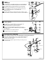
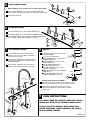
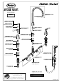
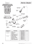
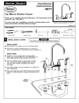
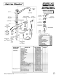
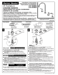
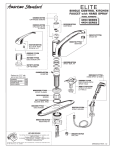
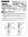
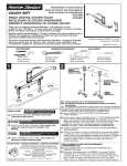
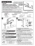
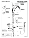
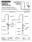
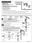
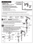
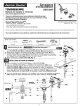
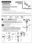
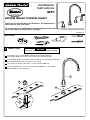
Installation
Instructions
THE
COLLECTION
4251
™
by
BOTTOM MOUNT KITCHEN FAUCET
Thank you for selecting American-Standard...the benchmark of
fine quality for over 100 years.
To ensure that your installation proceeds smoothly--please read
these instructions carefully before you begin.
Certified to comply with ASME A112.18.1M
M968412A
TOOLS REQUIRED
Flat Blade Screwdriver
Adjustable Wrench
Plumbers' Putty or Caulking
Phillips Screwdriver
Tubing Cutter
Channel Locks
1
INSTALL FAUCET
CAUTION
Turn off hot and cold water supplies before beginning.
Install LOCK NUT (1) and RUBBER WASHER (2) onto SPOUT BODY (3).
Insert SPOUT BODY (3) through mounting hole from underside of SINK.
Place RUBBER RING (4) into SPOUT ESCUTCHEON (5) and thread ESCUTCHEON (5)
onto SPOUT BODY (3) until snug against internal stop.
From under sink tighten LOCK NUT (1) to secure SPOUT BODY (3).
Make sure O-RING (6) is in place. Thread SPOUT ASSEMBLY (7) onto SPOUT
ESCUTCHEON (5) and hand tighten.
7
5
6
4
3
2
1
2
INSTALL
VALVE BODIES
5
Install LOCK NUT (1) and RUBBER WASHER (2) onto VALVE BODIES (3).
Insert VALVE BODY (3) through mounting hole from underside of SINK.
4
Place RUBBER RING (4) into DECK ADAPTER (5) and thread DECK
ADAPTER (5) onto VALVE BODY (3) until snug against internal stop.
2
Set VALVE BODIES (3), so that their outlets are facing toward center
of sink, and tighten LOCK NUT (1) using WRENCH (8)
supplied with faucet.
3
Insert SEAL WASHERS (6) into SPOUT BODY SUPPLY HOSES (7). Loop
SUPPLY HOSES (7) if required and tighten connection to VALVE BODIES (3).
7
1
6
8
3
6
INSTALL HANDLES
5
Push ADAPTER (1) on VALVE STEM (2), so that the hole of the
ADAPTER (1) without spline is facing up. See figure "A".
Thread HANDLE BASE (3) onto DECK ADAPTER (7)
4
TOP
Find correct position of HANDLE (4) by adjusting male teeth on
ADAPTER (1) to female teeth in HANDLE (4) and push HANDLE (4)
onto ADAPTER (1).
Secure HANDLE (4) with HANDLE SCREW (5).
3
1
Figure "A"
2
Push INDEX CAP (6) in hole of HANDLE (4).
7
SPLINE END DOWN
4
MAKE WATER SUPPLY CONNECTIONS
NOTE: FLEXIBLE SUPPLIES OR BULL-NOSE RISERS MUST BE PURCHASED SEPARATELY.
Connect water supply to FAUCET (1) with 1/2" IPS FLEXIBLE SUPPLIES (3)
or 3/8"O.D. BULL-NOSE RISERS (2). Use adjustable wrench to tighten
connections. Do not over tighten.
Be careful not to kink copper supply when bending. Use tubing cutter to
cut to proper length.
1
COUPLING NUT
2
3
FERRULE
M968412A
5
INSTALL SPRAY HOLDER
NOTE: FAUCET can be installed with or without Hand Spray.
1
Place SPRAY HOLDER (1) into separate hole of SINK (2)
and assemble NUT (3) onto shank from underside of SINK (2).
Hand tighten NUT (3).
2
3
6
FITTING WITH SPRAY
Unscrew SPRAY CAP (5) from HOSE ADAPTOR (4).
Feed SPRAY HOSE (1) through SPRAY HOLDER (2) and
attach COUPLING NUT (3) of HOSE (1) to HOSE ADAPTOR (4)
on valve body. Tighten COUPLING NUT (3) firmly.
4
1
5
2
3
7
TEST INSTALLED FAUCET
8
SERVICE
1
2
To change direction of handle rotation,
proceed as follows:
Turn valve to OFF position.
Pull out INDEX CAP (1) and remove
HANDLE SCREW (2).
Pull off HANDLE (3), and unscrew
ESCUTCHEON (4).
Pull off STEM ADAPTER (7).
Remove SPRING CLIP (6).
Lift STOP WASHER (5), turn 90
degrees and replace.
Replace SPRING CLIP (6) and STEM
ADAPTER (7).
Reinstall ESCUTCHEON (4) and
HANDLE ASSEMBLY (1,2 & 3).
Remove AERATOR. With handles in OFF
position, turn on water supplies and check
all connections for leaks.
Operate both HANDLES to flush water lines
thoroughly. Rotate SPOUT in both directions.
Replace AERATOR.
Direct SPRAY HEAD into sink and activate
SPRAY. Check HOSE connections for leaks.
3
4
7
90
5
6
AERATO
If faucet drips proceed as follows:
Aerator may accumulate dirt causing distorted and
reduced water flow. Remove aerator and rinse clean.
If spout drips, operate handles several times
from OFF to ON position. Do not force - handles
turn only 90 .
9
CARE INSTRUCTIONS:
DO: SIMPLY RINSE THE PRODUCT CLEAN WITH CLEAR
WATER. DRY WITH A SOFT COTTON FLANNEL CLOTH.
DO NOT: CLEAN THE PRODUCT WITH SOAPS, ACID,
POLISH, ABRASIVES, HARSH CLEANERS, OR A CLOTH
WITH A COARSE SURFACE.
M968412A
THE
“
”
COLLECTION
™
by
BOTTOM MOUNT
KITCHEN FAUCET
MODEL NUMBER
M962265-YYY0A
SPOUT KIT
4251
066070-YYY0A
AERATOR
M962162-0070A
INDEX BUTTON (HOT)
M962163-0070A
INDEX BUTTON (COLD)
918428-0070A
HANDLE SCREW
923012-0070A
CLIP
M962165-YYY0A
LEVER HANDLE
073542-0070A
SPOUT O-RING
M962267-YYY0A
SPOUT ESCUTCHEON
M908505-YYY0A
HANDLE ESCUTCHEON
918049-0070A
HANDLE ADAPTER
M961634-0070A
SPOUT MOUNTING KIT
A952026-0070A
DIVERTER
M962161-0070A
DECK ADAPTER KIT
994053-0070A
CARTRIDGE
M953667-YYY0A
HANDSPRAY & HOSE
M961634-0070A
VALVE MOUNTING KIT
060341-0070A
SPRAY CAP
M953040-YYY0A
SPRAY HOLDER
M961635-0070A
TUBE & SEAL KIT
024220-0070A
SUPPLY NUT
Replace the "YYY" with
appropriate finish code
HOT LINE FOR HELP
For toll-free information and answers to your questions, call:
1-800 442-1902
Weekdays 8:00 a.m. to 8:00 p.m. EST
CHROME
SATIN
002
295
IN CANADA 1-800-387-0369 (TORONTO 1-905-306-1093)
Weekdays 8:00 a.m. to 7:00 p.m. EST
Product names listed herein are trademarks of American Standard Inc.
© American Standard Inc. 2003
M968412A