1
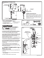
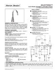
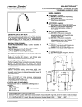
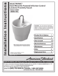
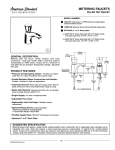
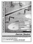
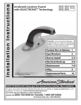
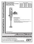
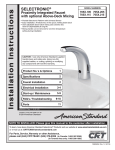
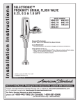
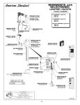
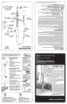
I n s t a l l a t i o n I n s t ru c t i o n s
SELECTRONIC®
Proximity Integrated Faucet
with Optional Above-Deck Mixing
• Flexible Selectronic® Platform with Universal Sensor
• Easy installation. All electronics in the spout; nothing below deck.
• User adjustable above-deck mixing uses ceramic disc
valve for dependability & long life
• Mixing handle can be removed for one time temperature
setting during installation
• Available in DC (Battery) & AC versions
Product No.'s & Options
1
Specifications
2
How to Install
2-3
Maintenance
3-7
FAQ,s
7-8
Replacement Parts
8
7055.105
7055.115
7056.105
7056.115
7055.205
7055.215
7056.205
7056.215
Certified to comply with ASME A112.18.1M
© 2012 American Standard
M 9 6 5 2 5 5 R E V. 1. 6
NOTE TO INSTALLER: Please give this manual to the customer after installation.
To learn more about American Standard Faucets visit our website at: www.americanstandard-us.com
or U.S. customer's e-mail us at: [email protected]
For Parts, Service, Warranty or other Assistance,
please call 1-800-442-1902 (In Canada: 1-800-387-0369)
(In Toronto Area only: 1-905-3061093)
Thank you for selecting American-Standard...the benchmark of fine quality for over 100 years.To ensure
that your installation proceeds smoothly--please read these instructions carefully before you begin.
UNPACKING
All American Standard Faucets Are Water Tested At Our Factory.
Some Residual Water May Remain In The Faucet During Shipping.
1. Remove the fitting and loose items from the carton. The illustration below shows the fitting and all loose items
after they have been removed from the carton. Some items may be packaged partially assembled to other items.
1. Selectronic Spout Assembly
2. Mounting Kit
3. Battery (7055 Series)
3a. AC Power Supply (7056 Series)
4. 4" Deck plate (optional must be ordered separately)
5. Mixing Valve (optional must be ordered separately)
6. Key for vandal resistant aerator
7. Installation Instructions
8. Hose Adapters
Less Mixing
With Above-Deck Mixing
PRODUCT No.s
7055.105
7055.115
PRODUCT No.s
7055.205
7055.215
7056.105
7056.115
7056.205
7056.215
6
6
B
DO NOT REMOVE
PROTECTIVE FILM
FROM SENSOR EYE
UNTIL INSTALLATION
IS COMPLETE.
a
DO NOT REMOVE
PROTECTIVE FILM
FROM SENSOR EYE
UNTIL INSTALLATION
IS COMPLETE.
s
e
3
3
1
1
P r o
d
with Optional Above-Deck Mixing
• Flexible Selectronic® Platform with Universal Sensor
• Easy installation. All electronics in the spout; nothing below deck.
• User adjustable above-deck mixing uses ceramic disc
valve for dependability & long life
• Mixing handle can be removed for one time temperature
setting during installation
• Available in DC (Battery) & AC versions
t
Product No.'s & Options
1
Specifications
2
How to Install
2-3
Maintenance
3-7
FAQ,s
7-8
Replacement Parts
8
7055.105
7055.115
7056.105
7056.115
I n s t a l l a t i o n I n s t ru c t i o n s
c
I n s t a l l a t i o n I n s t ru c t i o n s
u
SELECTRONIC®
Proximity Integrated Faucet
7055.205
7055.215
7056.205
7056.215
3a
7
8
Certified to comply with ASME A112.18.1M
© 2012 American Standard
M 9 6 5 2 5 5 R E V. 1. 6
NOTE TO INSTALLER: Please give this manual to the customer after installation.
To learn more about American Standard Faucets visit our website at: www.americanstandard-us.com
or U.S. customer's e-mail us at: [email protected]
For Parts, Service, Warranty or other Assistance,
please call 1-800-442-1902 (In Canada: 1-800-387-0369)
(In Toronto Area only: 1-905-3061093)
705P400
2
SELECTRONIC®
Proximity Integrated Faucet
with Optional Above-Deck Mixing
• Flexible Selectronic® Platform with Universal Sensor
• Easy installation. All electronics in the spout; nothing below deck.
• User adjustable above-deck mixing uses ceramic disc
valve for dependability & long life
• Mixing handle can be removed for one time temperature
setting during installation
• Available in DC (Battery) & AC versions
Product No.'s & Options
1
Specifications
2
How to Install
2-3
Maintenance
3-7
FAQ,s
7-8
Replacement Parts
8
7055.105
7055.115
7056.105
7056.115
7055.205
7055.215
7056.205
7056.215
3a
7
Certified to comply with ASME A112.18.1M
© 2012 American Standard
M 9 6 5 2 5 5 R E V. 1. 6
NOTE TO INSTALLER: Please give this manual to the customer after installation.
To learn more about American Standard Faucets visit our website at: www.americanstandard-us.com
or U.S. customer's e-mail us at: [email protected]
For Parts, Service, Warranty or other Assistance,
please call 1-800-442-1902 (In Canada: 1-800-387-0369)
(In Toronto Area only: 1-905-3061093)
705P400
Deck Plate
4
8
2
4
605XTMV
Mixing Valve
5
1
M965255 REV. 1.6
Roughing-in Dimensions
Fig. 1
191mm
(7-1/2)
FINISHED WALL
OR BACKSPLASH
MIN. 1" CLEARANCE
191mm
(7-1/2)
165mm
(6-1/2)
140mm
(5-1/2)
MOUNTING
SURFACE
66mm
( 2-5/8)
38mm
(1-1/2 )
32mm (1-1/4)
GENERAL DESCRIPTION:
Electronic faucet with proximity operation. Vandal
resistant solid brass construction single post mounting.
Operates on DC (battery) or AC power. Inlets 3/8"
compression, built-in checks, flexible stainless steel 18"
reach inlet hoses for spout connection and In-line
integral strainer for solenoid.
457mm
(18)
3/8" COMPRESSION
CONNECTORS
TOOLS REQUIRED; Fig. 2
1 Hex Wrench (Included)
2 Adjustable Wrench
3 Plumbers' Putty or Caulking
Fig. 2
4 Phillips Screwdriver
5 Tape Measure
1
2
3
4
5
10'
INSTALLATION
1 INSTALL SPOUT ASSEMBLY;
Fig. 1
CAUTION
Fig. 1
Turn off hot and cold water
supplies before beginning
1. Make sure O-RING SEAL (9) is installed.
2. Installation with ESCUTCHEON (1) (optional). Apply a
bead of putty to bottom edge of ESCUTCHEON with PUTTY
PLATE (1). (Only if mounting surface is uneven).
IMPORTANT: Do not
use putty when installing
faucet without escutcheon.
PUTTY
(If required)
3. Insert supply HOSES (2), SHANK (3) and POWER CORD
(10) (if equipped) through hole in ESCUTCHEON with PUTTY
PLATE (1) and mounting surface. Follow mounting
instructions below to secure faucet to mounting surface.
(Make sure PIN (7) is in back).
4. Installation less ESCUTCHEON (1). IMPORTANT: Do not
use putty when installing faucet without escutcheon.
Fig. 1a
5. Assemble RUBBER WASHER (4), BRASS WASHER
(5) and THREADED LOCKNUT (6) onto SHANK (3) from
underside of sink or mounting surface. Hand tighten
LOCKNUT (6).
6. Use a screwdriver to tighten SCREWS (8) on
LOCKNUT (6). Work your way around LOCKNUT (6),
tightening the screws slightly each time until all are snug
to ensure even pressure.
9
3
1
(OPTIONAL)
10
MOUNTING
SURFACE
2
TIGHTEN
SPIN NUTS
4
5
6
1
2 CONNECT POWER SUPPLY; Fig. 1a
7
8
2
(7056 series only)
1. Connect the sensor cable (1) to the POWER SUPPLY
CABLE (2).
3
2. Code approved Electrical Outlet provided by others.
(120V 50/60 Hz)
ELECTRICAL OUTLET
(120V 50/60 Hz)
3. Plug AC POWER SUPPLY (3) into Outlet.
2
M965255 REV. 1.6
3 MAKE WATER SUPPLY
Fig. 2
CONNECTIONS; Fig. 2
1. Turn off hot and cold water supplies before
beginning.
2. Connect HOSE ADAPTERS (3) to wall supplies (if
required). Connect FLEXIBLE SUPPLIES (1, 2) directly
to HOSE ADAPTERS (3).
2
1
3. Connect left supply (Marked with a Red Stripe) to
Hot and right supply (Marked with Blue Stripe) to Cold
supply. Use adjustable
wrench to tighten connections. Do not over tighten.
3
SEAL
WASHER
(SUPPLIED)
4. Faucet supplies are 18" long from faucet base.
HOT
COLD
Important; If SUPPLY HOSES (1, 2) are too long,
loop as illustrated to avoid kinking.
Fig. 3
4 INSTALL OPTIONAL MIXING
VALVE; Fig. 3
For 7055.105/115 & 7056.105/115 Faucets.
Note; For complete detailed installation and
operating instructions see installations
instructions supplied with mixing valve.
No. M968808
No. M968808
I n s t a l l a t i o n I n s t ru c t i o n s
Note; If additional supply length is required,
installer must purchase those parts separately.
SELECTRONIC™
Thermostatic Mixing Valve
605XTMV
Certified to comply with ASME A112.18.1M
© 2005 American Standard
Specifications
1
Installation
2
Adjust Temperature
3
Service
3
Replacement Parts
4
M968808
NOTE TO INSTALLER: Please give this manual to the customer after installation.
To learn more about American Standard Faucets visit our website at: www.us.amstd.com or U.S.
customer's e-mail us at: [email protected]
For Parts, Service, Warranty or other Assistance,
please call 1-800-442-1902
MAINTENANCE
(In Canada: 1-800-387-0369)
(In Toronto Area only: 1-905-3061093)
Fig. 1
TION
DETECNE
ZO
1 HAND WASH SENSOR OPERATION;
Fig. 1
REMOVE PROTECTIVE FILM FROM SENSOR EYE
WHEN INSTALLATION IS COMPLETE.
PROTECTIVE FILM
When the Sensor detects a user, the water
immediately starts to flow. Water flow will stop two
seconds after user is out of sensor range. The off delay
allows the user to comfortably move his hands without
the flow cycling on to off. As a precaution, a safety
timer will turn off the water, after the sensor has been
blocked for 59 seconds. The water will stay off until the
blockage is removed from the detection zone.
Detection Zone: 2" - 10" (50.8mm - 254mm)
Default: Set at Factory 6" (152.4mm)
3
M965255 REV. 1.6
2 HOW TO CHANGE SENSOR
Fig. 2
RANGE; (Factory set at 6") Fig. 2
1. Setting the Detection Zone (Distance):
Remove the FAUCET COVER (1) by unthreading the
LEVER SCREW (2) and pulling off the LEVER
HANDLE (3). Unthread the FAUCET COVER SCREW
(4) at the back of the FAUCET. Pull FAUCET COVER
(1) up and off. Fig. 2.
REMOVE
1
REPLACE
2. Disconnect the BLACK POWER SUPPLY
CONNECTOR (1) and reconnect. Fig. 3.
3
4
2
3. While the SENSOR CONTROL LED (2) is blinking
slowly, place your hand 1 - 2 in. (25.4-50.8mm) in front
of the sensor. Fig. 4.
4. When the LED stops blinking and stays "ON", move
your hand to the desired position and hold in place until
the LED begins to blink again. Fig. 4a.
5. Once the SENSOR CONTROL LED (2) begins to
blink again, remove your hand from the detection zone.
When the flashing stops, the detection distance is set.
Fig. 3
1
6. Replace FAUCET COVER (1) and LEVER HANDLE
(3). Install LEVER HANDLE SCREW (2), FAUCET
COVER SCREW (4) and tighten. Fig. 2.
Fig. 4
1"-2"
(25.4mm50.8mm)
2 BLINKING LED
4
Fig. 4a
"
O 10
UP T m)
m
4
(25
2 BLINKING LED
M965255 REV. 1.6
3 HOW TO INSTALL AND CHANGE
Fig. 5
BATTERY; Fig. 5
1. Remove the FAUCET COVER (1) by unthreading the
LEVER SCREW (2) and pulling off the LEVER
HANDLE (3). Unthread the FAUCET COVER SCREW
(4) at the back of the FAUCET. Pull FAUCET COVER
(1) up and off. See Fig. 2 in this section.
1
2
2. Remove BATTERY HOLDER (1) from FAUCET
BODY (2).
3. Remove old battery from the BATTERY HOLDER (1).
4. Install NEW BATTERY (3) into the BATTERY
HOLDER (1). Replace BATTERY HOLDER (1) into the
FAUCET BODY (2).
3
5. Replace FAUCET COVER (1) and LEVER HANDLE
(3). Install LEVER HANDLE SCREW (2), FAUCET
COVER SCREW (4) and tighten. See Fig. 2 in this
section.
Fig. 6
4 HOW TO REPLACE SENSOR;
Fig. 6, 7, & 8.
1. Remove the FAUCET COVER (1) by unthreading the
LEVER SCREW (2) and pulling off the LEVER
HANDLE (3). Unthread the FAUCET COVER SCREW
(4) at the back of the FAUCET. Pull FAUCET COVER
(1) up and off. See Fig. 2 in this section.
DISCONNECT
WIRE CONNECTIONS
2. Disconnect both WIRE CONNECTIONS. Fig. 6.
3. Untighten SENSOR SCREW (1) with a 2.5mm HEX
WRENCH. Remove SENSOR ASSEMBLY (2) from
FAUCET BODY (3). Remove SENSOR (2a) from
CARRIER (4) and replace with new SENSOR (2a).
Install SENSOR ASSEMBLY (2) into FAUCET BODY
(3). Tighten SENSOR SCREW (1). Fig. 7, 8.
4. Replace FAUCET COVER (1) and LEVER HANDLE (3).
Install LEVER HANDLE SCREW (2), FAUCET COVER
SCREW (4) and tighten. See Fig. 2 in this section.
Fig. 7
Fig. 8
4
2
2a
2.5mm HEX
WRENCH
3
1
5
M965255 REV. 1.6
5 HOW TO CLEAN FILTER SCREEN
Fig. 9
ON SOLENOID VALVE; Fig. 9 & 10
1. Remove the FAUCET COVER (1) by unthreading the
LEVER SCREW (2) and pulling off the LEVER
HANDLE (3). Unthread the FAUCET COVER SCREW
(4) at the back of the FAUCET. Pull FAUCET COVER
(1) up and off. See Fig. 2 in this section.
DISCONNECT
WIRE CONNECTION
1
2. Disconnect WIRE CONNECTION (1) to SOLENOID
VALVE (2). Fig. 9.
3. Unthread SOLENOID VALVE (2) from VALVE BODY
(3). Fig. 9.
4. Remove FILTER SCREEN (4) from base of
SOLENOID VALVE (2). Rinse clean and replace. Fig. 10.
2
3
5. Thread SOLENOID VALVE (2) into VALVE BODY (3)
and hand tighten. Reconnect WIRE CONNECTION (1).
Fig. 9.
Fig. 10
4
6. Replace FAUCET COVER (1) and LEVER HANDLE
(3). Install LEVER HANDLE SCREW (2), FAUCET
COVER SCREW (4) and tighten. See Fig. 2 in this
section.
6 HOW TO REPLACE DIVERTER
2
Fig. 11
CARTRIDGE; Fig. 11 & 12
2
1. Remove the FAUCET COVER (1) by unthreading the
LEVER SCREW (2) and pulling off the LEVER
HANDLE (3). Unthread the FAUCET COVER SCREW
(4) at the back of the FAUCET. Pull FAUCET COVER
(1) up and off. See Fig. 2 in this section.
3
9
1
8
2. Pull out LIMITER STOP (1) from the VALVE STEM
(2). Unthread COLLAR NUT (3) from VALVE BODY (4).
Fig. 11.
4
3. Pull DIVERTER CARTRIDGE (5) out and replace
with new DIVERTER CARTRIDGE (5).
NOTE: Make sure the two ALIGMENT PINS (6) in the
base of the DIVERTER CARTRIDGE (5) are facing
upward.
Fig. 12
6
4. Replace FAUCET COVER (1) and LEVER HANDLE
(3). Install LEVER HANDLE SCREW (2), FAUCET
COVER SCREW (4) and tighten. See Fig. 2 in this
section.
5
6
M965255 REV. 1.6
7 CHANGE HOT LIMIT SETTING
FROM 95% TO 85%; Fig. 13
2
1. Remove the FAUCET COVER (1) by unthreading the
LEVER SCREW (2) and pulling off the LEVER
HANDLE (3). Unthread the FAUCET COVER SCREW
(4) at the back of the FAUCET. Pull FAUCET COVER
(1) up and off. See Fig. 2 in this section.
3
9
2. Replace LEVER HANDLE and rotate
counter-clockwise to its stop position (100% cold).
Remove HANDLE.
8
SLOT
3. Pull out LIMITER STOP (1) from the VALVE STEM (2).
4. Rotate LIMITER STOP (1) 180 degrees and insert
back onto VALVE STEM (2).
ROTATE 180˚
Fig. 13
5. Replace FAUCET COVER (1) and LEVER HANDLE
(3). Install LEVER HANDLE SCREW (2), FAUCET
COVER SCREW (4) and tighten. See Fig. 2 in this
section.
SLOT
1
8 GENERAL CLEANING; Fig. 14
1. For general cleaning use a damp, soft cloth to clean
the spout and the sensor.
2. For cleaning dirt use a soft cloth with diluted dish
washing detergent. Wipe the area using a wet cloth
and dry using a soft cloth.
CAUTION
Do not scratch the sensor when cleaning.
Avoid using anything that may scratch the spout
surface. Never use polishing power, detergent or a
nylon scrub brush. They will damage the surface of the
spout or Sensor.
Fig. 14
FAQ'S
Q: How will I know if battery needs to be replaced?
A: Valve does not open and sensor blinks 2 times interrupted by pause for up to 7 days.
Q: Why has the flow rate of the faucet reduced significantly?
A: Check and clean aerator and strainer.
Q: There is no flow out of faucet when I'm in the sensor range?
A: Check sensor. If sensor blinks 2 times interrupted by pause, replace battery, or call 1 800-442-1902.
Q: What is the normal operating pressure range?
A: Faucet will operate with supply pressures ranging from 20-80 psi.
7
M965255 REV. 1.6
SELECTRONIC
Proximity Integrated Faucet
with Above-Deck Mixing
PRODUCT NUMBERS
7055.105
7055.115
7056.105
7056.115
M900540-0020A
FAUCET COVER
(LESS MIXING)
M900541-0020A
FAUCET COVER
(FOR MIXING VALVE)
7055.205
7055.215
7056.205
7056.215
A912790-0070A
VALVE STEM O-RINGS
A923654-0070A
BATTERY 6VCR-P2
M964171-0070A
1.5 GPM AERATOR
M964172-0070A
0.5 GPM AERATOR
M950514-0070A
BATTERY HOLDER
M964188-0070A
COLLAR NUT &
TEMPERATURE
LIMITER STOP
M954483-0070A
SOLENOID VALVE
M964187-0020A
LEVER ASSEMBLY
M951479-0070A
DIVERTER CARTRIDGE
M964173-007LOA
SENSOR
M911785-0070A
SPOUT O-RING
M920013C-0070A
COLD SUPPLY HOSE
M920013H-0070A
HOT SUPPLY HOSE
M950317-0070A
AC POWER SUPPLY
M964333-0070A
HOSE ADAPTER
705P400
ESCUTCHEON
HOT LINE FOR HELP
For toll-free information and answers to your questions, call:
1 (800) 442-1902
Weekdays 8:00 a.m. to 8:00 p.m. EST
M962146-0070A
MOUNTING KIT
IN CANADA 1-800-387-0369 (TORONTO 1-905-306-1093)
Weekdays 8:00 a.m. to 7:00 p.m. EST
Product names listed herein are trademarks of American Standard Inc.
© American Standard Inc. 2012
8
M965255 REV. 1.6