1
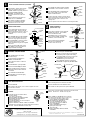
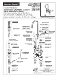
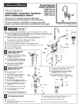
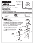
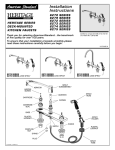
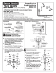
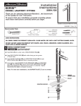
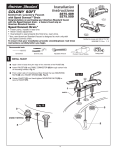
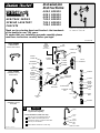
Installation
Instructions
4800
4801
4802
7830
7831
7890
HERITAGE SERIES
SPREAD LAVATORY
FAUCETS
SERIES
SERIES
SERIES
SERIES
SERIES
SERIES
Certified to comply with ANSI A112.18.1M
U.S. Patent No. 5,819,789
Thank you for selecting American-Standard...the benchmark
of fine quality for over 100 years.
To ensure that your installation proceeds smoothly--please
read these instructions carefully before you begin.
34312M-D
4800 SERIES
4801
SERIES
HERITAGE
SPOUT
W/POP-UP
CONVENTIONAL
SPOUT LESS POP-UP
LIFT
ROD
WRENCH
AERATOR
HANDLE
SCREW
RUBBER
GASKET
O-RING
ESCUTCHEON
RUBBER
RING
7831 SERIES
RUBBER
WASHER
GOOSENECK SPOUT
WITH POP-UP
VALVE
ASSEMBLY
RUBBER
WASHER
CARTRIDGE
RETAINER
LOCKNUT
STOPPER
SEAL
WASHERS
BRASS
WASHER
O-RING
TUBE & TEE
ASSEMBLY
FLANGE
LOCKNUT
DRAIN
GASKET
SCREW
DRAIN
WASHER
THUMBSCREW
EXTENSION
DRAIN
NUT
EXTENSION
ROD
DRAIN
BODY
CLIP
COUPLING
NUT
PIVOT
ROD
7890 SERIES
TAILPIECE
GOOSENECK SPOUT
BAR SINK
1
CAUTION
Turn off hot and cold water
supplies before beginning.
SPOUT ASSEMBLY (Model 7890 only)
Apply the grease (provided) liberally to the
SPOUT O-RINGS and SNAP RING areas.
Assemble the SPOUT and tighten SPOUT NUT
until snug on VALVE BODY.
Tighten BRASS LOCKNUT on center body.
SPOUT
SPOUT
NUT
SPOUT
O-RINGS
SNAP
RING
ESCUTCHEON
Printed in Mexico
1
SPOUT OR BASE ASSEMBLY (continued)
SHANK
Push SCREW into TEE and tighten SCREW
onto SHANK to secure SPOUT connection.
RUBBER
Insert BASE or SPOUT shank through
GASKET
center hole of SINK, making sure
RUBBER GASKET is properly positioned.
SPOUT
Place WASHERS inside COUPLING NUTS
and connect HOSE to each valve outlet.
Tighten COUPLING NUTS.
Assemble RUBBER WASHER,
RETAINER, and LOCKNUT onto
threads of SPOUT from underside
of SINK.
Insert LIFT ROD through SPOUT (or
BASE) and slot of RETAINER.
RETAINER
Align SPOUT and tighten LOCKNUT.
Be sure slot in BRASS WASHER is
positioned to the rear as shown.
2
Refer to separate "Instruction Sheet" for assembly of handles.
3
ESCUTCHEON
RUBBER
RING
LEDGE
PUTTY
Hold DRAIN PLUG to prevent turning
and assemble GASKET, WASHER, and
LOCKNUT, from underneath sink.
RUBBER
WASHER
BRASS
WASHER
Set VALVE BODIES so that their outlets
are facing toward center of SINK.
Tighten LOCKNUT using wrench supplied
with faucet.
FLANGE
DRAIN ASSEMBLY
(Model 4802 only)
DRAIN
PLUG
RUBBER
GASKET
WASHER
Insert threaded end of TAILPIECE
into lower end of DRAIN PLUG.
Connect other end to trap.
LOCKNUT
LOCKNUT
VALVE
BODY
Before connecting TEE make certain
that O-RINGS are properly seated on
stepped SHANK and SCREW.
INSTALL POP-UP DRAIN
TAIL
PIECE
Position EXTENSION ROD onto POP-UP
ROD and tighten THUMBSCREW.
STOPPER
Push TAILPIECE down into TRAP
(threaded end up).
FLANGE
Thread LOCKNUT, WASHER and
GASKET onto DRAIN BODY.
SINK
Remove one end of CLIP from PIVOT ROD
by squeezing ends together while sliding.
Insert PIVOT ROD into second or third hole
in EXTENSION and reassemble CLIP.
(EXTENSION may need to be bent.)
PUTTY
Adjust STOPPER height by repositioning
EXTENSION and tightening THUMBSCREW.
Apply a bead of PUTTY to underside
of FLANGE.
GASKET
POP-UP ROD
THUMBSCREW
Feed DRAIN BODY up through SINK
and thread FLANGE fully onto BODY.
Tighten LOCKNUT firmly, keeping the
PIVOT ROD pointed towards the back
of the SINK.
SINK
Apply a bead of PUTTY around underside
of DRAIN PLUG flange. Insert DRAIN
PLUG into SINK drain hole.
5/16''
MIN.
Place RUBBER RING into ESCUTCHEON
and screw ESCUTCHEON onto VALVE
BODY until snug against internal stop.
4
SCREW
LOCKNUT
VALVE INSTALLATION
Insert VALVE BODY through hole from
underside of SINK. Thread of VALVE
BODY should extend at least 5/16 inch
above SINK top. If necessary, adjust
LOCKNUT.
TEE
O-RING
Connect HOT water supply to the left VALVE
and the COLD water to the right VALVE using
sealant and appropriate connectors and
coupling nuts.
RUBBER
WASHER
SINK
O-RING
WASHER
CLIP
LOCKNUT
EXTENSION
ROD
EXTENSION
ROD
PIVOT
ROD
Drop STOPPER into DRAIN BODY.
TAILPIECE
Pull TAILPIECE up and thread tightly
into DRAIN BODY.
DRAIN
BODY
CLIP
TAILPIECE
TRAP
PIVOT
ROD
TRAP
5
6
Operate both handles to flush water lines thoroughly. Check
spout mounting and hose connections for leaks.
TEST INSTALLED FAUCET
Remove AERATOR.
Operate LIFT ROD and check DRAIN for leaks.
With handle in OFF position, turn on water supplies and check
all connections for leaks.
Turn handles into OFF position and replace AERATOR.
SERVICE
STOP
WASHER
To change direction of handle rotation,
proceed as follows:
Turn valve to OFF position.
Remove INSERT and HANDLE SCREW.
Slip HANDLE with ADAPTER off.
Remove SPRING CLIP.
Lift STOP WASHER, turn 90° and replace.
Replace SPRING CLIP.
Replace ADAPTER, HANDLE, SCREW, and INSERT.
SPRING
CLIP
AERATOR may accumulate dirt causing distorted and reduced
water flow. Remove AERATOR and rinse clean.
HOTLINE FOR HELP
For toll-free information and answers to your questions, call:
If spout drips, operate handles several times from OFF to ON
position. Do not force - handles turn only 90°.
Plastic SCREEN in CARTRIDGE may accumulate
dirt causing reduced water flow. To clean, first
turn off hot and cold water supplies, then:
Remove INSERT and HANDLE SCREW.
Slip HANDLE with ADAPTER off.
Unscrew CARTRIDGE with wrench.
Thoroughly rinse plastic SCREEN at
base of CARTRIDGE.
Replace CARTRIDGE until flange is
tight against valve body.
Turn valves OFF.
Replace ADAPTER, HANDLE, SCREW,
and INSERT.
CARTRIDGE
SCREEN
1 (800) 223-0068
Weekdays 8:00 a.m. to 7:00 p.m. Eastern Time
Saturdays 8:00 a.m. to 4:00 p.m. Eastern Time
Product names listed herein are trademarks of American Standard Inc.
© American Standard Inc. 1999
34312M-D