1
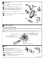
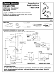
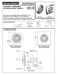
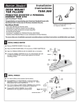
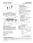
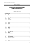
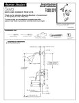
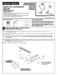
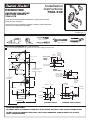
Installation
Instructions
PRINCETON
T508.50X
PRESSURE BALANCING
BATH AND SHOWER
TRIM KITS
Thank you for selecting American-Standard...the benchmark of fine
quality for over 100 years.
To ensure that your installation proceeds smoothly-- please read these
instructions carefully before you begin.
Certified to comply with ANSI A112.18.1
M968841 REV. 1.4
RECOMMENDED TOOLS
Phillips Screwdriver
Channel Locks
Adjustable Wrench
Plumbers' Putty or Caulking
Teflon Tape
Flat Blade Screwdriver
ROUGHING-IN DIMENSIONS (For reference only)
To assure proper positioning in relation to wall, note roughing-in dimensions.
3-5/8" REF.
SHR. 1/2" NOM.
COPPER SWEAT
1-5/8" TO 3-1/4"
5-1/2" REF.
INLETS
4-1/16"
INLETS
1/2" NOM.
COPPER
SWEAT
SWEAT
INLETS
1/2" NPT
2"
4-1/16"
4-7/8" REF.
TUB 1/2" NOM.
COPPER SWEAT
FINISHED
WALL
OPTIONAL TO FINISHED
FLOOR USUALLY
BETWEEN 65'' AND 78'
SWEAT
INLETS (STOPS)
8-1/2" REF.
5-7/8"
SHR. 1/2" NOM.
COPPER SWEAT
"SEE ILLUSTRATION "
4-1/16"
TUB 1/2" NOM.
COPPER SWEAT
74" FOR HEAD
CLEARANCE
INLETS
1/2" NOM.
COPPER
SWEAT
6-3/4"
OUTLETS
1/2" NPT
INLETS 1/2" NPT
5-7/8"
3-3/8"
18" OPTIONAL
1-1/2" REF.
INLETS
1/2" NPT
3-3/8"
1/2" COPPER
5-1/8" REF.
4"
3-3/8"
OUTLETS
1/2" NPT
TOP OF TUB RIM
BOTTOM OF TUB
THREADED INLETS
THREADED INLETS (STOPS)
CARE INSTRUCTIONS:
DO: SIMPLY RINSE THE PRODUCT CLEAN WITH CLEAR WATER. DRY WITH A SOFT COTTON FLANNEL CLOTH.
DO NOT: CLEAN THE PRODUCT WITH SOAPS, ACID, POLISH, ABRASIVES, HARSH CLEANERS, OR A CLOTH
WITH A COARSE SURFACE.
1
INSTALL TRIM
When finished tiling the wall, remove PLASTER GUARD (3).
Push on CAP (1).
4
3
5a
Mount ESCUTCHEON (2) and with SCREWS (7).
Install HANDLE (8) by pushing it onto CARTRIDGE STEM (9)
and tightening SET SCREW (10) from below with 2.5mm
Hex Wrench supplied. Insert INDEX BUTTON (11).
5
2
Remove cap from tub supply and plug from shower pipe.
Install SHOWER ARM with FLANGE (4) and SHOWER HEAD (5, 5a).
9
1
Install DIVERTER SPOUT (6).
7
8
10
11
6
2
ADJUST HOT LIMIT STOP
HOT LIMIT SAFETY STOP ADJUSTMENT
By restricting handle rotation and limiting the amount of hot water allowed to mix with the cold, the HOT LIMIT SAFETY STOP
reduces risk of accidental scalding. To set the maximum hot water temperature of your faucets, all you need to do is adjust
the setting on the HOT LIMIT SAFETY STOP.
Use a flat blade screwdriver or your fingers to pull up and rotate red HOT LIMIT SAFETY STOP (1). Follow Step "A" or "B" to
adjust min./max. discharge temperature. "0" being the hottest to "7" the coldest temperature setting. Factory set at "0".
"A"
"A"
TEMPERATURE SETTING NUMBERS
0
1
2
"B"
ADJUSTMENT WHEN WATER IS TOO HOT
PRY RED RING FORWARD AND ROTATE
COUNTER-CLOCKWISE ONE CLICK
3
4
ADJUSTMENT WHEN WATER IS TOO COLD
PRY RED RING FORWARD AND ROTATE CLOCKWISE
5
6
"B"
1
"RED RING"- HOT LIMIT SAFETY STOP
3
SERVICE
1
If faucet drips, operate handle several times from "off"
to "on". Do not apply excessive force.
Clogged CARTRIDGE (4) inlets may cause reduced flow in "full
on" hot or cold. To clean inlets, first turn off water supply, then:
Remove HANDLE (1), CAP (2) and CARTRIDGE (4). Clean inlets
and MANIFOLD (5).
Reassemble CARTRIDGE (4), alternately tightening SCREWS (3).
Replace CAP (2) and HANDLE (1). Check flow.
2
4
3
5
M968841 REV. 1.4