1
dimmPCITM 68VZ328
Hardware / Software
Manual
www.amctechcorp.com
AMC Technologies Corporation, July 2003
Revision 0.5.3 for SDK 2.05 Linux Kernel 2.0
Copyright notice
dimmPCITM System Development Kit CD-Rom, the text and graphics used in this manual, its cover, CD-Rom
artwork, dimmPCITM / Passive Backplane circuit board artwork and the box artwork represent proprietary,
patentable and copyrighted materials and are protected from misuse under local and international laws. All rights
are reserved.
AMC Technologies Corporation has license to reproduce this work. All rights reserved. No part of the publication may be reproduced, stored or transmitted in any form or by any means electronic, mechanical, photocopying, recording, scanning, or otherwise without prior written permission of the authors.
Contact Information
AMC Technologies Corporation, the Authors and Manufacturers of the dimmPCITM, dimmPCITM System
Developers Kit CD-Rom and this manual can be contacted at:
AMC Technologies Corporation
9741 - 54 Avenue
Edmonton, Alberta
Canada T6E 5J4
Phone: (780) 408-8840
Fax: (780) 408-8844
Internet: www.amctechcorp.com
dimmPCITM Software Development Kit
Copyright © AMC Technologies Corporation
This program is free software; you can redistribute it and/or modify it under the terms of the GNU General
Public License as published by the Free Software Foundation; either version 2 of the License, or (at your option)
any later version.
This program is distributed in the hope that it will be useful, but WITHOUT ANY WARRANTY without even
the implied warranty of MERCHANTIBILITY or FITNESS FOR A PARTICULAR PURPOSE. See the GNU
General Public License for more details.
A copy of the GNU General Purpose License is included in Appendix C of this manual. If you’d like another
copy write to the Free Software Foundation, Inc., 675 Mass Ave, Cambridge, MA 02139, USA.
2
www.amctechcorp.com
NETdimm Developers Kit Quick Start Guide
This document is provided to help users bring up the NETdimm Developers Kit hardware and
software as quickly as possible. If difficulties are encountered using this guide please refer to the
complete instruction manual.
1.
2.
3.
4.
5.
6.
7.
8.
Find a static-free work area to use and remove the dimmPCI Developers Backplane,
NETdimm, IOdimm and POWERdimm from their static protective bags.
Insert the NETdimm module into the System Slot (see figure below) on the backplane, the
one closest to the screw terminal connectors. Insert the POWERdimm into the slot
opposite the NETdimm. Ensure the modules are fully seated and the side tabs are
snapped closed and that the modules are in the proper slots.
Warning: Placing the modules in the incorrect slot may result in damage to the modules.
Please verify that the modules are in the correct slot before continuing. The POWERdimm
must be placed in the power slot (expansion slot 3) and the IOdimm (if used) must be
placed in expansion slot 2. The NETdimm can be placed in either the system slot or
expansion slot 2.
Connect the Serial Adapter Cable (DB9 on one end, 10 pin header on the other) to the
backplane connector JP5; the red strip on the cable should match up to the dot on the
backplane next to the connector. These both denote pin number 1.
Use the supplied serial cable to connect the Serial Adapter Cable to the development
computer. Please note which serial port the cable is connected to (ie. COM1 or COM2)
Note: the development computer must be running Linux to be able to use the development
tools supplied.
CAUTION: Failure to follow the following instructions may result in damage to the
NETdimm module or backplane. Jumper pins 7 and 8 together on JP7, the power jumper
to supply the POWERdimm with power. Ensure that the wall adapter is NOT plugged in
and connect the negative wire of the adapter to GND on the power connector and the
positive wire of the adapter to VIN on the power connector. Do not plug in the wall
adapter at this time.
At this point the hardware is properly configured and it is time to install the development
tools. Insert the dimmPCI SDK CDROM into the computer and mount it on the
filesystem.
From the root of the CDROM type make install to install the development tools to the
www.amctechcorp.com
3
computer.
9. Ensure the EMU BRK jumper is not installed.
10. Open the Linux “minicom” application. Select the serial port attached to the development
kit and configure the port for 115.2 kbps and 8N1 serial protocol. Power up the wall adapter.
The terminal window will act as the controlling console for the NETdimm.
11. After booting up, the console will display a login prompt, as is shown below
/etc/issue
2002
www.dimmpci.com
2 April
Welcome to AMCTC’s dimmPCI running uClinux!
See the following web sites for more information:
www.dimmpci.com: information specific to the dimmPCI platform
www.uclinux.org: information and tools for generic uClinux
dimmPCI login:
12. Enter the username root and the password is blank, just press enter.
That’s it; the development kit will act like a normal linux system now and is ready to be used to develop
powerful new embedded applications.
4
www.amctechcorp.com
www.amctechcorp.com
5
This page left intentionally blank
6
www.amctechcorp.com
1
Introduction
Launching Linux at the embedded
The modern world runs on computers and technology. Every corner you turn, every road you
travel, computers are helping you get there. Embedded systems are the fuel in these computers
and the lifeblood of modern-day electronics. So what is an embedded system? An embedded
system is a combination of computer hardware and software, and perhaps additional mechanical
or other parts, designed to perform a dedicated function. In some cases, embedded systems are
part of a larger system or product, as is the case of the joystick control system in the B2 Stealth
Bomber.
Embedded systems come in different sizes and packages. There are systems that can fit on a
dime and systems that won’t fit in your closet. Each system has available to it a wide variety of
computing power and a large diversity of functionality. These systems allow the technologically
inclined the ability to control and perform repetitive tasks with more reliability and accuracy than
any other methods previously used.
So how are these systems created? Engineers and firmware experts develop embedded systems.
These specialists write thousands of lines of instructions and program these systems with the
instructions using various software packages. These instructions can be written in C, assembler
or any other variety of programming language. These languages are available under Linux,
Windows and many other operating systems. When these systems are programmed, the
instructions become embedded in the memory of the system, thus the embedded system is
created.
Now the question is how can the designer program these systems in a way that is easy for the
end user to operate and inexpensive for the designer to produce. The simple solution is to
embed Linux.
Linux provides dependability, flexibility and scalability. Linux is a proven dependable architecture that several companies have grown to use and excel with. Linux’s flexibility is proven in its
ability to support a huge number of microprocessors, hardware devices, graphics devices and
applications. Finally, the scalability of Linux is beneficial because it spans a wide range of
computing functions. For example, mini web servers all the way up to large mainframe computing
systems use Linux or Unix based structure.
www.amctechcorp.com
7
Besides all of the impressive features of Linux, it is also openly available in several different
arrangements and configurations. This diverse array of compatibility of Linux and its supporting
software has evolved to the needs of the market and applications of which Linux is being
adapted.
One of the most interesting qualities of embedded Linux is the abundance of architectures that it
is compatible with. Linux has been ported to such architectures as x86, MIPS, and the PowerPC.
So, how do you decide which architecture to use? That depends; in the dimmPCITM we’ve
chosen to take advantage of the Motorola 68VZ328 DragonBall architecture.
The one thing to recognize about a Linux system is that all versions are basically variations of
the same idea. This means that all Linux systems are essentially compilations of the same basic
components. These components can include the kernel, libraries, drivers, command shells, GUI,
and utilities.
So what makes these distributions different? The differences can be found by examining the
core of each Linux version. These versions can contain different utilities, modules, kernel
patches, etc. These distributions are also differentiated in the way that they are installed,
configured, maintained and upgraded.
The dimmPCITM hardware introduces the user to the world of embedded Linux in a complete and
efficient way that is easy for the user to comprehend. By supplying a finalized, component level
solution that can be plugged into a DIMM socket to enable the user the functions described
above almost anyone can be using and manipulating an embedded system. The dimmPCITM
along with the passive backplane can be the solution to your engineering system or it can simply
be the add-on you need to complete your process. Either way, the dimmPCITM will greatly reduce
your engineering design costs and your time to market.
8
www.amctechcorp.com
What’s on the CD?
On the CD you will find:
µClinux source files with patches to work on the dimmPCITM platform.
GCC cross compiler tools for the DragonBall processor, with the necessary library files
included.
• Tools for use under µClinux on the target board, along with source code.
• A flash loader program, to reprogram the board with new image files.
• Sample applications to show the capabilities of the dimmPCITM development kit.
• Application notes describing how to configure dimmPCI modules for communication, use an
LCD with a NETdimm, setup dimmPCI modules for Digital I/O, use multiple NETdimms,
and how to use Digital and Analog I/O with the IOdimm.
•
•
System Requirements
The dimmPCITM System Development Kit requires a Linux host computer to be the development
workstation.
115200 bps serial port
• CD-ROM Drive
• 10Base-T ethernet (optional but recommended)
• x86 Linux machine (we support RedHat 7.0 and 7.1)
• Redhat Package Manager (RPM)
• GCC compiler tools
A working knowledge of the Linux operating system is highly recommended
•
www.amctechcorp.com
9
This page left intentionally blank
10
www.amctechcorp.com
2
dimmPCITM
uC68VZ328 Embedded Microcontroller
Features
CPU Module
•
•
•
•
•
•
•
•
•
•
•
•
•
•
•
Powerful 33 MHz DragonBall microprocessor
Up to 32 Mbytes SDRAM
Up to 8 Mbytes Simultaneous Flash Memory
Up to 1kbyte of serial EEPROM
168 pin DIMM form factor
Less than 500 mW power dissipation
Real Time Clock
Dallas Watchdog Timer
On board µClinux OS including TCP/IP
2 serial ports
Proposed dimmPCITM standard bus
Proposed dimmSPITM standard bus
33 MHz PCI performance
32 bit PCI data transfers
Ethernet interface
Backplane
•
•
•
•
•
•
•
Graphical “PDA Style” LCD module interface
USB ready
Low cost PCI compatible devices
Expandable and highly configurable
Excellent price/performance ratio
Ethernet interface
Economical
www.amctechcorp.com
11
General Description
AMC Technologies Corporation (AMC) has developed the proposed dimmPCI™ standards
specification which defines electrical signaling and mechanical specifications for a new generation of low cost Peripheral Component Interconnect (PCI) compatible devices. DimmPCI™ is an
adaptation of the PCI Specification 2.1 for embedded applications. All dimmPCI™ cards are
peripheral interface cards that install directly on a low cost backplane. The cards share the same
physical size as the module described in the JEDEC Dual Inline Memory Module (DIMM)
specification for a 168 pin DIMM module.
Due to the high volume, low cost nature of the connector, dimmPCI™ sets new price/performance milestones for embedded systems developers. The interface cards communicate using
standard PCI bus signaling and are compliant with the 33Mhz, 32-bit PCI bus specification.
The dimmPCI™ technology is applicable when facing tight budgets and demanding technical
requirements. In addition to the processor slot, up to four other dimmPCI™ slots are available
for expansion cards. There are a large variety of expansion cards to select from including analog
I/O, digital I/O and special communications functions. This highly configurable and economical
platform allows users to develop custom solutions at commercial-off-the-shelf prices.
AMC provides engineering support for the dimmPCI™ technology and can assist in developing
and supporting products that utilize this architecture. AMC has initiated the development of the
proposed dimmPCI™ standard and can assist in adopting this technology in application specific
areas. AMC also provides engineering support and manufacturing for other networked industrial control applications and product lines.
CPU Module Description
The AMC Dragonball dimmPCI™ CPU module is a cost effective solution for technically demanding applications. This dimmPCI™ module is designed around the powerful and economical
DragonBall VZ microprocessor.
The CPU module can contain up to 32 Mbytes of SDRAM, 8 Mbytes of flash and 1kbyte of
EEPROM. Also included on the CPU module are a real time clock, a watchdog timer and 2 serial
ports.
12
www.amctechcorp.com
The Dragonball dimmPCI™ CPU module supports Ethernet 10BaseT, two serial ports, and a
graphical “PDA style” LCD interface. The module conforms to the proposed dimmPCI™ standard and may be used with a complementary array of other modules on a dimmPCI™ backplane.
These expansion cards include a COMM module that supports dual Ethernet 10/100BaseT
channels and CAN communications, a DAIO module that supports digital and analog I/O, and a
power supply module.
AMC provides engineering support for the Dragonball dimmPCI™ CPU module and can assist in
developing and supporting hardware and software for specialized applications. This CPU
module is programmable using the industry standard ‘C’ programming language and utilizes the
very reliable Linux operating system. AMC has extensive experience in applying Linux to
Internet appliance applications. AMC also provides engineering support and manufacturing for
other industrial control applications and product lines.
The CPU module can be obtained with or without the PCI on board.
Backplane Description
The AMC dimmPCI™ 3U Backplane forms a versatile foundation for cost-effective rapid application development for a wide variety of technically demanding applications. The backplane
conforms to the proposed dimmPCI™ standard and may be used with a complementary array of
dimmPCI™ modules. This economical platform allows users to develop custom solutions at
commercial-off-the-shelf prices.
The dimmPCI™ 3U Backplane has four available slots for expansion modules. Of the four slots,
three are dimmPCI™ slots and one is a standard 5V PCI slot. The dimmPCI™ slots support a
variety of expansion cards. The modules include:
A range of CPU modules with different microprocessor architectures and performance
COMM modules that support Ethernet 10/100BaseT, CAN, DeviceNet, Modbus and other
RS-232 and RS-485 based serial protocols
• DAIO modules that support digital and analog I/O
• A power supply module
•
•
The standard PCI slot supports any 3V or 5V 32-bit PCI expansion card.
The dimmPCI™ specification provides for user defined I/O signaling to each module. The
dimmPCI™ 3U Backplane makes these readily available so application developers have a
convenient way to access the I/O, reduce development costs and reduce time to market.
www.amctechcorp.com
13
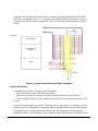
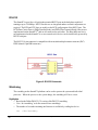
Architecture
68EC000 HCMOS
STATIC CORE
PWM
TIMER
SPI
UART
LCD
NETdimm
RS-485
MC68VZ328
RS-232
FLASH
EE
PCI
SDRAM
ETHERNET
RTC
Figure 1. CPU Architecture
DIMM
DIMM
RJ-45
ETHERNET
BATTERY
PCI
DIMM
USB
RS-232
LCD
Figure 2. Backplane Architecture
14
www.amctechcorp.com
POWER
GENERAL
PURPOSE I/O
RS-485
PS-2
keyboard
The CPU Architecture consists of 4 main functional regions. The Ethernet Controller, the PCI
Interface, the MCU Core and System Memory. These regions form a highly integrated embedded
system. The Backplane Architecture consists of 3 main regions. The Communication Connectors, the DIMM and PCI Slots and the LCD Connector. These regions complete the dimmPCITM
system.
The MCU Core
The MC68VZ328 provides system designers more performance with the capability of running at
higher speed while achieving lower power consumption with a true static core. The MCU
features a fully static synthesizable FLX68000 Core Processor. This processor provides more
than 5 MIPS performance at 33MHz processor clock. The DragonBall VZ also provides a UART,
Timer/PWM, Parallel I/O, LCD Controller, DRAM/SDRAM Controller, SPI, and RTC.
System Memory
The module provides up to 8 MB of FLASH ROM and up to 32 MB of SDRAM. These are
configured as 16-bit wide memories. The SDRAM controller has been configured to use self
refresh and also supports CAS-before-RAS refresh cycles. Low power mode control also comes
into effect on the MC68VZ328.
The LCD utilizes the main system memory as the display memory. With SDRAM there is a single
LCD DMA cycle transfer.
Memory Map
The Dragonball VZ has four pairs of chip selects, CSA0 & CSA1, CSB0 & CSB1, CSC0 & CSC1,
and CSD0 & CSD1. Individual chip selects are not completely configurable; rather, the chip
selects are configured as pairs. Chip select pairs share a base address (the addressable region of
the second chip select begins immediately after the addressable region of the first), the size of
the addressable area (relative to the base address), the number of wait states, and whether it is
an 8-bit or a 16-bit chip select.
When SDRAM is enabled, the Dragonball VZ consumes five of the chip selects. CSB1, CSC0,
CSC1 become WE, RAS, CAS and CSD0, CSD1 become CS suitable for SDRAM only. The 16-bit
flash has been assigned to CSA0, because that is the only chip select active after reset. The wait
states are set for internal timing.
The 16-bit CY7C09449 PCI interface is a synchronous interface and must be attached to CSB0,
which is configured for external timing (“infinite” wait states).
www.amctechcorp.com
15
The RTL8019 ethernet chip supports either 8/16-bit interfaces, but because most NE2000 compatible drivers have been written for an 8-bit interface, the device has been interfaced as an 8-bit
device attached to CSA1, the last available chip select. Since the chip select pair must be
configured as 16-bit to support the 16-bit flash, the registers of the ethernet chip will appear at
every other byte address rather than a block of contiguous bytes. Said a little differently, each 8
bit register maps to a corresponding word address where only half of each word is used.
A d d re s s Ra n g e
0x00000000 to 0x000003FF
0x00000400 to 0x01FFFFFF
0x01FFFFFF to 0x0FFFFFFF
0x10000000 to 0x103FFFFF
0x11000000 to 0x107FFFFF
0x10800000 to 0x1FFFFFFF
0x20000000 to 0x2001FFFF
0x30000000 to 0x400000000
0x400000000 to amo u n t n ee d e d
en d o f PCI p e rip h erals to 0xFFFFEFFF
Fu n c tio n
in te rru p t v ec to r tab le
SDRA M (32 M B)
u n imp le men ted s p ac e
FLA SH ROM
Re altek Eth e rn et/CA N/USB
Co n tro lle r
u n imp le men ted s p ac e
PCI
PCI I/O ma p p e d p erip h e ra ls
PCI me mo ry map p ed p erip h erals
u n imp le men ted s p ac e
Ch ip Sele ct
CSD0 (CSD1)
CSA 0
CSA 1
CSB0
Figure 3. Memory Map
I/O Memory
The mapping of the I/O Memory into the CPU’s main memory takes place at 2 different locations.
At 0xFFFFF000 the DragonBall VZ registers and boot microcode fill the available memory to the
end of the CPU memory. For more detailed information on the DragonBall VZ Registers and the
DragonBall VZ Boot Microcode consult the DragonBall VZ Users’ Manual (located on the CD).
The Ethernet controller on the NETdimm is mapped off the DragonBall VZ’s CSA1 chip select,
and is located at 0x10400000. Programming information for the Realtek RTL8019AS Ethernet
Controller is not included in this document and may be found in the RTL8019AS Datasheet
(located on the CD).
FLASH ROM
The Flash ROM used on the dimmPCITM is the AMD29DL322D or compatible 3.0V FLASH ROM.
The exact Flash part or size is dependant on the current FLASH in stock or available on the
market. The Flash is located at 0x10000000 in memory.
16
www.amctechcorp.com
A portion of the Flash has been allocated for use with the Journaling Flash File System (JFFS).
The JFFS is mounted under the ‘/usr/’ directory in the standard µClinux distribution. For more
information on the JFFS consult Appendix B. The rest of the Flash contains the read-only file
system.
10000000
Linux Kernel
Read-Only File
System
JFFS
Figure 4. Layout of the Flash and Flash Schematic
Layout of the Flash
Flash memory stores the following system components:
• The Linux kernel, located at the beginning of flash.
• The root file system as a read-only file system situated immediately after the kernel.
• The Journaling Flash File System, which starts on the first sector boundary after the root file
system.
No special consideration is given to the Flash boot sectors, since there is no monitor or special
bootstrap. At reset, Flash memory is located at address 0x00000000 and is mirrored throughout
the memory since it is controlled by chip select CSA0. At bootup, the kernel, being at the
beginning of flash, is run immediately. One of the first actions of the kernel is to define the flash
www.amctechcorp.com
17
to its working position in the memory map and to initialize SDRAM to address 0x00000000.
SDRAM
The SDRAM used on the dimmPCITM is the MT48LC4M16A2 or compatible 3.0V SDRAM. The
exact SDRAM part or size is dependant on the current SDRAM in stock or available on the
market. The SDRAM is located at 0x00000000 in memory so that the interrupt vector table will be
located in SDRAM.
* NOTE * Setting the registers to recognize different SDRAM sizes doesn’t work as explained in
the Motorola Application Note AN2148-D rev 5.0. Instead a few jumper resistors select the
SDRAM size.
Figure 5. SDRAM Schematic
18
www.amctechcorp.com
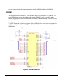
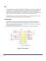
Ethernet Controller
The dimmPCITM contains an on board RealTek RTL8019AS Ethernet controller and all the
supporting circuitry to implement a 10BaseT ethernet port with no external components. The
drivers have been written and implemented by the µClinux operating system running on the
dimmPCITM. No support is provided with the exception of the AMC Technologies Corporation
provided IEEE assigned MAC address. Below shows how the MAC address can be obtained.
The ethernet 8-bit peripheral is attached to the 16-bit chipset via chip select CSA1 as explained in
the memory map section.
Viewing the Ethernet MAC ID
One way to view the MAC ID is to simply reboot. One of the boot messages that scroll past
displays the MAC ID.
A utility exists called ‘ifconfig’ that when executed displays the current network information.
‘ifconfig’ displays “hwaddr” which is the MAC ID of the module. There are two utilities to set
the IP address as outlined in Section 3.
www.amctechcorp.com
19
Figure 6. NETdimm Ethernet Schematic
20
www.amctechcorp.com
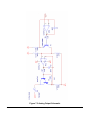
Digital I/O
The Motorola MC68VZ328 processor provides numerous general purpose I/O lines to the dimmPCITM.
The lines which have not been assigned to their dedicated functions can be used for digital I/O.
Depending on the options compiled into the kernel, a number of pins on the dimmPCITM module can be
used for digital I/O. The configuration procedure for setting up the digital I/O functions is outlined in
Appendix D1.
IOdimm
The IOdimm module can be used as a stand-alone or as a peripheral dimmPCI device. Instructions for
setting up the IOdimm to be used as a peripheral device are provided in Appendix D2.
The IOdimm provides general purpose input and output. The IOdimm can provide up to 8 digital
inputs, 4 digital outputs, 8 12-bit analog inputs and 2 12-bit analog outputs. Figures 7.1-7.4 shows the
schematics for the digital and analog I/O. The IOdimm also have general purpose I/O lines that are
provided by the Motorola processor as mentioned earlier. However, the IOdimm has its own driver for
the SPI pins and therefore these pins will not be available for use by this driver (refer to Digital I/O
application note in Appendix D).
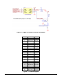
The MAX1203 pic is used to convert analog signals to digital signals and the TLV5618A is used to
convert digital signals to analog signals. The schematices for the digital to analog converter (DAC)
and the analog to digital converter (ADC) are shown in Figures 7.5 and 7.6 respectively.
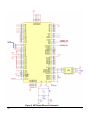
The IOdimm signals are summarized in Figure 7.7. Only pins 1-29 are described in the table. Pins 30-84
have the same signals as the NETdimm. Those signals are shown in Figure 10.
www.amctechcorp.com
21
Figure 7.1 Digital Output Schematic
Figure 7.2 Digital Input Schematic
22
www.amctechcorp.com
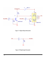
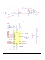
Figure 7.3 Analog Output Schematic
www.amctechcorp.com
23
Figure 7.4 Analog Input Schematic
Figure 7.5 Analog to Digital Converter Schematic
24
www.amctechcorp.com
Figure 7.6 Digital to Analog Converter Schematic
Pin #
SideA
SideB
1
Analog In 0 Analog In 1
2
Analog In 2 Analog In 3
3
VIO
VIO
4
VIO
VIO
5
6
7
8
9
Analog In 4 Analog In 5
vbatt
earth gnd
Analog In 6 Analog In 7
emu brk
vee
Analog Out 0 Analog Out 1
10
UART 2 a+
11
UART 1 rts UART 1 cts
12
UART 1 rx
UART 1 tx
13
ee clk
ee mosi
14
UART 2 b-
ee miso
15
Digital In 0
Digital In 1
16
Digital In 2
Digital In 3
17
Digital In 4
Digital In 5
18
Digital In 6
Digital In 7
19
Digital Out 0 Digital Out 1
20
Digital Out 2 Digital Out 3
Figure 7.7 IOdimm Signals
www.amctechcorp.com
25
RS-232
The dimmPCITM provides a 10-pin header terminal RS232 port on the backplane capable of
running at up to 230400bps. RS232 line drivers are integrated and no external components are
required. The RTS and CTS lines are usable on the DCE configuration of the RS232 port. The
DCD (Data Carrier Detect), DSR (Data Set Ready) and DTR (Data Transmit Ready) lines are not
implemented on the dimmPCITM and are all connected to each other. The Ring Indicator line is
not implemented on the dimmPCITM so no external serial devices can be intrinsically powered by
RS232 serial port.
The RS-232 10-pin connector is compatible with an insulation displacement connector (IDC)
DE9S (female 9-pin DB9 connector)
Figure 8. RS-232 Schematic
Watchdog
The watchdog on the dimmPCI platform can be used to protect the system and individual
processes. When the process or the system hangs, the watchdog will force a reset.
Highlights
• Based on the Dallas DS1832 (3V version of the DS1232) watchdog
• Uses ‘/dev/watchdog’ as do the normal Linux watchdogs.
• The number of seconds remaining until timeout is available by reading the device.
cat
26
/dev/watchdog
www.amctechcorp.com
Multiple processes may be individually registered with the watchdog, each providing its own
timeout time. Each process must update the watchdog within its own timeout interval or the
system will reset.
• A process may unregister itself at any time.
• At least one process must register with the watchdog within 3 minutes of bootup or else the
watchdog will reset the system. If ‘/sbin/watchdog &’ is specified in the ‘/etc/rc’ file, it will
register itself and keep the watchdog happy indefinitely (until another process registers itself).
•
Usage
Processes to be protected will register using the ‘WATCHDOG_REGISTER’ IOCTL. The
process passed is the desired number of seconds before timeout. The ID (required for
watchdog update and deregistration) is passed out.
Update the timer with the ‘WATCHDOG_TICKLE’ IOCTL. The ID provided by the
registration is passed in.
Before the process exits, it should deregister itself with the
‘WATCHDOG_UNREGISTER’ IOCTL. The ID provided by the registration is passed in.
For example code see Appendix A.
www.amctechcorp.com
27
SPI
A standard SPI bus is included on the dimmPCITM. This SPI bus is located on the DIMM socket
occupying pins 23-29 on both the A and B-sides. The SPI bus allows developers the opportunity to create their own DIMM socket cards containing SPI devices and the availability to
interface these cards with the dimmPCITM. The SPI bus provides an easy and affordable low-cost
alternative to PCI. However the SPI can only be used in low-bandwidth applications.
Currently in this version of the software development kit, we are not providing any drivers for
the SPI. The official release will contain several generic SPI drivers.
LCD Interface
The dimmPCITM backplane has an LCD connector that is fully supported by the dimmPCITM
module. The LCD connector is designed for a 4-bit LCD panel. The LCD’s contrast can be
adjusted by sending a PWM signal over the LCONTRAST line. The device driver, in the future,
will allocate a block of memory for the LCD.
Information about how to hook up a LCD to the backplane can be found in Appendix D1.
Figure 9. LCD Schematic
28
www.amctechcorp.com
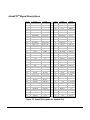
dimmPCITM Signal Descriptions
P in #
1
2
3
4
5
6
7
8
9
10
11
12
13
14
15
16
17
18
19
20
21
22
23
24
25
26
27
28
29
30
31
32
33
34
35
36
37
38
39
40
41
42
SideA
ET HRXET HRX+
SideB
ET HT XET HT X+
ET HLNKLED
VBAT
P /D
EMUBRK
Ground
SCIB+
SCIART S
SCIARXD
Reserved
LCONT RAST
LFRM
LCLK
LCD1
LCD3
Ground
USER
+5V
D+
+5V
SP IINT 0
CS1
CS3
MISO
Ground
SCLK
+3.3V (I/O)
AD[01]
Ground
AD[03]
AD[05]
+3.3V
AD[07]
AD[08]
M66EN
AD[10]
AD[12]
Ground
AD[14]
ET HACT L
EGND
EMUIRQ
EMUCS
Ground
SCIBSCIACT S
SCIAT XD
Reserved
Reserved
LLP
LACD
LCD0
LCD2
Ground
USER
DGround
SP IINT 1
CS0
CS2
SS
+5V
MOSI
Ground
+3.3V (I/O)
AD[00]
AD[02]
Ground
AD[04]
AD[06]
+3.3V
C/BE[0]#
AD[09]
Ground
AD[11]
AD[13]
+3.3V
P in #
43
44
45
46
47
48
49
50
51
52
53
54
55
56
57
58
59
60
61
62
63
64
65
66
67
68
69
70
71
72
73
74
75
76
77
78
79
80
81
82
83
84
SideA
C/BE[1]#
+3.3V
SERR#
+3.3V
P ERR#
LOCK#
Ground
DEVSEL#
+3.3V
IRDY#
Ground
C/BE[2]#
AD[17]
+3.3V
AD[19]
AD[21]
Ground
AD[23]
C/BE[3]#
+3.3V
AD[25]
AD[27]
Ground
AD[29]
AD[31]
+3.3V(I/O)
REQ#
Ground
CLK
Ground
CLK2
SYSEN#
RST #
+5V
INT D#
INT B#
+5V
REQ3#
REQ2#
Ground
REQ1#
-12V
SideB
AD[15]
P AR
Ground
SBO#
SDONE
+3.3V
ST OP #
Ground
T RDY#
Ground
FRAME#
+3.3V
AD[16]
AD[18]
Ground
AD[20]
AD[22]
+3.3V
IDSEL
AD[24]
Ground
AD[26]
AD[28]
+3.3V
AD[30]
Reserved
Ground
GNT #
+3.3V(I/O)
CLK1
Ground
CLK3
P RST #
+3.3V(I/O)
+5V
INT C#
INT A#
+5V
GNT 3#
GNT 2#
+12V
GNT 1#
Figure 10. dimmPCITM signals for System Slot
www.amctechcorp.com
29
Pins 1-5 on the DIMM socket control the Ethernet port on the NETdimmTM. Pins 6-8 control the InCircuit Emulator. Pins 9-13 control the UART port. Pins 14-20 control the LCD. Pins 21-22 control the
USB port. Pins 23-29 control the SPI. Finally, pins 30-84 control the PCI bus.
PCI
The PCI interface on the dimmPCITM CPU module is constructed around a Cypress
CY7C09449PV-AC bus controller. This controller is an integrated PCI bridge, master/slave direct
memory access controller (DMAC), message transport unit (I2O) and contains 32kbytes of dual
ported memory (DPRAM).
The local bus (LB) may access four areas with the CY7C09449; an 8K direct access window into
any of the PCI address spaces (memory, I/O or configuration space), the 32kbyte DPRAM, the
I2O FIFOs, and the control registers. Any PCI master may access only the last three areas;
further, PCI masters may not access the local bus (neither the CY7C09449 nor the 68VZ328
support this).
The DPRAM may be used as either source or destination for PCI DMA transfers, which may be
initiated locally (as a master) or by another host (as a target).
The CY7C09449 is attached to a 32-bit synchronous local bus. An Altera EPM7032AE FPGA is
required to attach the CY7C09449 to the 16bit asynchronous bus of the Dragonball VZ.
When the dimmPCITM CPU module is used in the system slot (slot 1), SYSEN line is pulled low;
the 7032AE performs various PCI central resource functions including RESET generation,
CLOCK generation and bus REQUEST and GRANT arbitration.
PCI BIOS
The PCI BIOS establishes a software interface between the PCI device drivers and the
CY7C09449 hardware. When the dimmPCITM CPU module is in the system slot, the PCI BIOS also
performs the scanning and initialization of devices attached to the PCI bus. Base memory and I/
O addresses are assigned, as are the shared PCI interrupt request lines.
Expansion ROMs (used by PC compatible video cards and the like) are not supported, as the
Dragonball does not support the x86 code.
The PCI BIOS includes the standard ‘pcibios_read/write_config_byte/word/dword’ functions.
All PCI spaces are defined to be small endian. The Dragonball, which is large endian, has been
attached to the C7C09449 such that word accesses do not require byte swapping; byte accesses
require toggling the least significant address bit. This is made transparent by the PCI BIOS and
30
www.amctechcorp.com
has been extended to include ‘readb/readw/readl and writeb/writew/writel’ functions.
The PCI BIOS also includes extensions to perform DMA transfers, and to manage the DPRAM.
Drivers may request a transfer using shared DPRAM. Drivers for high bandwidth devices may
request a private and permanent allocation of the DPRAM. The DMA mechanism allows the
device driver to block or not until the requested transfer(s) have completed. The PCI BIOS uses
interrupt driven code to manage the request queues.
PCI DRIVERS
The ‘/proc/pci’ may be used to display a list of active PCI devices.
Electrical Characteristics
•
•
Operating Voltage (nominal)
Operating Current
3.3VDC / 5VDC
75 mA @ 3V with PCI
36 mA @ 5V with PCI
Maximum Ratings
•
•
Operating temperature
Storage temperature
0 to +70 degrees C
-20 to +85 degrees C
www.amctechcorp.com
31
This page left intentionally blank
32
www.amctechcorp.com
3
uClinux Installation
Installing the dimmPCITM System
Builder Kit
Before beginning
This development kit requires an x86 compatible PC running some variant of linux. It will not
work under any version of Windows. If linux is not installed on your computer, Redhat linux can
be downloaded from http://www.redhat.com In addition root access is necessary for this entire
process due to the fact that regular users do not have adequate permissions.
Installation
Put the install CD in the CD-ROM drive, depending on the linux configuration the CD will likely
be available in either of the following directories.
/mnt/cdrom
/cdrom
If it is not automatically mounted to the file system, try this
mkdir /cdrom
mount -t iso9660 -o ro /dev/cdrom /cdrom
Approximately 60M free in your ‘/opt’ directory is needed for this next step. When the CD has
been mounted, go to the ‘/cdrom’ directory and type
make install
The Makefile will automatically install all the packages into the ‘/opt/’ directory. Should you at
any point wish to remove the dimmPCI SDK software from your computer, you mount the CDROM as previously described and run
make clean
www.amctechcorp.com
33
This will remove the development tools and their links. Note: any additional files that you may
have added to the SDK directories will also be removed.
Configuring and compiling the µClinux kernel
NOTE: this step must be completed before creating an image file.
The kernel source files are contained in the ‘/opt/uClinux/linux’ directory. From that directory the
operation of the kernel can be customized. Base configuration files are available in the ‘/opt/
configs’ directory. To use one of these configurations, copy the file to the ‘/opt/uClinux/linux’
directory and rename it to ‘.config’ (Note the period at the beginning of the filename). At this
point a backup copy of the existing kernel should be made, in case the new one doesn’t work.
cd /opt/uClinux/linux
cp linux.bin linux.bin.backup
To change the kernel options, use the make utility to configure the source code. NOTE: this
step must be followed even if not changes are being made to the configuration. Either a graphical
configuration process:
make menuconfig
or a command line style interface can be used:
make config
After the changes have been made or if a recompile of your kernel is needed for any reason, type
the following commands:
make clean
make dep
make linux.bin
These commands will create a new linux.bin file from scratch. Once this is done, a new
filesystem image should be created to take advantage of the new kernel.
34
www.amctechcorp.com
Creating a ROM image
Before using the development hardware a file system will need to be created for use on it. The ‘/
opt/fs’ directory contains the tools necessary to create a filesystem image. From this directory
run the Makefile. The first time you run this it will compile all the tools that will be used on the
dimmPCI platform itself, subsequently it will create an image for download.
make imagez.bin
An explanation of some of the more important files and sub-directories in the ‘/opt/fs’ directory:
imagez.bin
linux
romdisk
src
- this contains both the µClinux kernel and the filesystem,
ready to be programmed to the dimmPCI platform.
- a link to where the µClinux kernel source and binaries reside.
- the set of files that will make up the root file system on the
dimmPCI module.
- source code for each of the tools available on the dimmPCI module.
Any time after the files have been modified in the romdisk directory, typing the following will
create a new image file:
make imagez.bin
This will compress the filesystem and the ‘linux.bin’ kernel file into a single image file,
‘imagez.bin’. The one file is all that is necessary to program onto the dimmPCI CPU module in
order for it to operate properly.
Customizing the filesystem
Before programming the dimmPCI module for the first time, the filesystem should be configured
so that it does what is wanted from it the first time. These are the files, which control the startup
and initialization process in the filesystem. They are stored in the ‘/opt/fs/romdisk/etc’ directory.
The files are:
www.amctechcorp.com
35
inetd.conf
inittab
issue
passwd
rc
resolv.conf
services
- this file contains information on which internet services the board will
provide
- determines which program will handle communication on the serial ports
- the file that is displayed anytime someone tries to log onto the board
- contains login/password information, this file is ignored by the current
login program
- this script is run right after kernel initialization, anything that runs at
startup should be put in this file.
- stores the IP address of the current nameserver
- associates service names with port numbers for internet servers in
‘inetd.conf’
Initially the IP settings should be statically configured for the unit by commands in the ‘rc’ file.
Additionally an NFS mount can be set up at this point to save time. Look ahead at the guide to
using NFS for more information.
Accessing your dimmPCI development board via the serial port
Since the development board has no display or keyboard, the standard console has been routed
to the serial port. Using the serial port the development board can be controlled and monitored
similar to a linux PC.
36
1.
First take the serial cable out of the box and connect it between the development board
and the computer.
2.
Next run either ‘minicom’ or ‘xminicom’ on the PC, depending on whether X windows is
being used or not.
3.
Configure minicom to run at 115200 baud with 8N1 and no flow control.
4.
Finally power up the development board and a login screen should appear after a few
seconds.
5.
The username is root and the password is blank.
6.
Upon successful login you will see a ‘#’ prompt.
www.amctechcorp.com
Accessing the Network
The kernel supplied with the dimmPCITM CPU module supports TCP/IP networks (IPX is not
supported at this time). Before the network may be accessed, the dimmPCITM CPU module must
obtain an IP address.
The subnets 10.xxx.xxx.xxx, 172.16.xxx.xxx, and 192.168.xxx.xxx are reserved for local area networks.
Addresses are either statically assigned or dynamically allocated using DHCP (static IPs are still
possible as the DHCP server allows specific MAC ID to IP mappings). The dimmCPU module
may be configured with either a static or dynamic IP.
Static IP
A static IP is selected running ‘ifattach’ from the ‘/etc/rc’ script. The ‘ifattach’ is called first
without parameters to release any network bindings. The second call specifies the desired
address, mask and gateway, followed by the interface name (eth0). Network access is immediately available after the ‘ifattach’, therefore it is common practice to mount network drives with
subsequent lines in the /etc/rc file.
For example, to select the IP 192.168.10.141 on a network using the subnet 192.168.10.xxx, use:
/sbin/ifattach
/sbin/ifattach —addr 192.168.10.141 —mask 255.255.255.0 \
—net 192.168.10.0 —gw 192.168.10.1 eth0
* NOTE * the backslash may be used in a script file to break a long line over several lines.
Dynamic IP
A dynamic IP is obtained by running ‘dhcpcd’ from the ‘/etc/rc’ script. The ‘dhcpcd’ is called in
background mode with a number of parameters.
The ‘-p’ option forces the daemon to run in persistent mode, retrying indefinitely until an IP is
obtained; without it, the daemon will abort if a DHCP server cannot be located.
The ‘-c’ option specifies a command file (the functionality of this option deviates slightly from
www.amctechcorp.com
37
the typical 0.70 version of ‘dhcpcd’) which is executed when an IP is first obtained, or should the
IP address change (the common operation is to execute every time an IP lease is renewed). The
command is invoked with zero or more parameters. Often the command is ‘/bin/sh’, and the
parameter is a script file.
If the ‘-v’ option is specified, the IP address is written to ‘stdout’ as the command file is invoked.
Unlike ‘ifattach’, the IP address is not immediately obtained; the command file is executed when
the IP has been obtained. At this point, network access is available; therefore it is common
practice to mount network drives using the command file.
For example, the ‘/etc/rc’ file contains:
/sbin/dhcpcd -p -c /etc/dhcpcd.sh &
and the ‘/etc/dhcpcd.sh’ file contains:
echo “We have network access!”
/sbin/ifconfig
mount [...]
Accessing your dimmPCI development board via telnet
If the dimmPCITM development board is connected to an IP network, it can be accessed using
telnet, just like using a serial interface. To take advantage of this, the IP address of the board
needs to be known. It will be stored in the ‘/etc/rc’ file in the ‘romdisk’ directory. Suppose the
address of the board is 192.168.10.51. Type the following command.
telnet 192.168.10.51
A login prompt will appear. The procedure for logging in is the same as for the serial interface.
Enter ‘root’ as the username, and press ‘Return’ at the password prompt. Note that the telnet
access procedure is the same as that of the serial console connection.
Compiling your own source code
The cross compiler for the DragonBall processor onboard the dimmPCI module is installed along
with your kernel source and file system so it should be ready for use. In the ‘dimmpci’ directory,
create a new directory called source.
38
www.amctechcorp.com
cd ~/dimmpci
mkdir source
cd source
Create a simple ‘hello world’ C program called ‘hello.c’ such as this:
#include <stdio.h>
void main() {
printf(“Hello World\n”);
}
Now run the GCC compiler to create the binary file. Links should be set up so the compiler is in
the path. If not add ‘/opt/uClinux/bin’ to the path and everything should work fine.
m68k-pic-coff-gcc hello.c -o hello
Once the hello world program has been successfully compiled, copy the resulting binary file to
the romdisk directory and create a new image file.
cp ~/dimmpci/source/hello /opt/fs/romdisk/usr
cd /opt/fs
make imagez.bin
Now program the image file to the dimmPCITM CPU module and connect to it using the serial port.
Run the hello program in the root directory and, sure enough, it will print out ‘Hello World’.
You can use a ‘Makefile’ as well to automate the compiling process if you have multiple files or
special options, etc.
Using NFS to streamline the development cycle
If reprogramming of the dimmPCITM CPU module were necessary every time changes were made,
more time would be spent reprogramming than writing source code. Assuming that both the
linux PC and the dimmPCITM development board are connected via ethernet the solution is to
make part of the computer’s hard drive available on the dimmPCI filesystem using NFS. First an
entry will need to be added to the ‘/etc/exports’ file of the host computer similar to the following:
www.amctechcorp.com
39
/(home directory)/dimmpci/source
(rw)
Of course you will need to add the home directory. This will allow anyone read and write access
to that portion of the file system. This is acceptable if on a private network, but highly undesirable if the computer is on the internet. See the man pages for the exports file if the NFS share
needs to be secure.
After adding that line to the exports file a restart is necessary for the NFS server process, if it
was running in the first place, to load the changes made to the file.
For the next step, the IP address of the computer must be known. If it’s not known, in a console
window type ifconfig and a screen similar to this will appear:
eth0
Link encap:Ethernet HWaddr 00:50:BA:48:3E:D6
inet addr:192.168.10.34 Bcast:192.168.10.255
Mask:255.255.255.0
UP BROADCAST RUNNING MTU:1500 Metric:1
RX packets:11509 errors:0 dropped:0 overruns:0 frame:0
TX packets:2342 errors:0 dropped:0 overruns:0 carrier:0
collisions:0 txqueuelen:100
Interrupt:12 Base address:0x9400
In this case the IP address would be 192.168.10.34. Next mount the NFS share on the dimmPCI
file system. Depending on whether the dimmPCI CPU module is using DHCP or a statically
assigned IP address the following command will be placed in one of two configuration files. If a
static IP is being used, edit the ‘/opt/fs/romdisk/etc/rc’ file. Conversely if DHCP is being used,
this command will have to be placed in the ‘/opt/fs/romdisk/etc/dhcpcd.sh’ file. For a static IP
add the following toward the end of the file, right before the ‘exit 0’ line. For a DHCP system add
this line to the end of the dhcp command file.
/bin/mount -t nfs 192.168.10.34:/path/to/share /mnt
Of course the IP address will be different than the one in this example. Following the IP address
put the same path as is in the ‘/opt/fs/romdisk/etc/exports’ file. Once finished a new image file
may be created and programmed onto the dimmPCITM CPU module.
After rebooting the CPU module, there will be access to the files on the PC from the dimmPCI
development board in the ‘/mnt’ directory. Now code can be recompiled on the PC and the
binaries will be instantly available on the development board.
40
www.amctechcorp.com
Updating Applications on your dimmPCI module
There are two methods for updating applications on the dimmPCI module: (1) create a new image
file with the updated application, or (2) copy the updated application to the flash filesystem. Of
course the latter option will be preferable in most situations since it is faster and easier.
Method 1:
The first step is to copy the new application file(s) to the somewhere in the ‘romdisk’ directory
on the development computer. Next follow the procedure to create a system image file, and then
program it to the target dimmPCI module using one of the previously described methods.
Method 2:
Note: this method assumes the board has been connected to an IP network and the flash
filesystem is in use previous to this procedure.
Create an NFS share on the development computer that contains the updated application file(s).
Power up the target dimmPCITM module and log on to it using either the serial or telnet interface.
Mount the share on the dimmPCI module and simply copy the file(s) from the NFS share to the
flash filesystem.
www.amctechcorp.com
41
This page left intentionally blank
42
www.amctechcorp.com
4
Programming Mode
Programming the uC68VZ328
There are two methods of reprogramming the flash of the dimmPCI. The first (and preferred)
method uses a program named ‘loader’ run on the Dragonball VZ to read a flash image from a
networked file system (usually an nfs share on the development platform).
When a network file system is unreachable, as is the case when the kernel has been corrupted,
the second method uses a program named ‘oops’ run on the development platform to communicate via a serial port with the Dragonball VZ that is running in bootstrap mode. For more detailed
information about oops, refer to appendix D6. Appendix D6 includes details about how oops
works, the purpose of files that are used with oops, and command-line options.
loader
To use ‘loader’, the following steps must be followed:
1. Mount the network file system that contains the new kernel file. For the purposes of this
example, we will assume an nfs share ‘/nfs_share’ exists on the server at 192.168.10.1:
mount -t nfs 192.168.10.1:/nfs_share /mnt
cd /mnt
2. The nfs share ‘/nfs_share’ should contain the program ‘loader’ and the new kernel file
‘imagez.bin’. The ‘loader’ program can be found in the ‘/opt/boottools/loader’ directory
while the ‘imagez.bin’ file can be created in the ‘/opt/fs’ directory’.
loader kernel.bin
3. The loader program will identify the type and location of the flash device, and then load
the kernel image and display the size of the image, which should be between 800,000 and
1,000,000 bytes.
4. The loader program will prompt before proceeding (‘yes’, all lower case, must be entered to
confirm programming the flash).
www.amctechcorp.com
43
5. All processes will be halted, and the programming will begin. The progress is shown by a
‘.’ displayed every 4kbytes. An ‘E’ indicates the erasure of a flash sector. When
complete, verification will begin automatically. The dimmPCI will reboot automatically
upon successful programming and verification. If errors are found, the address will be
reported, and another attempt to reprogram the flash will begin (up to three attempts
maximum).
Notes:
1. Invoking ‘loader’ with a ‘-e’ option will erase the entire flash. This is useful to erase the
journal flash file system to prevent it from becoming corrupted as a kernel expands into a
new 64kbyte sector.
loader imagez.bin -e
2. Invoking ‘loader’ with a ‘-v’ option will perform a “verify” only.
loader imagez.bin -v
3. It is possible to run loader from a telnet session. However, once the programming begins,
the progress indication will be sent only to the console. The telnet session can be
reconnected once the programming is complete and the dimmPCI reboots.
4. The ‘loader’ program was written to be loaded from a network file system into RAM.
Although the ‘loader’ program can be copied into the ROM file system or the journal
flash file system, it cannot be run ‘in-place’, and therefore must be copied to the ramdisk
before it can be used.
oops
The following are brief instructions on how to use oops. For more details about how oops works,
refer to Appendix D6.
The oops directory contains:
1. The ‘oops’ executable (which must be compiled the first time using gcc on the development platform. There is a Makefile included in the /opt/boottools/’oops/src’ directory
for this purpose)
2. ‘init.b’ containing the initialisation sequence for the dragonball VZ
3. ‘loader.bin’ containing the program to write and verify the flash
4. ‘kernel.bin’ containing the dimmPCI kernel image
44
www.amctechcorp.com
To use ‘oops’, the following steps must be followed:
1. Insert the jumper on EMU BREAK and reset the dimmPCI board.
2. Close any terminal software (minicom, etc.) that may be using the serial port (assumed to
be /dev/ttyS0).
3. Invoke ‘oops’
cd /opt/boottools/oops
./oops -p /dev/ttyS0 -k kernel.bin
4. The software will set the speed on the dimmPCI to 115200bps, and begin transferring files,
beginning with “init.b” and “loader.bin”. Next the “kernel.bin” file is transferred, which
takes approximately 2 minutes. The size and checksum of the kernel image is calculated
and displayed.
5. When the loader program and kernel image has been transferred, the loader program is
started it begins by displaying the size and checksum of the kernel image, which should
match the results in step 4.
6. The loader program then performs a full chip erase, which can take up to 30 seconds.
Programming will begin. The progress is shown by a ‘.’ displayed every 4 kbytes. When
complete, verification will begin automatically. If errors are found, the address will be
reported, and another attempt to reprogram the flash will begin (up to three attempts
maximum).
7. When the process is complete, the ‘press reset to reboot’ message will be displayed. The
‘oops’ ‘program will exit after 10 seconds of inactivity on the serial port.
8. Remove the jumper on EMU BREAK and reset the dimmPCI board. The dimmPCI should
boot the new kernel.
Notes:
1. The default serial port is ‘/dev/ttyS0’
2. The program should be run from the ‘oops’ directory, as component files are expected to be
in the current working directory.
www.amctechcorp.com
45
3. The default kernel image file is ‘kernel.bin’ in the current working directory. The kernel.bin
file is actually a symbolic link to a stable kernel image with a descriptive but lengthy file
name.
4. By default, the flash programs erase the entire flash device, which will erase the contents
of any complete, partial or corrupt ‘jffs’ filesystem. In some instances (e.g. to preserve
an image of a corrupt file system for analysis), the ‘-em’ option can be selected so that
only the minimum number of flash sectors are to be erased.
46
www.amctechcorp.com
www.amctechcorp.com
47
This page left intentionally blank
48
www.amctechcorp.com
A
Appendix
Sample Code
Included in the ‘/opt/samples/ directory are several files that show just some of the features
available with the dimmPCI platform. The first sample application is a simple hello world program. Its sole purpose is to display a line of text that says “Hello World!” Basically it verifies
that your compiler tools and development environment are functioning properly.
// hello.c
//
// A very simple program to demonstrate that the development
// environment is properly configured
#include <stdio.h>
void main() {
printf(“Hello World!\n”);
}
The next sample application demonstrates how file I/O works in a GCC/Linux environment. This
program will create a file and write “Hello World!” to it. If you do not have the JFFS functioning
you can alternately create a file in the /var directory, since that is also writable.
// fileio.c
//
// A program to verify that the flash filesystem works
// properly.
// Upon completion a new file will be created /usr/hello_world
// that contains the text “Hello World!”
#include <stdio.h>
void main ()
{
FILE *file_handle;
// create and open the file
file_handle = fopen (“/usr/hello_world”, “w+”);
// check if an error occured
if (file_handle == NULL) {
www.amctechcorp.com
49
printf (“Cannot open file\n”);
exit (-1);
}
// print the string to file
fprintf (file_handle, “Hello World!\n”);
// close the file afterwards
fclose (file_handle);
}
This application shows how to open and configure the RS485 serial port for communication. It
will write the same hello world string to the serial port and then close and exit gracefully.
// serial.c
//
// This program opens the RS485 serial port, configures it to
// run
// at 9600 bps and transmits a string containing “Hello World”
#include <stdio.h>
#include <fcntl.h>
#include <termios.h>
void main ()
{
int file_handle;
struct termios io_settings;
char hello_string[] = “Hello World”;
// open the serial port
file_handle = open (“/dev/ttyS1”, O_RDWR);
// check if an error occured
if (file_handle == -1) {
printf (“Cannot open serial port\n”);
exit (-1);
}
// set the serial port speed to 9600 in both directions
tcgetattr (file_handle, &io_settings);
cfsetospeed (&io_settings, B9600);
cfsetispeed (&io_settings, B9600);
tcsetattr (file_handle, TCSANOW, &io_settings);
// transmit the string
write (file_handle, (void *) hello_string, sizeof
(hello_string) - 1);
// close the serial port when finished
close (file_handle);
50
www.amctechcorp.com
}
This program will read the date from the kernel clock and print it out to the standard output
stream.
// date.c
//
// This will read the date from the realtime clock and
// display it on screen.
#include <stdio.h>
#include <sys/time.h>
#include <unistd.h>
void main() {
struct timeval time_val;
// read the date from the realtime clock
gettimeofday(&time_val, NULL);
// display the value from the clock
printf(“%s”, ctime((time_t *) &time_val.tv_sec));
}
The following program writes a given date to the kernel clock and then commits it to the hardware real-time clock.
// rtc.c
//
// This program will first set the date on the real time clock
to
// Fri May 25 10:21:00 2001 and then read it back and display
it.
#include <stdio.h>
#include <sys/time.h>
#include <unistd.h>
void main ()
{
struct timeval time_val;
struct tm tm_val;
// load the time we are setting into the time structure
tm_val.tm_sec = 0;
tm_val.tm_min = 21;
tm_val.tm_hour = 10;
tm_val.tm_mday = 25;
tm_val.tm_mon = 4;
tm_val.tm_year = 2001 - 1900;
tm_val.tm_wday = 5;
www.amctechcorp.com
51
// convert it to seconds since 1970
time_val.tv_sec = mktime (&tm_val);
// set the time in the linux system clock
settimeofday (&time_val, NULL);
// read the date from the realtime clock
gettimeofday (&time_val, NULL);
// display the value from the clock
printf (“%s \n”, ctime ((time_t *) & time_val.tv_sec));
}
This next program is an example of how to activate and manipulate the watchdog timer.
// watchdog.c
//
// This sample program demonstrates how to register with
// the watchdog timer, tickle it, and finally unregister
// with it.
#include <stdio.h>
#include <fcntl.h>
#include <asm/EZ328watchdog.h>
void main ()
{
int watchdog_id;
int watchdog_handle;
int value;
long arg;
value = 120;
arg = (long) &value;
// open the watchdog timer device and register
// the timeout period with it
watchdog_handle = open (“/dev/watchdog”, O_RDWR);
ioctl (watchdog_handle, WATCHDOG_REGISTER, arg);
watchdog_id = arg;
// hit the watchdog (reset the counter)
ioctl (watchdog_handle, WATCHDOG_TICKLE,
(long)watchdog_id);
// unregister with the watchdog, disable the timer
ioctl (watchdog_handle, WATCHDOG_UNREGISTER,
(long)watchdog_id);
close (watchdog_handle);
}
52
www.amctechcorp.com
Finally, this source uses the inetd superserver to create a simple network server that will echo
any characters received back to the client. This can be demonstrated by telnetting into the host
board and typing some characters.
// echo.c
//
// All this file does is echo any data written to its standard
// input to it’s standard output. If run from the commandline
it
// will echo typed characters. If you add this line to your
// /etc/inetd.conf file
//
// 24 root tcp nowait /path/to/echo
//
// And then try to telnet to port 24 of your dimmPCI development
// board it will echo any charcters sent via the telnet
// connection.
#include <unistd.h>
#include <stdio.h>
int main (void)
{
char c;
while (read (fileno (stdin), &c, 1) >= 0) {
write (fileno (stdout), &c, 1);
}
return 0;
}
www.amctechcorp.com
53
This page left intentionally blank
54
www.amctechcorp.com
B
Appendix
The Journalling Flash File System
There are two different types of memory available on the dimmPCI CPU module, SDRAM and
flash memory. The SDRAM is virtually the same as the RAM in a personal computer; anything
stored in this memory will be lost when the power is turned off. This is also referred to as
volatile memory. The flash memory is analogous to the hard drive in your computer since it
retains stored data even when the computer is turned off. This is called non-volatile memory.
The journaling flash file system (JFFS) is an interface that allows data to be written/read to/from
the flash memory randomly. It arranges files in the memory, keeps track of how large they are and
where they are located etc.
But JFFS is not the only thing that uses flash memory; along with the JFFS there exists the kernel
and the read-only file system. Basically the kernel is the operating system, it handles memory
allocation, multi-tasking, etc. It is located in the lowest portion of the flash memory. Stored after
the kernel in flash is the read-only file system. It contains configuration scripts and user tools,
such as ‘cp’, ‘ls’, ‘pwd’ and so on. The remaining flash memory has been allocated for the JFFS,
depending on the size of the kernel and read-only file system this can range up to 1.0 Mbytes in
size.
In order to have access to this memory, the kernel must have been compiled with JFFS enabled.
Next the JFFS needs to be mounted on the JFFS on your root file system. The default location is
to mount it under the ‘/usr’ directory. So the command would be:
/bin/mount –t jffs /dev/flash0 /usr
After executing this command on the dimmPCI console, the ‘/usr’ directory will be a nonvolatile
filesystem with read/write capability. Any data stored here will survive turning the power off.
www.amctechcorp.com
55
A utility is included in the distribution that will erase all the data stored in the JFFS and reset its
configuration. This may be useful if the filesystem becomes corrupted and needs to be reset.
The program is ‘mkjffs’ and can be found in the ‘/sbin’ directory. In order to use this program,
first unmount the JFFS and run ‘mkjffs’.
umount /usr
/sbin/mkjffs /dev/flash0
A brief note about flash memory life expectancy: Typically a single sector in a flash memory chip
can survive over 100,000 erase/write cycles. This means that for data logging or application
updates the flash chip should not fail for a long time. Assuming 50 erase/write cycles per day,
the flash should survive for about five and a half years. But this also means that the JFFS is not
suited to handle any data intensive applications.
56
www.amctechcorp.com
www.amctechcorp.com
57
This page left intentionally blank
58
www.amctechcorp.com
C
Appendix
Development Tool Chains
A development tool chain is the suite of programs (including the compiler, linker, assembler,
disassembler and library generation) used to develop for a specific executable format. This SDK
installs three different tool chains:
• The COFF tool chain. This tool chain is used to develop the uClinux kernel. There are
no libraries associated with this tool chain.
• The PIC-COFF tool chain. This tool chain is used to develop user applications. It has
the PIC-32 extensions already installed, which allow applications larger than 32K in size
to be created. This was the original tool chain, and is used to generate the uClinux
filesystem executables.
The library associated with this tool chain is the ‘uC-libc’ library. This library has been
optimized for the embedded environment, and produces exceptionally small executables.
• The ELF tool chain. This tool chain is also used to develop user applications. It is the
most common executable format in the Linux world at large, being the default format on
most desktop Linux workstations.
The library associated with this tool chain is the ‘uClibc’ library. This is a quite complete library and is well maintained. Porting a program to uClinux will encounter the
fewest difficulties when the ELF tool chain with the uClibc library is used. The
executables produced by this tool chain are noticeably larger that those produced by
the PIC-COFF tool chain.
Note: The SDK does not include support for either the COFF or the ELF formats of an executable, as both formats are converted to FLAT format by the linker. The PIC-COFF toolchain does
this automatically, while the ELF tool chain requires the ‘-elf2flt’ command line argument (see
below).
www.amctechcorp.com
59
Normal Usage of the PIC-COFF Tool Chain
The PIC-COFF tool chain is normally very easy to use. The ‘Hello world’ program supplied in
the samples directory is compiled as follows:
m68k-pic-coff-gcc hello.c -o hello
To compile the same program with the 32 bit extensions:
m68k-pic-coff-gcc -fPIC hello.c -o hello
Normal Usage of the ELF Tool Chain
The ELF tool chain included with the SDK does not default to generate code for the Motorola
M68VZ328, so additional command line arguments are needed.
m68k-elf-gcc -m68000 -elf2flt hello.c -o hello -lc
The libraries used must be specified. They must be specified after the source files have been
listed.
60
www.amctechcorp.com
www.amctechcorp.com
61
This page left intentionally blank
62
www.amctechcorp.com
D1
Application Note 1
Using Digital I/O with dimmPCI Modules
July 4, 2003
Version 0.4
Author: Bernice Lau
Introduction
For the purposes of direct digital I/O, there are a maximum of 27 general-purpose I/O lines leading from the
Motorola MC68VZ328 to the dimmPCI backplane. These lines also have dedicated functions, the LCD, EEPROM,
SPI, or ICE_DEBUG, so all lines may not be available, depending on the hardware and the options compiled into
the kernel. Digital I/O can be used on a dimmPCI module when in either the system slot or peripheral slot.
The I/O points can be accessed through a character device driver using standard system calls. Upon opening
the device on first use, the set of unreserved I/O points will be made available to the user. Pins that have been
reserved for their dedicated function will not be accessible. Configuration of the I/O points is achieved through
ioctl calls, after which reads and writes can be performed.
Requirements
• dimmPCI passive backplane
• NETdimm, or IOdimm, or CANdimm
• SDK 2.05 or higher (2.0.38 or higher kernel source and filesystem)
• sample programs in SDK, /opt/samples/user_code/dio
o even_parity.c
o xor.c
www.amctechcorp.com
63
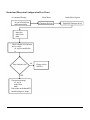
Kernel and Filesystem Configuration
The uClinux 2.0 kernel must have the digital I/O option compiled for proper operation. These options will be set
using the kernel configuration
cd /opt/uClinux/linux
make menuconfig
Using this main menu, under Character Devices the following must be selected
Digital IO Character Device
After saving your configuration changes, use the following commands in the same directory to complete
compilation of your kernel.
make clean
make dep
make
Now, check if the node for the digital I/O character device exists.
cd /opt/fs/romdisk/dev
If io1 exists in this directory, then continue to create the new image in the next step. If it does not exist, please
refer to Appendix A for further instructions.
Next a combined image of the new kernel and filesystem is to be created.
cd /opt/fs
make clean
make
Then use imagez.bin and run loader on the module to write in the filesystem and kernel. Please refer to the
User’s Manual for details on running loader. The dimmPCI module is now configured for digital I/O.
64
www.amctechcorp.com
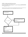
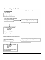
Kernel and Filesystem Configuration Flow Chart
At command Prompt
cd /opt/uClinux/linux
make menuconfig
Main Menu
Inside Menu Option
Character Devices
Digital IO Character device
make dep
make clean
make
Check if digital I/O character
device exists:
cd /opt/fs/romdisk/dev
ls
Does iolnode exist?
No
Please refer to
NOTE A
YES
Generate new image:
cd /opt/fs
make clean
make
Run loader on the dimmPCI
module using new image
www.amctechcorp.com
65
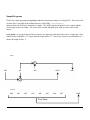
Available Digital I/O Pins
The number of pins available for digital I/O depends on the other options compiled into the kernel. For example,
if the EEPROM option is compiled in, then the bits from Port E bits[0-2] will not be available for digital I/O.
During boot up, devices that require pins for their dedicated functions will reserve them, and thus these pins
cannot be accessed by the digital I/O character driver. After all other drivers have reserved their required pins,
any remaining pins that have not been reserved will be used for digital I/O, and so a user-space program will be
able to access these pins via the character device.
In order for the pins to be reserved, a scan of applicable devices is done on boot up. Thus, the same kernel can
be used on any of the NETdimm, IOdimm, or CANdimm without having to recompile.
The pins are listed in Table 1 in their suggested order of use. The pins further down the list are more likely to
be used for their dedicated functions than those at the top. Table 1 also describes the respective port and bit
numbers of each class of pins, as well as their location on the backplane. Only the LCD class of I/O points and
Port G/pin5 lead to pin headers on the backplane. The remaining pins must be accessed by soldering wires to
the system or peripheral slot on the backplane. The following are notes regarding each class of pins.
The LCD class of pins are only used when an LCD display needs to be hooked up to the
dimmPCI module. Thus, they are the least likely to be used for their dedicated function, and
have the added advantage of leading to pin headers on the backplane.
The EEPROM class is only needed if an EEPROM is needed to store permanent information.
This device is normally not populated on the dimmPCI modules, making it unlikely that the
pins will be used for their dedicated function. Note that if the EEPROM is populated, those
pins cannot be used for digital I/O, even if the EEPROM driver has not been compiled in.
The SPI pins are used for peripheral interfaces such as an analog-to-digital converter. Note
that the IOdimm has its own driver for the SPI pins in order to take care of its I/O functions.
Thus, on an IOdimm the SPI pins will not be available for use by this digital I/O driver.
The ICE_DEBUG pins are the in-circuit debugger pins. These pins are more useful as
outputs, since they must not be held low on power up. PortG/Pin5 is the EMU break, and
access to this jumper pin is needed when running in rescue mode for ‘oops’. Also note that
PortG/Pin2 is the EMU IRQ, which is a non-maskable interrupt.
66
www.amctechcorp.com
Table 1: List of all available digital I/O pins
Class
Circuit N ame
Port
Bit
Backplane System Slot
LCD
LCD0
Port C
0
A18
LCD1
Port C
1
B18
LCD2
Port C
2
A17
LCD3
Port C
3
B17
LFRM
Port C
4
A15
LLP
Port C
5
B15
LCLK
Port C
6
A16
LADC
Port C
7
B16
LCO N TRAST
Port F
0
A14
EE MO SI
Port E
0
B13
EE MISO
Port E
1
B14
EE CLK
Port E
2
A13
SPI nIN T0
Port D
5
A24
SPI nIN T1
Port D
6
B23
SPI MO SI
Port J
0
B28
SPI MISO
Port J
1
A27
SPI CLK
Port J
2
A29
SPI nSS
Port J
3
B26
SPI nRDY
Port K
0
B27
SPI C S0
Port K
4
B24
SPI C S1
Port K
5
A25
SPI C S2
Port K
6
B25
SPI C S3
Port K
7
A26
EMU IRQ
Port G
2
B7
EMU PD
Port G
3
A7
EMU CS
Port G
4
B8
EMU BRK
Port G
5
A8
EEPRO M
SPI
ICE_DEBUG
www.amctechcorp.com
Backplane Header Pin
Pull- Up/ Pull- Down
Resistor
JP6, pin 9
Pull- Down
JP6, pin 10
Pull- Down
JP6, pin 11
Pull- Down
JP6, pin 12
Pull- Down
JP6, pin 2
Pull- Down
JP6, pin 3
Pull- Down
JP6, pin 4
Pull- Down
JP6, pin 1
Pull- Down
JP6, pin14
Pull- Up
Pull- Up
Pull- Up
Pull- Up
Pull- Up
Pull- Up
Pull- Up
Pull- Up
Pull- Up
Pull- Up
Pull- Up
Pull- Down
Pull- Down
Pull- Down
Pull- Down
Pull- Up
Pull- Up
Pull- Up
J7, pin 1
Pull- Up
67
Programming Structure
The structure that should be used to store pin configuration and information is dimm_io from dimmio.h,
located in /opt/uClinux/linux/include/linux/. Table 2 below describes the six fields of the
structure and their settings.
Table 2: dimm_io structure description
Field
68
Description
port_number
type - short
The port number corresponds to the ports of
the MC 68VZ328, where A = 0, B = 1, C =
2, … L = 11, M = 12
bit_number
type - short
The bit numbers are for each port, where 0 =
lsb, … 7 = msb
offset
type - long
This is the offset into the list of active pins.
The offset has a maximum range of 0 to 26.
mode
type - unsigned char
The mode determines the direction of the I/O
point, where 0 = input, 1 = output
state
type - unsigned char
The state describes the logic level on the pin,
where 0 = low, 1 = highN ote that the state
field is not updated when an ioctl call is used
and field exists only for programming
convenience.
pull_up_dn
type - unsigned char
The pull_up_dn controls the pull- up orpulldown register for each pin, where 0 =
disabled, 1 = enabled
www.amctechcorp.com
Digital I/O Functions
The low level functions used to manipulate the digital I/O points are the system calls open, lseek, read,
write, close, and ioctl. The uses of these functions are demonstrated in two simple sample programs,
xor.c and even_parity.c.
open gives access to the digital I/O character device. It takes two parameters, the node for your device in /
dev and the mode you wish to open it in. For the digital I/O device, you will want to use the node /dev/io1
and the mode for read and write O_RDWR. This function will return the handle to your device:
handle = open(“/dev/io1”, O_RDWR)
lseek will choose the current I/O point and takes three parameters including the handle, the offset, and a
descriptor for how the offset is used (SEEK_SET, SEEK_CUR, SEEK_END). SEEK_SET will position the
file pointer to an absolute position in the array of active pins as specified by the value in offset. SEEK_CUR will
move relative to the current position by the number in offset. SEEK_END will move the file pointer to the end
of the array of active pins. lseek should be used to position the file pointer prior to any read or write
operation.
lseek(handle, pin->offset, SEEK_SET)
read will read the value of the current I/O point. It takes three parameters, the handle, the byte(s) for the read
information to be stored to, and the number of bytes to be read. This function will only allow you to read from
the active pins. Reads can be done as a single pin or in a group of contiguous pins. The result of the read will
be 0xFF (high) or 0x00 (low). If the read operation was not successful, then an error will be returned. The
example below reads one byte into the state field of the dimm_io structure.
error = read(handle, &(pin->state), 1)
write sets the value of the current I/O point and it also takes three parameters, the handle, the byte(s) that will
be written to the output pins, and the number of bytes to be written. Note that only output pins can be written
to, and attempting to write to input pins will generate an error. Similar to reading, write operations can be done
for a single I/O point or as a contiguous group of pins. Write values are non-zero for high, and zero for low. The
example demonstrates writing one byte from the state field of the dimm_io structure. Prior to using this write
function, the state (0 or 1) of the pin was specified in the state field.
error = write(handle, &(pin->state), 1)
close will close the digital I/O device and only takes one parameter, the handle for the device. This should
be done once the device is no longer needed.
close(handle)
ioctl will configure an I/O point and it will pass control information to the device driver. Each ioctl call
takes three parameters, the handle, a descriptor of the desired command, and a pointer to a dimm_io structure:
error = ioctl(handle, DIMM_IO_IOCTL_SET_CONFIG_BY_PORT_BIT, pin)
Each of the command descriptors are listed below. If any of them are unsuccessful executing the function, an
error will return.
www.amctechcorp.com
69
DIMM_IO_IOCTL_MAP will return an offset given a port and bit number. The bit and port
number must be assigned to port_number and bit_number in the dimm_io structure that is passed to the ioctl command. The offset will be assigned to the offset field of
the structure if the port and bit number exists in the list of active I/O points, otherwise an
error is returned.
DIMM_IO_IOCTL_RETRIEVE returns a port and bit number given an offset. The offset
must be assigned to the dimm_io structure passed to the ioctl call. As long as the
offset is smaller than the maximum number of active pins, the port and bit numbers in the
structure will be set. If the offset does not correspond to an active I/O point, then an error
will be returned.
DIMM_IO_IOCTL_SET_CONFIG_BY_OFFSET will set the necessary registers to configure the I/O point specified by the offset. Thus, the fields for offset, mode, and
pull_up_dn must be set. After the function call, the pin will be configured according to
those settings, and the device driver will fill in the corresponding port_number and
bit_number in the structure.
DIMM_IO_IOCTL_SET_CONFIG_BY_PORT_BIT will also configure the I/O point,
but as specified by the port and bit number in the dimm_io structure. Similar to the
configuration by offset, the mode, and pull_up_dn must be set. After returning successfully from the ioctl call, the offset for the port and bit number will also be set.
DIMM_IO_IOCTL_GET_CONFIG_BY_OFFSET will retrieve the configuration of the I/
O point specified by the offset. After successful execution, the fields port_number,
bit_number, mode, and pull_up_dn will be set with their appropriate information.
DIMM_IO_IOCTL_GET_CONFIG_BY_PORT_BIT will get the settings of the I/O point
specified by the port_number and bit_number. Upon returning from the ioctl
call, the offset, mode, and pull_up_dn will reflect the hardware settings.
70
www.amctechcorp.com
Sample Programs
Each of the sample programs even_parity.c and xor.c demonstrate simple use of digital I/O. The source code
for these files is available in the samples directory of the SDK, /opt/samples.
xor.c performs the XOR logic function on 3 inputs. The XOR is performed on the first two inputs and the
result output to the first output. The result of the second and third input XOR are sent to the second
output.
even_parity.c is a program that will do even parity on 8 input pins, and the result is sent to 1 output pin. Thus,
if there is an even number of ‘1’ inputs, then the output will be ‘0’. Conversely, if there is an odd number of ‘1’
inputs, the output will be ‘1’.
xor.c
in0
in1
in2
out0
out1
even.c
in0
in1
in2
in3
in4
in5
in6
in7
out0
Even Parity
www.amctechcorp.com
71
NOTE A: Creating a node for the character device
Since the node for the digital I/O device does not exist in the /opt/fs/romdisk/dev directory, it needs to
be created. Create the node by doing the following as root, where 123 is the major number and 1 the minor
number of the character device io1.
mknod io1 c 123 1
After the correct node is created, then continue with compiling the kernel and filesystem image. Below is the
modified flowchart including the extra step of creating the digital I/O character device node.
Check if digital I/O character device exists:
cd /opt/fs/romdisk/dev
ls
NO
Does io1 node exist?
In the current /opt/fs/romdisk/dev
directory, create the digital I/O character
device node:
mknod io1 c 123 1
YES
Generate new image:
cd /opt/fs/
make clean
make
Run loader on the dimmPCI module
using the new image
72
www.amctechcorp.com
www.amctechcorp.com
73
This page left intentionally blank
74
www.amctechcorp.com
D2
Application Note 2
Configuring dimmPCI Modules for Communication
April 21, 2003
Version 0.1
Authors: Bernice Lau, Robert Austen
Abstract
On a dimmPCI backplane, there are several possible slots in which a dimmPCI may be inserted, the system slot
or the peripheral slots. With the correct options compiled into the kernel and system configuration, the two
modules can be set up to communicate with each other. The communication is achieved using the PCI I2O
transport layer to send ethernet packets over the PCI bus to another likewise configured module.
Introduction
In order to connect the two dimmPCI modules, it is necessary to set up the hardware as a subnet. A NETdimm
must be in the system slot to interface to the local network through the ethernet port.
Local Network
Outside
Network
dimmPCI Subnet 192.168.7.0
Gateway
out
Peripheral Slot
dimmPCI module
System Slot
NETdimm
192.168.10.1
GW out
eth
192.168.10.5
GW in
192.168.7.1
eth0
pci0
PCI
pci0
192.168.10.87
192.168.10. 37
outside
interface
www.amctechcorp.com
192.168.7.2
inside
interface
75
On the NETdimm in the system slot, the ethernet port, eth0, must be configured to have an IP address on the
local network for your host computer. Therefore eth0 acts as a gateway into the dimmPCI subnet for the local
area network. It is also the outside interface for your subnet to the local area network.
On the system slot NETdimm, the pci0 device is the inside interface to a second or third dimmPCI module in a
peripheral slot. This device will be the gateway used by each peripheral dimmPCI module.
On the peripheral dimmPCI module, only the pci0 interface needs to be configured. This device must be set up
to communicate with the pci0 device on the system slot NETdimm.
Requirements
•
•
•
•
dimmPCI passive backplane 1.1
NETdimm 1.2 or higher for system slot on dimmPCI backplane
NETdimm 1.3 or higher, or IOdimm or CANdimm for peripheral slot
2.0.38 or higher kernel source and filesystem (SDK 2.03 or higher)
Note: When two NETdimm units are used on the backplane, the system slot device will cause the peripheral
device to reset as well. A NETdimm 1.3 is required since NETdimm 1.2 in the peripheral slot will not wait for the
system slot device on reset and will not get initialised.
The following files and programs will be used:
rc
imagez.bin
loader
Kernel Configuration
The 2.0 kernel must have specific networking and PCI options included in order for communication to occur
between two dimmPCI modules. These options will be set using the kernel configuration
cd /opt/uClinux/linux
make menuconfig
Using this main menu, under General Setup the following must be selected:
PCI support
PCI I2O transport layer
PCI networking support
The following default values for some PCI settings are already fairly optimal in the General Setup menu. It is
essential that the PCI frame size be the same for both dimmPCI devices if the default values are not used, since
the PCI frame size will set the maximum transmission unit (MTU) size.
5 PCI receive frames
2 PCI transmit frames
4 PCI frame size
76
www.amctechcorp.com
From the main menu, inside of Networking Options this option must be set:
IP forwarding/gatewaying
Again, from the main menu under Network device support:
Network device support
NE2000/NE1000 ISA ethernet
After saving your configuration changes, use the following commands in the same directory to complete
compilation of your kernel.
make clean
make dep
make
www.amctechcorp.com
77
Kernel Configuration Flow Chart
At Command Prompt
cd /opt/uClinux/linux
make menuconfig
Main Menu Option
General Setup
PCI support
PCI I2O transport layer
PCI networking support
Networking
Options
IP forwarding/gatewaying
Networking
device support
make clean
make dep
make
78
Options to Select
www.amctechcorp.com
Network device support
NE2000/NE1000 ISA ethernet
Filesystem Configuration
For the dimmPCI units to be correctly configured for the subnet, the rc file must be modified. These different
configurations should each be contained in a separate copy of the filesystem, since different applications will
be used. Copies of the filesystem can be generated in the following way. Here we will assume that the original
filesystem is /opt/newfs, and the new filesystems, sysfs is for the system slot and perfs for the peripheral
slot.
cd /opt/
cp –Rpdx newfs sysfs
cp –Rpdx newfs perfs
where R, copy directories recursively
p, preserve file attributes if possible
d, never follow symbolic links
x, stay in this filesystem
For both the system slot and peripheral slot dimmPCI modules, the ‘dhcp’ client must be turned off, which can
be done by commenting it out with ‘#’ in front of the line. This must be done since the IP addresses and routes
are set statically.
The following code should be added to the system slot rc file to set the IP information. The rc file is located in
/opt/sysfs/romdisk/etc/, where sysfs is the name of filesystem for the system slot.
# attach the pci0 and eth0
/sbin/ifattach —addr 192.168.10.87 —net 192.168.10.0 —mask \
255.255.255.0 —gw 192.168.10.1 eth0
/sbin/ifattach —addr 192.168.7.1 —net 192.168.7.0 –mask \
255.255.255.0 pci0
eth0 will be set up as a device on the local network, so its address must be on the local network. Here, the local
network is on 192.168.10.0 and the IP address has been set specifically to 192.168.10.87. The gateway 192.168.10.1
specifies the machine that acts as an interface between the local network and the outside network, and will be
redirecting information from the local network to the subnet you are creating with the two dimmPCI modules.
pci0 will be a device on the PCI subnet, here set as 192.168.7.0 and its IP address is set accordingly as
192.168.7.1.
Note that the ‘\’ character at the end of the lines indicated that the command continues on the next line.
For the peripheral slot dimmPCI module, pci0 is the only network interface; there is no physical ethernet
connection for the peripheral module to set up. This is the code that must be added to a peripheral slot rc file
in /opt/perfs/romdisk/etc/.
# attach the pci0
/sbin/ifattach —addr 192.168.7.2 —net 192.168.7.0 \
—mask 255.255.255.0 —gw 192.168.7.1 pci0
pci0 is on the subnet (192.168.7.0), and has an IP address of 192.168.7.2. The subnet for the pci0 devices on
both modules must be the same. For the peripheral module, a gateway must be
www.amctechcorp.com
79
specified since pci0 will be the network interface. The gateway value must correspond to the IP address of the
system slot pci0, 192.168.7.1.
Thus, different rc files must be configured for each copy of the filesystem, generating a different image to be
loaded for each module. Note that the eth0 and pci0 can be configured manually by typing in the specific
information at the command prompt on the dimmPCI module, but changes will not be retained upon reboot.
Create a combined image of the new kernel and modified filesystem.
cd /opt/<filesystem name>
make clean
make
Then use imagez.bin and run loader on the module to write in the modified filesystem and kernel. Please refer
to the User’s Manual for details on running loader. The dimmPCI module is now configured for communication
with another device.
To streamline development, part of the computer’s hard drive can be made available using NFS. These changes
will occur in the rc file.
80
www.amctechcorp.com
Filesystem Configuration Flow Chart
Modifications to ‘rc’ file
At Command Prompt
Copy filesystem
cd /opt/
cp –Rpdx newfs sysfs
cp –Rpdx newfs perfs
System Slot NETdimm Configuration
comment out ‘dhcp’ client line (if applicable)
add static ip code for eth0 and pci0
save changes & exit
cd /opt/sysfs/romdisk/etc/
vi rc
Generate new system slot image:
cd /opt/sysfs/
make clean
make
Run loader on the NETdimm
using the new image
Peripheral Slot dimmPCI module Configuration
cd /opt/perfs/romdisk/etc/
vi rc
comment out ‘dhcp’ client line (if applicable)
add static ip code for pci0
save changes & exit
Generate new peripheral slot image:
cd /opt/perfs/
make clean
make
Run loader on the dimmPCI module
using the new image
www.amctechcorp.com
81
Host machine Configuration
After configuring the two dimmPCI modules, they can now communicate with each other, as well as the
outside network. But the outside network cannot access the dimmPCI subnet. Therefore a route to the
subnet must be added to redirect packets to the proper device. The most convenient method is to add the
route to the gateway for the local network, in this example it is 192.168.10.1. On the machine that acts as the
gateway, the following command would be used at the command line
route add –net 192.168.7.0 netmask 255.255.255.0 gw 192.168.10.87
net specifies the subnet that you wish to add the route to and gw is the gateway into the dimmPCI subnet, the
eth0 IP address on the system slot NETdimm.
Testing
To test if the configuration was successful and the network was established, execute the following commands.
On the host machine:
ping 192.168.10.87
ping 192.168.7.2
telnet 192.168.7.2
(this tests the system slot NETdimm configuration)
(this tests the peripheral slot dimmPCI module configuration)
(this gives you access to the peripheral slot dimmPCI module)
In the telnet session for the peripheral slot dimmPCI module:
ping <host machine ip address>
82
www.amctechcorp.com
(this indicates that the peripheral slot
dimmPCI module has access to the outside
network)
www.amctechcorp.com
83
This page left intentionally blank
84
www.amctechcorp.com
D3
Application Note 4
Using Multiple NETdimm Modules
Author: Bernice Lau
Version 0.1
Abstract
On a dimmPCI backplane, there are several possible slots in which a dimmPCI may be inserted, the
system slot or the peripheral slots. Once configuration has been completed, the NETdimm modules can
successfully communicate with each other. This application note describes the use of the PCI bus sending
ethernet packets to transfer a file between two NETdimm devices.
Introduction
After configuration of the NETdimm modules has been completed, they can communicate with each
other in an ethernet fashion. Two variants of a simple file transfer program have been developed to demonstrate this ability.
The programs server.c and client.c can run once configuration is done. The programs inetServer.c and
inetClient.c require modifications to /etc/services and /etc/inetd.conf since they interface with
inetd. All the programs employ networking sockets in order to communicate.
Requirements
• dimmPCI backplane 1.1
• NETdimm 1.2 or higher for system slot on dimmPCI backplane
• NETdimm 1.3 for peripheral slot
• 2.0.38 or higher kernel source and filesystem (SDK 2.05 or higher)
• sample programs in SDK, /opt/user_code/networking/filetransfer
o client.c
o server.c
o inetClient.c
o inetServer.c
Note: When two NETdimm units are used on the backplane, the system slot device will cause the peripheral
device to reset as well. A NETdimm 1.3 is required since NETdimm 1.2 in the peripheral slot will not wait for the
system slot device on reset and will not get initialised.
Configuration of the NETdimm modules must be completed beforehand, please refer to the application note
‘Configuring dimmPCI Modules for Communication for Kernel v.2.0’.
www.amctechcorp.com
85
Simple Server & Client
The sample programs server.c and client.c are available in the SDK samples directory,
/opt/user_code/networking/filetransfer/without_inetd. The programs interact using
Internet sockets, AF_INET. Once the sockets have been established they can be read from and written to in
order to transfer information. Each program will be run on a separate NETdimm, and using the IP addresses
established during configuration, text files such as hello.txt can be transferred between them.
The server will set up its own socket and wait for an incoming client socket. Upon accepting a client connection, it will set up a client socket, and go through a series of read and write operations on the socket to accept
the file transfer.
On the client side, it will set up a socket and then attempt to connect to a server. Once a connection has been
established the socket will be used for reads and writes to the server to transfer the file.
Note that the port that the client and server sockets will connect through must be the same. It has been hard
coded in the program during the socket setups.
Inetd based Server & Client
The sample programs inetServer.c and inetClient.c are available in the SDK samples directory,
/opt/user_code/networking/filetransfer/with_inetd. These programs interact through
the internet daemon, inetd. Similar to the simple server and client programs, a text file can be transferred
between two NETdimms using the IP addresses established during configuration.
The following instructions must be added to the config files of the root file system of both NETdimm modules
for the inet based server and client to work. In /etc/services the service that needs to be called,
inetServer, must be added to the list in the format
service-name
port/protocol
eg.
inetServer 9735/tcp
The port number can be chosen arbitrarily, so long as it does not already exist in the services list and is not
below 1024, which are reserved for system use.
In /etc/inetd.conf the program and path that inetd will load must be added in the format
service-name endpoint-type protocol wait-status uid server-program serverarguments
eg.
inetServer stream tcp nowait root /usr/inetServer
The server side of the program is started by inetd, allowing the read and write operations to go to standard
input and output. inetd will listen on all service ports for the services listed in
86
www.amctechcorp.com
inetd.conf. Upon receiving a connection request, it will start up the server. Therefore the server has no need
to set up sockets.
The inetClient is very similar to the simple client, since it must still read and write to a socket. The socket is set
up using information gathered by the function getservbyname() which will check for the service inetServer on
the host NETdimm. After confirmation of the service is established, the program will create a socket, connect
and transfer the file as before. Unlike the simple client, there is no need to designate the connection port since
getservbyname() will retrieve this information.
www.amctechcorp.com
87
This page left intentionally blank
88
www.amctechcorp.com
D4
Application Note 5
Using Analog and Digital I/O with the
IOdimm
June 30, 2003
Version 0.1
Author: Bernice Lau
Introduction
The IOdimm is designed to support dedicated analog and digital I/O. There are 8 analog inputs, 2 analog
outputs, 8 digital inputs and 4 digital outputs. All of these I/O channels are accessible from the dimmPCI
backplane. User-space programs interact with the I/O channels through a device driver using standard system
calls.
Requirements
•
•
•
•
dimmPCI passive backplane
IOdimm 2.0 or higher
SDK 2.05 or higher (2.0.38 or higher kernel source and filesystem)
sample programs in SDK /opt/samples/card_specific/iodimm
o fir.c
o xor_iodimm.c
o even_parity_iodimm.c
Kernel and Filesystem Configuration
The uClinux 2.0 kernel must have the IOdimm SPI option compiled for proper operation. These options will be
set using the kernel configuration
cd /opt/uClinux/linux
make menuconfig
Using this main menu, under Platform dependent setup the following options must be selected
SPI support for IOdimm
ADC MAX1203
www.amctechcorp.com
89
After saving your configuration changes, use the following commands in the same directory to complete
compilation of your kernel.
make clean
make dep
make
Next make a copy of the filesystem, specifically for the IOdimm
cd /opt/
cp –Rpdx newfs iodimmmfs
Then create a combined image of the new kernel and filesystem.
cd /opt/iodimmfs
make clean
make
Finally use imagez.bin and run loader on the IOdimm to write in the filesystem and kernel. Please refer to the
User’s Manual for details on running loader. The IOdimm is now configured for its I/O operations.
90
www.amctechcorp.com
Kernel and Filesystem Configuration Flow Chart
At Command Prompt
Main Menu
Inside Menu Option
cd /opt/uClinux/linux
make menuconfig
Platform dependent support
SPI support for IOdimm
ADC MAX1203
make dep
make clean
make
Make a copy of the filesystem:
cd /opt/
cp –Rpdx newfs iodimmfs
Generate new image:
cd /opt/iodimmfs/
make clean
make
Run loader on the IOdimm
using the new image
www.amctechcorp.com
91
Available I/O Pins
The IOdimm has 8 analog inputs, 2 analog outputs, 8 digital inputs, and 4 digital outputs available for use. Note
that only the analog I/O channels lead to headers on the backplane. Any digital I/O channels must be accessed
by soldering wires to the peripheral slot where the IOdimm is inserted.
Table 1: List of all available I/O pins
Category
Channel
Analog Input
Analog
Output
Digital Input
Digital
Output
92
0
1
2
3
4
5
6
7
0
Backplane System
Slot
A1
B1
A2
B2
A5
B5
A7
B7
A9
Backplane Header
Pin
JP1/1
JP2/1
JP1/2
JP2/2
JP1/5
JP2/5
JP1/7
JP2/7
JP1/9
1
0
1
2
3
4
5
6
7
0
B9
A15
B15
A16
B16
A17
B17
A18
B18
A19
JP2/9
JP1/15
JP2/15
JP1/16
JP2/16
JP1/17
JP2/17
JP1/18
JP2/18
1
2
3
B19
A20
B20
www.amctechcorp.com
I/O Functions
The low level functions used to manipulate the I/O channels are the system calls open, lseek, read,
write, close, and ioctl. The I/O channels are accessed through 3 character drivers for the digital I/O,
ADC, and DAC. The uses of these functions are demonstrated in the sample programs fir.c, xor_iodimm.c, and
even_parity_iodimm.c.
Digital Inputs and Outputs
For the digital input and output pins, each channel corresponds to one byte, where channel 0 is the 0th byte,
channel 1 is the 1st byte, etc. The device can be accessed by a handle to the node /dev/io0 for both read and
write. When writing to the pin, 0 will be low (0V) and non-0 will be high (as shipped, 12V, or if strapped, VIO).
When reading a pin, the driver will read back 0 for a low signal, and 255 for a high signal. lseek should be
used to position the file pointer for access to I/O channels. There are 8 digital inputs and 4 digital outputs, so
channels [0-3] can be written to and read from, but channels [4-7] can only be read.
Specific to the digital outputs, there are ioctl calls to pass control information to the device driver. Each
ioctl call takes three parameters, the handle, a descriptor of the desired command, and an integer, though in
some cases the integer is ignored.
result=ioctl(handle, PIC_SETUP0, PIC_SETUP_PUSH_PULL)
Each of the command descriptors are listed below. If any of them are unsuccessful executing the function,
an error will return. Please note that the PWM channels are currently not supported. Both PWM0 and
PWM1 cannot be used at the same time since PWM0 is connected to the low-side driver and PWM1 is
connected to the high-side driver.
DAC_POWER_DOWN should be used to power down the DAC once it is no longer needed.
Note that the argument is ignored for this ioctl call.
PIC_SETUP0, PIC_SETUP1, PIC_SETUP2, PIC_SETUP3 will configure each digital
out channel according to the integer specified in the argument. Each of the argument values
are described below.
PIC_SETUP_LO_SIDE will configure an output pin as a low-side driver.
PIC_SETUP_HI_SIDE will configure an output pin as a high-side driver.
PIC_SETUP_PUSH_PULL will configure an output pin as a push-pull output.
PIC_SETUP_HI_Z will configure an output pin into a high impedance state.
Analog I/O
For both the ADC and the DAC, each channel corresponds to 2 bytes, such that channel 0 is the 0th and 1st
bytes, channel 1 is the 2nd and 3rd bytes, etc. The data in the bytes is binary encoded, in little endian format
where the least significant bit is at the lower offset in the file. Values that can be written or read from the
channels are unipolar from 0 to 4095, corresponding to 0 to 4.095V, thus there is 1mV per count. lseek
should be used to move around the file to access I/O channels. For both reads and writes, as few as 1 or as
many as all analog I/O channels can be accessed at once.
www.amctechcorp.com
93
As shipped, each ADC channel has a divide by 4 attenuator stage and a multiply by 2 amplifier stage. Thus for
a signal applied to analog input pins on the backplane, a count of 4095 will correspond to a voltage of 8.192V.
For the DAC, analog output 0 has a multiply by 2 gain stage, so a count of 4095 corresponds to a voltage of
8.192V. Analog output 1 has a 4-20 current output circuit, with a count of 0 corresponding to approximately
3.5mA and 4095 corresponding to about 25mA.
Sample Programs
The sample program fir.c demonstrates the use of the ADC and DAC of the IOdimm. The digital I/O functions
are demonstrated by the sample programs xor_iodimm.c and even_parity_iodimm.c.
fir.c will read analog input from a channel on the ADC. This input will be fed into a FIR filter, and then the output
is written to the DAC. The source code for fir.c is available in /opt/samples/card_specific/
iodimm/fir.
There are 29 coefficients h(k) used to calculate the digital output values, y(n), given the digitised input x(n)
using the summation
28
y (n ) = ∑ h(k ) ∗ x(n − k )
k =0
The filter is prototyped using a Hamming window given N=29, the finite impulse response given by:
h(n ) =
sin (0.33π (n − 14 ))
n
∗ 0.54 − 0.46 cos 2π
π (n − 14 )
28
Note that:
sin (kx )
≈k
x →0
x
lim
as shown by the Taylor expansion of sine
x3 x5 x7
sin ( x ) ≈ x −
+
−
+Κ
3! 5! 7!
3
5
7
sin (kx ) kx (kx )
(
(
kx )
kx )
≈
−
+
−
+Κ
x
x x ∗ 3! x ∗ 5! x ∗ 7!
94
www.amctechcorp.com
The sample FIR is a quick and dirty low pass filter with linear phase. The design parameters of the filter are a
–3dB cutoff at Ωc = 30π rad/sec, ωc = 0.3π rad and an attenuation of 50dB at Ωr = 45π rad/sec, ωr = 0.45π
rad. For example, a sampling rate of 64000 samples/second (T-1 = 64000 samples/s), yields a analog
frequency cutoff of 9.6kHz and the 50dB attenuation corner point at 14.4kHz.
xor_iodimm.c performs the XOR logic function on 3 inputs. The XOR is performed on the first two inputs
and the result output to the first output. The result of the second and third input XOR are sent to the
second output. The source code for xor_iodimm.c is available in /opt/samples/card_specific/
iodimm/dio.
in0
in1
in2
www.amctechcorp.com
out0
out1
95
even_parity_iodimm.c is a program that will do even parity on 8 input pins, and the result is sent to 1 output
pin. Thus, if there is an even number of ‘1’ inputs, then the output will be ‘0’. Conversely, if there is an odd
number of ‘1’ inputs, the output will be ‘1’. The source code for xor_iodimm.c is available in /opt/
samples/card_specific/iodimm/dio.
in0
in1
in2
in3
in4
in5
Even Parity
96
www.amctechcorp.com
in6
in7
out0
www.amctechcorp.com
97
This page left intentionally blank
98
www.amctechcorp.com
D5
Oops Documentation
Using Oops
June 11, 2003
Version 0.1
Authors: Bernice Lau, Robert Austen
Introduction
oops is a program to upload/download to a M68K family processor using EMU mode.
The executable must be compiled for the first time using gcc on the development platform. There is a Makefile
included in
/opt/boottools/oops/src
Prior to running ‘oops’ the jumper must be inserted on EMU BREAK and the dimmPCI board reset. Any terminal
software (minicom, etc.) that may be using the serial port must be closed. oops can be invoked from the
directory /opt/boottools/oops using
./oops
After ‘oops’ has finished running, the jumper on EMU BREAK must be removed and then the dimmPCI board
resets to boot a new kernel.
Purpose & basic format of files for oops
init.b contains the initialisation sequence for the Dragonball VZ. The file is a Motorola b-record for the
processor, and init.b is the default initialisation file. It is the first file to be transferred using oops. (See the
appendix for more information on init.b)
xloader.bin is a binary file that is the default upload program file. This program will write and verify the flash. It
is the second file to be transferred. Once it has been sent, it will start running and will participate in receiving the
target image.
loader.bin is a binary file that will also write and verify the flash. This program will not start until the target image
has been loaded into RAM.
www.amctechcorp.com
99
kernel.bin is a binary file containing the image of the compiled dimmPCI kernel, and it is the default kernel file.
kernel.bin is in the current working directory, but it is a symbolic link to a stable kernel image with a descriptive
but lengthy file name.
image.bin is a binary file set as the default download program file, which will make an image of an area of the
Dragonball memory, most likely flash.
memory.bin is a binary file to download an image of the memory.
Upload & Flash
There are two mode types in which ‘oops’ can operate in order to upload & flash an image.
Type 1
sends init.b
sends flash programmer type 1 (loader.bin)
sends image (in b-record format)
run flash programmer
capture output
Type 2 (default)
sends init.b
sends flash programmer type 2 (xloader.bin)
runs flash programmer
sends image (in binary format)
captures output
In Type 2, the image is sent in binary using xloader.bin to receive 4K blocks at a time, which is faster. With Type
1, the image must first be converted to b-records prior to sending. The mode of upload & flash can be changed
as follows:
-lp or -up <flash programmer type 1>
-xp
<flash programmer type 2>
If oops is run without arguments, then it will run by default in Type 2 mode.
To specify the image to be uploaded:
-k <image>
The default image file to be uploaded is kernel.bin.
Prior to writing to the flash, the flash memory will be erased. There are two different methods of erasing.
-ec
erases the entire flash before writing (default)
-em
erases the flash as required in ’64K blocks’
100
www.amctechcorp.com
Erasing the flash with the -em option allows for the journaling flash file system (jffs) to be preserved when you
wish to load a new image consisting of the kernel and root filesystem.
————————————————————
| kernel | rootfilesystem | <blank> | jffs
|
————————————————————
<—— replaced ——>
<—saved—>
After the image has been written to flash, the system will reset. There are two reset modes:
auto-reset (default):
-ra
manual reset, waits for user input: -rm
Upload & Run
oops will follow the following process to upload & run:
send init.b
send program
start program
capture output
To specify the image to be uploaded:
-k <image>
This will load the image at the start of flash, address 0.
To start a kernel, or other object, already in flash:
-sk <absolute start address>
For upload & run, if both -k and -sk are used in conjunction, an object can be downloaded to location 0 and
start execution at an arbitrary location. For example, a kernel could be compiled to run in RAM, loaded and then
run.
Download
oops will follow the following process to download:
send init.b
send program
start program
capture output
Most often, the capture file option will be used in this process.
www.amctechcorp.com
101
To download using the default download program, image.bin:
-d
This will download an image from the flash.
To specify the download program:
-dp <download program>
Two binaries have been provided for this purpose, image.bin and memory.bin. image.bin as mentioned above
is the default, while memory.bin will download an image of the memory.
The start and length of the image desired for download can be specified:
-dr <start, length>
eg. If you have 1Mbyte flash, and you wish to download 4 sectors of the jffs, then the start address
and length would be specified by:
-dr 0xC0000 0x40000
The start address specified here is relative to the start of the flash.
The addressing mode can also be changed with the following options:
relative to flash, start is 0x0 (default mode): -df
absolute addresses:
-da
After obtaining the captured output, it can be fed into the conv utility to convert the output file to binary. The
source code for the utility is located in /opt/boottools/oops/src/conv.
Common oops program arguments
Verbose output mode: -v
Quiet operation mode (default): -q
To select a serial port (default is ‘/dev/ttyS0’): -p <serialPortName>
Change to fast serial port, 230.4kbps (default is 115kbps): -pf
Select initialisation program file(default is init.b): -ip <initFilename>
Select a capture output file: -c <captureFilename>
By default, there is no capture file specified, and all information will go to standard output. When capturing the
output, if the file already exists, then the new information will be appended to the end of the file, not erase the
current contents.
102
www.amctechcorp.com
Appendix
The following is the format of the init.b file:
aaaaaaaaccdd’\n\r’
where
aaaaaaaa
address
cc
count (cannot be equal to 0)
dd
<cc> number of bytes
eg. cc=2, there must be dddd = 2 dd
‘\n\r’
each line is followed by a carriage return and/or line feed
WAIT <n>
# ———
causes a wait for <n> ms
comment
www.amctechcorp.com
103
This page left intentionally blank
104
www.amctechcorp.com
E
Appendix
Licensing, Copyrights & Liability
dimmPCITM Software Development Kit Distribution
The different parts of the distribution are licensed under various OpenSource License agreements. Ensure that you examine the code in question for the appropriateness of its license to a
given applications. Some of the licenses used are reproduced in this section for your reference.
GNU GENERAL PUBLIC LICENSE
Version 2, June 1991
Copyright (C) 1989, 1991 Free Software Foundation, Inc.
675 Mass Ave, Cambridge, MA 02139, USA
Everyone is permitted to copy and distribute verbatim copies of this license document, but
changing it is not allowed.
Preamble
The licenses for most software are designed to take away your freedom to share and change it.
By contrast, the GNU General Public License is intended to guarantee your freedom to share and
change free software—to make sure the software is free for all its users. This General Public
License applies to most of the Free Software Foundation’s software and to any other program
whose authors commit to using it. (Some other Free Software Foundation software is covered by
the GNU Library General Public License instead.) You can apply it to your programs, too.
When we speak of free software, we are referring to freedom, not price. Our General Public
Licenses are designed to make sure that you have the freedom to distribute copies of free
software (and charge for this service if you wish), that you receive source code or can get it if
you want it, that you can change the software or use pieces of it in new free programs; and that
you know you can do these things.
To protect your rights, we need to make restrictions that forbid anyone to deny you these rights
or to ask you to surrender the rights. These restrictions translate to certain responsibilities for
you if you distribute copies of the software, or if you modify it.
www.amctechcorp.com
105
For example, if you distribute copies of such a program, whether gratis or for a fee, you must give
the recipients all the rights that you have. You must make sure that they, too, receive or can get
the source code. And you must show them these terms so they know their rights.
We protect your rights with two steps: (1) copyright the software, and (2) offer you this license
which gives you legal permission to copy, distribute and/or modify the software.
Also, for each author’s protection and ours, we want to make certain that everyone understands
that there is no warranty for this free software. If the software is modified by someone else and
passed on, we want its recipients to know that what they have is not the original, so that any
problems introduced by others will not reflect on the original authors’ reputations.
Finally, any free program is threatened constantly by software patents. We wish to avoid the
danger that redistributors of a free program will individually obtain patent licenses, in effect
making the program proprietary. To prevent this, we have made it clear that any patent must be
licensed for everyone’s free use or not licensed at all.
The precise terms and conditions for copying, distribution and modification follow.
GNU GENERAL PUBLIC LICENSE
TERMS AND CONDITIONS FOR COPYING, DISTRIBUTION AND MODIFICATION
0. This License applies to any program or other work which contains a notice placed by the
copyright holder saying it may be distributed under the terms of this General Public License.
The “Program”, below, refers to any such program or work, and a “work based on the Program”
means either the Program or any derivative work under copyright law: that is to say, a work
containing the Program or a portion of it, either verbatim or with modifications and/or translated
into another language. (Hereinafter, translation is included without limitation in the term “modification”.) Each licensee is addressed as “you”.
Activities other than copying, distribution and modification are not covered by this License;
they are outside its scope. The act of running the Program is not restricted, and the output from
the Program is covered only if its contents constitute a work based on the Program (independent
of having been made by running the Program). Whether that is true depends on what the
Program does.
1. You may copy and distribute verbatim copies of the Program’s source code as you receive it,
in any medium, provided that you conspicuously and appropriately publish on each copy an
appropriate copyright notice and disclaimer of warranty; keep intact all the notices that refer to
this License and to the absence of any warranty; and give any other recipients of the Program a
copy of this License along with the Program.
106
www.amctechcorp.com
You may charge a fee for the physical act of transferring a copy, and you may at your option
offer warranty protection in exchange for a fee.
2. You may modify your copy or copies of the Program or any portion of it, thus forming a work
based on the Program, and copy and distribute such modifications or work under the terms of
Section 1 above, provided that you also meet all of these conditions:
a) You must cause the modified files to carry prominent notices stating that you changed the
files and the date of any change.
b) You must cause any work that you distribute or publish, that in whole or in part contains or is
derived from the Program or any part thereof, to be licensed as a whole at no charge to all third
parties under the terms of this License.
c) If the modified program normally reads commands interactively when run, you must cause it,
when started running for such interactive use in the most ordinary way, to print or display an
announcement including an appropriate copyright notice and a notice that there is no warranty
(or else, saying that you provide a warranty) and that users may redistribute the program under
these conditions, and telling the user how to view a copy of this License. (Exception: if the
Program itself is interactive but does not normally print such an announcement, your work based
on the Program is not required to print an announcement.)
These requirements apply to the modified work as a whole. If identifiable sections of that work
are not derived from the Program, and can be reasonably considered independent and separate
works in themselves, then this License, and its terms, do not apply to those sections when you
distribute them as separate works. But when you distribute the same sections as part of a whole
which is a work based on the Program, the distribution of the whole must be on the terms of this
License, whose permissions for other licensees extend to the entire whole, and thus to each and
every part regardless of who wrote it.
Thus, it is not the intent of this section to claim rights or contest your rights to work written
entirely by you; rather, the intent is to exercise the right to control the distribution of derivative
or collective works based on the Program.
In addition, mere aggregation of another work not based on the Program with the Program (or
with a work based on the Program) on a volume of a storage or distribution medium does not
bring the other work under the scope of this License.
3. You may copy and distribute the Program (or a work based on it, under Section 2) in object
code or executable form under the terms of Sections 1 and 2 above provided that you also do
one of the following:
www.amctechcorp.com
107
a) Accompany it with the complete corresponding machine-readable source code, which must be
distributed under the terms of Sections 1 and 2 above on a medium customarily used for software
interchange; or,
b) Accompany it with a written offer, valid for at least three years, to give any third party, for a
charge no more than your cost of physically performing source distribution, a complete machinereadable copy of the corresponding source code, to be distributed under the terms of Sections 1
and 2 above on a medium customarily used for software interchange; or,
c) Accompany it with the information you received as to the offer to distribute corresponding
source code. (This alternative is allowed only for noncommercial distribution and only if you
received the program in object code or executable form with such an offer, in accord with Subsection b above.)
The source code for a work means the preferred form of the work for making modifications to it.
For an executable work, complete source code means all the source code for all modules it
contains, plus any associated interface definition files, plus the scripts used to control compilation and installation of the executable. However, as a special exception, the source code distributed need not include anything that is normally distributed (in either source or binary form) with
the major components (compiler, kernel, and so on) of the operating system on which the
executable runs, unless that component itself accompanies the executable.
If distribution of executable or object code is made by offering access to copy from a designated
place, then offering equivalent access to copy the source code from the same place counts as
distribution of the source code, even though third parties are not compelled to copy the source
along with the object code.
4. You may not copy, modify, sublicense, or distribute the Program except as expressly provided
under this License. Any attempt otherwise to copy, modify, sublicense or distribute the Program
is
void, and will automatically terminate your rights under this License. However, parties who have
received copies, or rights, from you under this License will not have their licenses terminated so
long as such parties remain in full compliance.
5. You are not required to accept this License, since you have not signed it. However, nothing
else grants you permission to modify or distribute the Program or its derivative works. These
actions are prohibited by law if you do not accept this License. Therefore, by modifying or
distributing the Program (or any work based on the Program), you indicate your acceptance of
this License to do so, and all its terms and conditions for copying, distributing or modifying the
Program or works based on it.
108
www.amctechcorp.com
6. Each time you redistribute the Program (or any work based on the Program), the recipient
automatically receives a license from the original licensor to copy, distribute or modify the
Program subject to these terms and conditions. You may not impose any further restrictions on
the recipients’ exercise of the rights granted herein. You are not responsible for enforcing
compliance by third parties to this License.
7. If, as a consequence of a court judgment or allegation of patent infringement or for any other
reason (not limited to patent issues), conditions are imposed on you (whether by court order,
agreement or otherwise) that contradict the conditions of this License, they do not excuse you
from the conditions of this License. If you cannot distribute so as to satisfy simultaneously
your obligations under this License and any other pertinent obligations, then as a consequence
you may not distribute the Program at all. For example, if a patent license would not permit
royalty-free redistribution of the Program by all those who receive copies directly or indirectly
through you, then the only way you could satisfy both it and this License would be to refrain
entirely from distribution of the Program.
If any portion of this section is held invalid or unenforceable under any particular circumstance,
the balance of the section is intended to apply and the section as a whole is intended to apply in
other circumstances.
It is not the purpose of this section to induce you to infringe any patents or other property right
claims or to contest validity of any such claims; this section has the sole purpose of protecting
the integrity of the free software distribution system, which is implemented by public license
practices. Many people have made generous contributions to the wide range of software
distributed through that system in reliance on consistent application of that system; it is up to
the author/donor to decide if he or she is willing to distribute software through any other system
and a licensee cannot impose that choice.
This section is intended to make thoroughly clear what is believed to be a consequence of the
rest of this License.
8. If the distribution and/or use of the Program is restricted in certain countries either by patents
or by copyrighted interfaces, the original copyright holder who places the Program under this
License may add an explicit geographical distribution limitation excluding those countries, so
that distribution is permitted only in or among countries not thus excluded. In such case, this
License incorporates the limitation as if written in the body of this License.
9. The Free Software Foundation may publish revised and/or new versions of the General Public
License from time to time. Such new versions will be similar in spirit to the present version, but
may differ in detail to address new problems or concerns.
Each version is given a distinguishing version number. If the Program specifies a version
number of this License which applies to it and “any later version”, you have the option of
www.amctechcorp.com
109
following the terms and conditions either of that version or of any later version published by the
Free Software Foundation. If the Program does not specify a version number of this License,
you may choose any version ever published by the Free Software Foundation.
10. If you wish to incorporate parts of the Program into other free programs whose distribution
conditions are different, write to the author to ask for permission. For software which is copyrighted by the Free Software Foundation, write to the Free Software Foundation; we sometimes
make exceptions for this. Our decision will be guided by the two goals of preserving the free
status of all derivatives of our free software and of promoting the sharing and reuse of software
generally.
NO WARRANTY
11. BECAUSE THE PROGRAM IS LICENSED FREE OF CHARGE, THERE IS NO WARRANTY
FOR THE PROGRAM, TO THE EXTENT PERMITTED BY APPLICABLE LAW. EXCEPT WHEN
OTHERWISE STATED IN WRITING THE COPYRIGHT HOLDERS AND/OR OTHER PARTIES
PROVIDE THE PROGRAM “AS IS” WITHOUT WARRANTY OF ANY KIND, EITHER EXPRESSED OR IMPLIED, INCLUDING, BUT NOT LIMITED TO, THE IMPLIED WARRANTIES
OF MERCHANTABILITY AND FITNESS FOR A PARTICULAR PURPOSE. THE ENTIRE RISK
AS TO THE QUALITY AND PERFORMANCE OF THE PROGRAM IS WITH YOU. SHOULD
THE PROGRAM PROVE DEFECTIVE, YOU ASSUME THE COST OF ALL NECESSARY SERVICING, REPAIR OR CORRECTION.
12. IN NO EVENT UNLESS REQUIRED BYAPPLICABLE LAW OR AGREED TO IN WRITING
WILL ANY COPYRIGHT HOLDER, OR ANY OTHER PARTY WHO MAY MODIFY AND/OR
REDISTRIBUTE THE PROGRAM AS PERMITTED ABOVE, BE LIABLE TO YOU FOR
AMAGES, INCLUDING ANY GENERAL, SPECIAL, INCIDENTAL OR CONSEQUENTIAL
DAMAGES ARISING OUT OF THE USE OR INABILITY TO USE THE PROGRAM (INCLUDING
BUT NOT LIMITED TO LOSS OF DATA OR DATA BEING RENDERED INACCURATE OR
LOSSES SUSTAINED BY YOU OR THIRD PARTIES OR A FAILURE OF THE PROGRAM TO
OPERATE WITH ANY OTHER PROGRAMS), EVEN IF SUCH HOLDER OR OTHER PARTY HAS
BEEN ADVISED OF THE POSSIBILITY OF SUCH DAMAGES.
END OF TERMS AND CONDITIONS
Appendix: How to Apply These Terms to Your New Programs
If you develop a new program, and you want it to be of the greatest possible use to the public,
the best way to achieve this is to make it free software which everyone can redistribute and
change under these terms.
To do so, attach the following notices to the program. It is safest to attach them to the start of
110
www.amctechcorp.com
each source file to most effectively convey the exclusion of warranty; and each file should have
at least the “copyright” line and a pointer to where the full notice is found.
<one line to give the program’s name and a brief idea of what it does.>
Copyright (C) 19yy <name of author>
This program is free software; you can redistribute it and/or modify it under the terms of the
GNU General Public License as published by the Free Software Foundation; either version 2 of
the License, or (at your option) any later version.
This program is distributed in the hope that it will be useful, but WITHOUT ANY WARRANTY;
without even the implied warranty of MERCHANTABILITY or FITNESS FOR A PARTICULAR
PURPOSE. See the GNU General Public License for more details.
You should have received a copy of the GNU General Public License along with this program; if
not, write to the Free Software Foundation, Inc., 675 Mass Ave, Cambridge, MA 02139, USA.
Also add information on how to contact you by electronic and paper mail.
If the program is interactive, make it output a short notice like this when it starts in an interactive
mode:
Gnomovision version 69, Copyright (C) 19yy name of author
Gnomovision comes with ABSOLUTELY NO WARRANTY; for details type ‘show w’.
This is free software, and you are welcome to redistribute it under certain conditions; type ‘show
c’ for details.
The hypothetical commands ‘show w’ and ‘show c’ should show the appropriate parts of the
General Public License. Of course, the commands you use may be called something other than
‘show w’ and ‘show c’; they could even be mouse-clicks or menu items—whatever suits your
program.
You should also get your employer (if you work as a programmer) or your school, if any, to sign a
“copyright disclaimer” for the program, if necessary. Here is a sample; alter the names:
Yoyodyne, Inc., hereby disclaims all copyright interest in the program
‘Gnomovision’ (which makes passes at compilers) written by James Hacker.
<signature of Ty Coon>, 1 April 1989
Ty Coon, President of Vice
This General Public License does not permit incorporating your program into proprietary prowww.amctechcorp.com
111
grams. If your program is a subroutine library, you may consider it more useful to permit linking
proprietary applications with the library. If this is what you want to do, use the GNU Library
General Public License instead of this License.
dimmPCITM Software Development Kit
Copyright © AMC Technologies Corporation
This program is free software; you can redistribute it and/or modify it under the terms of the
GNU General Public License as published by the Free Software Foundation; either version 2 of
the License, or (at your option) any later version.
This program is distributed in the hope that it will be useful, but WITHOUT ANY WARRANTY
without even the implied warranty of MERCHANTIBILITY or FITNESS FOR A PARTICULAR
PURPOSE. See the GNU General Public License for more details.
A copy of the GNU General Purpose License is included in Appendix C of this manual. If you’d
like another copy write to the Free Software Foundation, Inc., 675 Mass Ave, Cambridge, MA
02139, USA.
112
www.amctechcorp.com
www.amctechcorp.com
113
This page left intentionally blank
114
www.amctechcorp.com
F
Appendix
References/ Suggested Reading
1998 O’Reilly. Linux Device Drivers. Alessandro Rubini.
2001 O’Reilly. Understanding the Linux Kernel. Daniel P. Bovet & Marco Cesati.
www.amctechcorp.com
115