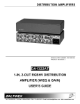
1
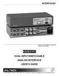
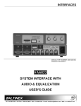
INTERFACES
MANUAL PART NUMBER: 400-0062-003
PRODUCT REVISION: 2
VA6835FC
SYSTEM UNIVERSAL INTERFACE
USER’S GUIDE
INTERFACES
INTRODUCTION
TABLE OF CONTENTS
Page
Altinex appreciates your purchase of the
VA6835FC Analog Interface. We are certain that
you will find it reliable and simple to use.
PRECAUTIONS / SAFETY WARNINGS ...............2
GENERAL ................................ .......................... 2
RACK MOUNT SAFETY GUIDELINES ..............2
INSTALLATION................................ ..................2
CLEANING................................ ......................... 2
FCC / CE NOTICE ................................ .............2
Superior performance for the right price, backed by
solid technical and customer support is what
Altinex has to offer.
The product you are holding in your hands is
designed using state-of-the-art technology and is
superior to anything available on the market. You
will find this and our other products reliable, long
lasting, and simple to operate.
ABOUT YOUR INTERFACE................................ ..3
TECHNICAL SPECIFICATION .............................. 3
VA6835FC DESCRIPTION................................ ....4
COMPUTER VIDEO INPUT (VGACOMPATIBLE 15-PIN HD CONNECTOR) .........6
LOCAL MONITOR OUTPUT (15-PIN HD
CONNECTOR) ................................ ...................6
MAIN (RGBS/RGBHV) OUTPUTS
THROUGH 6 BNC CONNECTORS.................... 6
HORIZONTAL POSITION ADJUSTMENT .........7
HORIZONTAL DELAY REMOVAL ..................... 7
POWER REQUIREMENTS ................................ 7
MOUNTING CAPABILITY ................................ ..7
BANDWIDTH ................................ ..................... 7
We are committed to providing our customers with
signal management solutions to the most
demanding audio-visual installations at very
competitive pricing.
We appreciate your selection of our products and
are confident that you will join the ranks of our
many satisfied customers throughout the world.
This manual covers:
VA6835FC VGA – Pack
VA6835FC MAC – Pack
VA6835FC SUN/SGI – Pack
VA6835FC RGB – Pack
VA6835FC Combo – Pack
VA6835FC Super – Pack
APPLICATION DIAGRAM…………………………..8
INSTALLING YOUR INTERFACE ......................... 8
OPERATION ................................ ......................... 9
SERRATION PULSE SWITCH........................... 9
HV OUT SWITCH ................................ ..............9
I.D. BIT SWITCH ................................ ................9
SYNC ON GREEN OUTPUT SWITCH...............9
TERMINATION SWITCH ................................ ...9
ACCESSORIES................................ ................... 10
FAQ (FREQUENTLY ASKED QUESTIONS) .......11
TROUBLESHOOTING GUIDE ............................ 12
ALTINEX POLICY ................................ ...............12
LIMITED WARRANTY................................ ......12
RETURN POLICY ................................ ............12
CONTACT INFORMATION .............................. 12
1
INTERFACES
PRECAUTIONS / SAFETY WARNINGS
1
Please read this manual carefully before using your
VA6835FC Interface. Keep this manual handy for
future reference. These safety instructions are to
ensure the long life of your VA6835FC and to
prevent fire and shock hazard. Please read them
carefully and heed all warnings.
•
1.1 GENERAL
•
•
•
Unauthorized personnel shall not open the unit
since there are high-voltage components
inside.
Qualified Altinex service personnel, or their
authorized representatives must perform all
service.
•
•
Maximum operating ambient temperature is 35
(degrees C).
Never restrict the airflow through the devices’
fan or vents.
When installing equipment into a rack, distribute
the units evenly. Otherwise, hazardous
conditions may be created by an uneven weight
distribution.
Connect the unit to a properly rated supply
circuit.
Reliable Earthing (Grounding) of Rack-Mounted
Equipment should be maintained.
•
•
•
•
•
•
•
Unplug the VA6835FC power cord before
cleaning. Clean surfaces with a dry cloth.
Never use strong detergents or solvents, such
as alcohol or thinner. Do not use a wet cloth or
water to clean the unit.
1.5 FCC / CE NOTICE
•
•
1.3 INSTALLATION
•
If the VA6835FC Interface is not used for an
extended period, disconnect the power cord
from the power outlet.
1.4 CLEANING
1.2. SAFETY GUIDELINES FOR THE RACKMOUNTING OF THE VA6835FC
•
to a table or wall, use only Altinex made
mounting accessories, such as brackets
(DA1293FC or DA1294FC) and cables for
optimum setup.
To turn off the main power, be sure to remove
the cord from the power outlet. The power
outlet socket should be installed as close to
the equipment as possible, and should be
easily accessible.
Do not pull the power cord or any cable that is
attached to the VA6835FC Interface.
For best results, place the VA6835FC
Interface on a flat, level surface in a dry area
away from dust and moisture.
To prevent fire or shock, do not expose this
unit to rain or moisture. Do not place the
VA6835FC Interface in direct sunlight, near
heaters or heat radiating appliances, or near
any liquid. Exposure to direct sunlight, smoke,
or steam can harm internal components.
Handle the VA6835FC Interface carefully.
Dropping or jarring can damage internal
components.
Do not place heavy objects on top of the
VA6835FC. If the VA6835FC is to be mounted
2
This device complies with Part 15 of the FCC
Rules. Operation is subject to the following two
conditions: (1) This device may not cause
harmful interference, and (2) this device must
accept any interference received, including
interference that may cause undesired
operation.
This equipment has been tested and found to
comply with the limits for a Class A digital
device, pursuant to Part 15 of the FCC Rules.
These limits are designed to provide
reasonable
protection
against
harmful
interference when the equipment is operated
in a commercial environment. This equipment
generates, uses, and can radiate radio
frequency energy and, if not installed and
used in accordance with the instruction
manual, may cause harmful interference to
radio communications. Operation of this
equipment in a residential area is likely to
cause harmful interference in which case the
user will be required to correct the interference
at his own expense.
INTERFACES
•
Main Video Output
Connector
Compatibility
Any changes or modifications to the unit not
expressly approved by Altinex, Inc. could void
the user’s authority to operate the equipment.
ABOUT YOUR INTERFACE
2
There are varieties of computers and computer
video cards on the market today. There are also
several data monitors and large screen data
projectors. When displaying a computer image on
a large screen data projector or on a large screen
monitor, it often becomes clear that some
computers are not always compatible with certain
display devices. The VA6835FC is a computer
video interface designed to resolve this
incompatibility.
Table 1. VA6835FC General
MECHANICAL
VA6835FC
Width (inches)
8.50in (216mm)
Height (inches)
1.75in (44mm)
Depth (inches)
4.93in. (125mm)
Weight (pounds)
2.0lbs (0.91kg)
Ship Weight (pounds)
4.0lbs (1.82kg)
Material
0.1" Aluminum
Finish
Gray
Faceplate
Lexan
T° Operating
10°C-35°C
T° Maximum
50°C
Humidity Technical
90% non-condensing
MTBF (calculations)
40,000 hrs
Table 2. VA6835FC Mechanical
The VA6835FC is a dual output computer Video
Interface. It is designed to interface a single VGA/
SVGA/ XGA/ UXGA/ MAC/ SUN or SGI computer
video source to two scan-rate compatible
presentation monitors or data projectors.
It is important to understand the general
capabilities of this interface. The VA6835FC does
not change the scan-rate or the resolutions of the
video signal so the source (computer) and display
(projector or monitor) must be scan-rate
compatible. The VA6835FC simply converts a
computer video signal to a pre-selected analog
format or separates the sync signal from the green
signal on output 1 if the input signal is RGsB.
ELECTRICAL
Input Video Signal
Analog Signal
Impedance
Rise/Fall Time (ns)
Input Sync Signal
Horizontal, Vertical, & C-Sync
Sync on Green
Impedance
Output Video Signals
Analog Signal
Impedance
Rise/Fall Time (ns)
Output Sync Signal
Composite Sync
Sync on Green
Impedance
Frequency Compatibility
Horizontal
Vertical
Minimum Video Bandwidth
Typical Video Bandwidth
The VA6835FC is a state-of-the art piece of
equipment with an exceptional combination of
compact size, advanced features, and very
competitive pricing.
TECHNICAL SPECIFICATIONS
Two sets of 6 BNC
Female
VGA/
SVGA/XGA/UXGA,
Apple/MACII/Quadra/G
3, Sun/SGI
Workstations
3
FEATURES/DESCRIPTION
VA6835FC
GENERAL
1
Input
Computer Video Input
15-pin HD Female
Connector
Local Monitor Output +
Output
Two Main Video
Outputs
Local Monitor Output
15-pin HD Female
Connector
3
VA6835FC
0.3 to 1.2 volt p-p
75 Ohms
0.9
TTL(+/-)
-0.3V
10 k Ohms
0.77 V p-p
75 Ohms
1.2
TTL(+/-)
-0.3V
22 Ohms
15-130 kHz
25-180 Hz
350 MHz
425 MHz
INTERFACES
Horizontal Position Range
Cross-talk
Power
Internal Power Supply
Power Consumption
Table 3. VA6835FC Electrical
VA6835FC DESCRIPTION
20 %
39dB @ 100MHz
90-140V/200-240V
4
4
INTERFACES
5
INTERFACES
designated Altinex adapter cables, such as VGA,
MAC, SUN, SGI, or RGB.
The VA6835FC has two key functions. It’s first
function is to amplify or buffer the signal to insure
that it is strong enough to travel distances of 100 ft
or farther through a coaxial cable. The second
function is to process the sync and to convert it to a
format that is acceptable to several displays.
PIN
No.
1
2
3
4
5
6
7
8
9
10
11
12
13
14
15
4.1 COMPUTER VIDEO INPUT (VGA
COMPATIBLE HD 15-PIN CONNECTOR)
The HD 15-pin connector input allows the
connection of a computer source to the interface
using Altinex input cables, which are available for
a variety of popular computers and graphics cards
on the market. These include VGA, MAC, SUN,
and SGI type video output connectors, with proper
cables. The VA6835FC input is compatible with
standard VGA cables.
PIN
No.
1
2
3
4
5
6
7
8
9
10
11
12
13
14
15
INPUT SIGNALS ON HD 15-PIN FEMALE
CONNECTOR
Red Video
Green Video
Blue Video
ID Bit (Grounded when ID Bit switch is ON)
Ground
Ground
Ground
Ground
No connection
No connection
ID Bit
ID Bit
Horizontal Sync/Composite Sync
Vertical Sync
No connection
LOCAL MONITOR OUTPUT SIGNALS ON
HD 15-PIN FEMALE CONNECTOR
Red Video
Green Video
Blue Video
ID Bit (Grounded when ID Bit switch is ON)
Ground
Ground
Ground
Ground
Composite Sync
No connection
ID Bit
ID Bit
Horizontal Sync
Vertical Sync
No connection
Table 5. Local Monitor Output pin-out
4.3 MAIN (RGBS/RGBHV) OUTPUTS THROUGH 6
BNC CONNECTORS
BNC connectors offer a reliable connection for
high-resolution video signals, and they facilitate
easy cable maintenance in the field. The
VA6835FC offers two main outputs with six BNC
connectors for each output. By selecting the
appropriate connectors, these outputs can provide
RGSB, RGBHV, or RGBS output signals.
For a RGsB type signal the “Sync on Green” dip
switch must be set to the ON position.
For a RGBHV type signal, you may either connect
cables to horizontal or vertical BNC connectors or
you may connect the horizontal channel to the
composite sync connectors by turning the “HV
Output” dip-switch to the ON position.
Table 4. VA6835FC Input pin-out
4.2 LOCAL MONITOR OUTPUT (HD 15-PIN
CONNECTOR)
With these connectors, the VA6835FC can be
connected to compatible data projectors using
3 coax, 4 coax, or 5 coax cables.
The HD 15-Pin connector output is used to
connect the local monitor to the interface. This is a
fully buffered output that eliminates reflections
often caused by “Y” type monitor breakout cables.
There is no need to terminate the unused output.
The “termination” switch on the VA6835FC affects
only the terminations of the computer video input.
The output is VGA compatible, but can also be
used to feed other types of local monitors using
6
INTERFACES
CONNECTOR
Red
Green
Blue
Sync
Hor.
Vertical
the power input connector displays the proper
voltage. To change the setting, unplug the
VA6835FC, and squeeze the clips on either side
of the fuse box. Pull out the fuse holder and turn it
180 degrees, resetting it with the proper voltage
shown through the window. Re-insert the fuse box
making sure that the side clips of the fuse box
lock securely into place.
MAIN DUAL OUTPUT (6-BNC
FEMALE)
Red Video
Green Video
Blue Video
Composite Sync/ Horizontal
Horizontal Sync
Vertical Sync
Table 6. VA6835FC dual (6 BNC) Output pin-out
4.7 MOUNTING CAPABILITY
4.4 HORIZONTAL POSITION ADJUSTMENT
The VA6835FC can be easily mounted into an
equipment rack. Four mounting holes are provided
on each side of the unit. To mount a single unit,
use Altinex 19”-1U Rack Mount Ears (part #
DA1294FC). To mount two units in tandem, use
an Altinex 19”-1U Rack Mount Shelf (part #
DA1293FC). For mounting under the table,
optional brackets, such as the TM1271, TM1272,
TM1273, or TM1274 can be used.
Most monitors and projectors have the ability to
adjust the horizontal position of the image, but
sometimes it is helpful to be able to control this
feature at the interface. This control is especially
useful when multiple computers are switched to a
single display, as the positions for each computer
might be slightly different.
By keeping the VA6835FC’s Horizontal Position
control dial in the center position, the image on the
display should first be adjusted using the monitor
or projector control. If necessary, turn the image
using the VA6835FC’s Horizontal Position Control
Dial.
4.8 BANDWIDTH
The typical bandwidth of the VA6835FC is 420
MHz. The minimum bandwidth is 350 MHz. This
exceptionally high bandwidth allows the passing of
the third harmonics of the video signal, thus
maintaining the highest quality of the input signal.
To turn off the Horizontal Position Control, turn the
adjustment dial fully to the right until a clicking
sound is heard.
4.5 HORIZONTAL DELAY REMOVAL
The VA6835FC offers the ability to by-pass
horizontal delay. This may be necessary when
interfacing with projectors or monitors with
sensitive sync inputs, particularly with LCD type
projectors. By turning the Horizontal Position
adjustment dial fully to the right, the control will
“click” into a locked position. In this position, the
VA6835FC outputs the same sync types, which
are fed into it from the source. In this setting, the
VA6835FC will not provide horizontal positioning.
The horizontal position adjustment of the image
must be made at the display.
4.6 POWER REQUIREMENTS
The VA6835FC may be used with either 90-140V
or 200-240V for ease of use throughout the world.
Always make sure that the fuse box window above
7
INTERFACES
APPLICATION DIAGRAM
5
INSTALLING YOUR INTERFACE
6
Step 5. Connect one end of a BNC cable to
output one or two of the VA6835FC units.
Connect the other end to the RGB input
on the projector or monitor. Usually either
a 4 BNC or 5 BNC coaxial cable is used,
depending on whether display devices
require composite sync or horizontal and
vertical sync signals.
Step 1. Please attach the Interface on the rack
using the provided rack mount hardware
on or under the furniture using the
optional TM Series Altinex brackets.
Step 2. Before you plug in the power cord to the
unit, please verify that the voltage rating
of 110V/220V on the FUSE CLIP located
at the rear of the unit is the same as the
power outlet. (Refer to section 4.6 for
changing the voltage).
Step 6. Make sure that the dip-switches are set
properly. For the desired sync output
format, refer to section 7.
Step 7. It is recommended that when the
Interface’s horizontal position control is
centered (or turned OFF), the horizontal
position of the image should first be
adjusted using the control provided by the
monitor or projector. If it is still required, it
can be adjusted using the Horizontal
Position Control dial located on the front
of the VA6835FC.
CONGRATULATIONS! YOU ARE DONE.
Step 3. Connect one end of the input cable
included with the Interface unit to the
video output connector of your computer
and the other end to the computer input
HD-15 port of the VA6835FC.
Step 4. If needed, connect the local monitor
output HD-15 connector of the VA6835FC
to the local monitor using the appropriate
Altinex Local Monitor cables. It is not
necessary to terminate this output with a
termination plug if a local monitor is not
being used.
If you experience any problems, please call
1-800-258-4623 or 1-714-990-2300 for
international calls.
8
INTERFACES
OPERATION
This is used primarily when interfacing to laptop
computers to imitate the presence of a local
monitor. Typically, this recognition will take place
during the boot up stage of a computer. If your
computer does not output video, place the ID Bit
switch in the ON position and reboot the
computer. When in the OFF position, the ID Bit
will be passed through the local monitor output
port.
7
According to Table 4, the settings of the
VA6835FC Interface can be adjusted using dipswitches. There are no other adjustments
necessary to operate the unit. The VA6835FC will
operate successfully as long as the cables are
attached properly and the technical specifications
are followed.
DIP-SWITCH
Serration
HV Output
Sync on Green
Termination
ID Bit
Not Used
OFF
X
X
X
ON
7.4 SYNC ON GREEN OUTPUT SWITCH
In some systems the ability of the VA6835FC to
output sync on green can be a very helpful
feature.
X
X
X
The VA6835FC separates the sync signal from
the green if the input is RGsB. So the output can
be either RGBS or RGBHV. The “Sync on Green”
dip-switch should be in the OFF position if the
desired output is RGBS or RGBHV for any type of
input. This dip-switch should be ON if the desired
output is RGsB.
Table 7. Dip switch default settings
7.1 SERRATION PULSE SWITCH
Certain monitors and projectors will exhibit better
stability when the serration pulse switch is “ON”.
This switch is seldom used and in most
circumstances should be turned “OFF”.
7.5 TERMINATION SWITCH
When the built-in termination switch is set to the
ON position, the input of the interface will be
terminated. As a rule, the termination switch
should be in the ON position. This switch does not
affect the termination of any output signal. The
termination switch should be left in the OFF
position if a “Y” cable is used at the local monitor
output connector.
7.2 HV OUT SWITCH
When the composite sync channel is used and
RGBS format is desired from the VA6835FC, the
HV OUT switch should be turned off. When this
switch is turned on, the composite sync channel
will output horizontal sync, but not vertical sync.
As an alternative to connecting cables to separate
horizontal and vertical channels, one can connect
horizontal sync to the composite sync and vertical
sync signal to the vertical connector, using the HV
OUT dip-switch in the ON position.
7.3 I.D. BIT SWITCH
Many computers use ID Bits or “Sense Pins” to
recognize the connection of a monitor to its video
output port. Often, these ID Bits will even allow the
computer to recognize what type of monitor is
connected (in terms of its scan rate
compatibility). When the I.D. Bit switch is in the
ON position, the VA6835FC allows the main ID Bit
(pin 4 on the input connector) to be connected to
the ground signal.
9
INTERFACES
ACCESSORIES
Model No.
DA1293SX
DA1294SX
TM1271
TM1272
TM1273
TM1274
MS8121CA
MS8122CA
MS8123CA
MS8124CA
MS8125CA
MS8126CA
MS8129CA
CB4103MR
CB4106MR
CB4112MR
CB4125MR
CB4150MR
CB4175MR
CB41100MR
CB41150MR
CB4203MR
CB4206MR
CB4212MR
CB4225MR
CB4250MR
CB4275MR
8
CB42100MR
Description
RACK MOUNT ACCESSORIES
Rack/Wall Shelf fits two VA6835FC
units side by side
Rack/Wall mount ears for single
VA6835FC
TABLE MOUNT BRACKETS
1U High, ½ Rack-Wide
1U High, ½ Rack-Wide with 15-pin
HD connector plate
1U High, ½ Rack-Wide with snap-in
connectors
1U High, ½ Rack-Wide with snap-in
& POWER connectors
INTERFACE CABLES
MAC Output cable for VA6835FC
MAC Input cable for VA6835FC
SUN Output cable for VA6835FC
SUN Input cable for VA6835FC
VGA Output cable for VA6835FC
VGA Input cable for VA6835FC
RGB Output cable for VA6835FC
4 BNC TO 4 BNC COAXIAL
CABLE
3 ft, 4 BNC to 4 BNC coaxial cable
6 ft, 4 BNC to 4 BNC coaxial cable
12 ft, 4 BNC to 4 BNC coaxial cable
25 ft, 4 BNC to 4 BNC coaxial cable
50 ft, 4 BNC to 4 BNC coaxial cable
75 ft, 4 BNC to 4 BNC coaxial cable
100 ft, 4 BNC to 4 BNC coaxial
cable
150 ft, 4 BNC to 4 BNC coaxial
cable
5 BNC TO 5 BNC COAXIAL
CABLE
3 ft, 5 BNC to 5 BNC coaxial cable
6 ft, 5 BNC to 5 BNC coaxial cable
12 ft, 5 BNC to 5 BNC coaxial cable
25 ft, 5 BNC to 5 BNC coaxial cable
50 feet, 5 BNC to 5 BNC coaxial
cable
75 feet, 5 BNC to 5 BNC coaxial
cable
CB42150MR
CB4406MR
CB4412MR
CB4425MR
CB4475MR
CB44100MR
CB44150MR
CB5000PL5BM00035BM
CB5000PL5BM00065BM
CB5000PL5BM00125BM
CB5000PL5BM00255BM
CB5000PL5BM00505BM
CB5000PL5BM00755BM
CB5000PL5BM01005BM
CB5000PL5BM01505BM
CB5000PL5BM02005BM
CB5000PL5BM02505BM
CB5100PL5BM00035BM
CB5100PL5BM00065BM
CB5100PL5BM00125BM
CB5100PL5BM00255BM
CB5100PL5BM00505BM
CB5100PL5BM00755BM
CB5100PL5BM01005BM
CB5100PL5BM01505BM
10
100 ft, 5 BNC to 5 BNC coaxial
cable
150 ft, 5 BNC to 5 BNC coaxial
cable
6 ft, 5 BNC to 5 BNC coaxial
12 ft, 5 BNC to 5 BNC coaxial
25 ft, 5 BNC to 5 BNC coaxial
75 ft, 5 BNC to 5 BNC coaxial
100 ft, 5 BNC to 5 BNC coaxial
150 ft, 5 BNC to 5 BNC coaxial
3 ft, 5 BNC M to 5 BNC M
6 ft, 5 BNC M to 5 BNC M
12 ft, 5 BNC M to 5 BNC M
25 ft, 5 BNC M to 5 BNC M
50 ft, 5 BNC M to 5 BNC M
75 ft, 5 BNC M to 5 BNC M
100 ft, 5 BNC M to 5 BNC M
150 ft, 5 BNC M to 5 BNC M
200 ft, 5 BNC M to 5 BNC M
250 ft, 5 BNC M to 5 BNC M
3 ft, 5 BNC M to 5 BNC M
6 ft, 5 BNC M to 5 BNC M
12 ft, 5 BNC M to 5 BNC M
25 ft, 5 BNC M to 5 BNC M
50 ft, 5 BNC M to 5 BNC M
75 ft, 5 BNC M to 5 BNC M
100 ft, 5 BNC M to 5 BNC M
150 ft, 5 BNC M to 5 BNC M
INTERFACES
use the
“HV OUT”
dip-switch?
200 ft, 5 BNC M to 5 BNC M
CB5100PL5BM02005BM
250 ft, 5 BNC M to 5 BNC M
CB5100PL5BM02505BM
All MS81 series cables listed above are 3 ft. long.
These cables are also available in 6 ft. and 12 ft.
lengths. Please call 1-714-990-2300 for a wider
selection of cables.
6
FAQ (FREQUENTLY ASKED QUESTIONS) 9
No:
1
2
3
4
5
Question
Why does
the
termination
switch have
to be “ON”?
Answer
The termination switch
should be ON if the local
monitor is connected
through a straight cable. It
will be OFF only if a monitor
breakout cable is used at the
local monitor output
connector.
When and
The “Horizontal Position”
why do I
Control dial enables or
need to use
disables the control of the
the
Horizontal Position of the
“Horizontal
image. First adjust the
Position”
horizontal position using the
Control dial? monitor or projector control,
and then use the horizontal
position control on the
VA6835FC, if needed.
What dipIf the desired output signal is
switch do I
composite sync, turn OFF
set to receive the “HV OUTPUT” dip-switch
the
and connect only 4 wires
composite
(RGBS) to the red, green,
sync output? blue, and sync connectors.
When and
The VA6835FC separates
why would I
the sync signal from green if
use the
the input is RGsB, so the
“Sync on
output can be either RGBS
Green” dipor RGBHV. This dip-switch
switch,
should be OFF if the desired
although the output is RGBS or RGBHV
unit does not for any type of input.
separate
Sync from
Green?
When do I
If the desired output is in
What is a
Common
Computer
Video Card
pin-out?
RGBHV format, turn ON the
“HV OUT” dip-switch. If the
“HV OUT” dip-switch is OFF,
the output signal may have
composite sync present on
the horizontal sync
connector.
See the following table for
Common Computer Video
Card pin-outs that can be
used with the VA6835FC.
PIN
MAC
VGA
SUN
No.
n/a
n/a
Red
A1
n/a
n/a
Green
A2
n/a
n/a
Blue
A3
Red
Gnd
Red
N/C
1
Red
Green
N/C
2
C.Sync
Blue
Sense
3
ID Bit 01
ID Bit
Sense Rtn
4
Green
N/C
C. Sync Sens
5
Green Gnd.
Red Rtn.
N/C
6
ID Bit 02
Green Rtn.
N/C
7
N/C
Blue Rtn.
N/C
8
Blue
N/C
N/C
9
ID Bit 03
Gnd
N/C
10
C/V Gnd.
ID Bit
11
V. Sync
ID Bit
12
Blue Gnd.
H. Sync.
13
H. Gnd
V. Sync
14
H. Sync
N/C
15
Table 8. Common Computer Video Card pin-outs
11
INTERFACES
TROUBLESHOOTING GUIDE
1.
When the correct voltage is applied to the
Interface, the power LED should be ON.
2.
The “Termination” dip-switch should be in the
ON position if a Y cable (breakout) is not
used on the input.
3.
Make sure the cables have the correct pinouts and the connection and quality of the
cables are good.
4.
Make sure that the source and display are
scan-rate compatible. The projector should
support an appropriate signal format (RGsB,
RGBS or RGBHV). Connect the projector
directly to a computer with a shorter cable to
verify the compatibility of display and source.
5.
6.
stability or reliability, or that has been subject to
misuse, negligence or accident.
10
11.2 RETURN POLICY
It is very important to Altinex that you receive the
products that you have ordered and that this
product fulfills your need. In the unlikely event,
that an Altinex product needs to be returned
please follow the policies below:
Altinex will accept product returns for a period of
30 days from authorized Altinex dealers. Products
must be returned in an unopened package.
If a product has been opened, the restocking fees
will apply. For the restocking fee amount, please
contact an Altinex Sales Representative.
If the product is in your possession for more than
30 days, the restocking fees will apply.
If you are using output RGBS or RGsB then
the “HV Output” dip-switch is the OFF
position and the composite sync signal is
taken from the sync connector. If the display
needs an RGBHV signal then the “HV
Output” dip-switch must be in the ON position
if the sync and vertical connectors are used.
Altinex will not accept any returns on cables or
custom products.
If your product is in warranty and needs service,
contact the Altinex Sales Department for an RMA
(Return Material Authorization). Products returned
without an RMA number may experience a delay
in service.
If the desired output is RGsB, the sync ON
GREEN dip-switch should be ON.
ALTINEX POLICY
If your product is out of warranty and needs
service, contact the Altinex Sales Department for
an RMA (Return Material Authorization). Products
returned without an RMA number may experience
a delay in service. The service charges will be
quoted to you before actual repairs are done.
11
11.1 LIMITED WARRANTY
Altinex warrants that its products and cables are
free from defects in materials under normal use
and service. This warranty is limited to repairing at
company’s factory any part or parts of the product,
which upon company’s examination shall disclose
to be, thus defective. Products considered
defective should be returned to company with
transportation charges pre-paid within 2 years (90
days for cables) from date of shipment to the
purchaser. The warranty is expressly instead of all
other warranties expressed or implied. Altinex
neither assumes nor authorizes any other person
to assume for it any other liability in connection
with the sale of the products. This warranty shall
not apply to any product that shall have been
repaired or altered outside of company’s factory in
any way so as, in its judgment, to affect its
11.3 CONTACT INFORMATION
Sales Department
Phone:
714-990-2300
Fax:
714-990-3303
Accounting Department
12
Phone:
714-990-6088
Fax:
714-990-5778