1
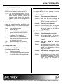
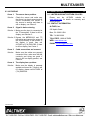
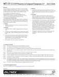
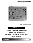
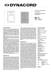
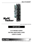
MULTITASKER®
MANUAL PART NUMBER: 400-0443-004
MT115-111
DUAL TWISTED PAIR RECEIVER TO
COMPUTER/COMPONENT VIDEO + AUDIO,
USER’S GUIDE
MULTITASKER
TABLE OF CONTENTS
Page
PRECAUTIONS / SAFETY WARNINGS................ 2
GENERAL..........................................................2
HANDLING ........................................................2
CLEANING.........................................................2
FCC NOTICE .....................................................2
ABOUT YOUR MT115-111....................................... 3
TECHNICAL SPECIFICATIONS.............................. 3
PRODUCT DESCRIPTION ...................................... 5
APPLICATION DIAGRAMS...................................... 6
DIAGRAM 1: TYPICAL SETUP ..........................6
DIAGRAM 2: INTERNAL VIEW ..........................7
DIAGRAM 3: SWITCH SETTINGS .....................8
INSTALLING YOUR MT115-111 ............................ 9
OPERATION ............................................................... 9
RS-232 CONTROL.............................................9
DESCRIPTION OF COMMANDS .....................10
COMMAND ORGANIZATION ......................10
BASIC COMMANDS ....................................10
FEEDBACK CONTROL ...............................12
CARD CONTROL ........................................13
ID COMMANDS ...........................................14
GROUP COMMANDS..................................15
SUMMARY OF COMMANDS ...........................16
MENU MODE ...................................................17
TROUBLESHOOTING GUIDE............................... 19
LEDS ARE OFF ................................................19
DISPLAY IS TOO BRIGHT ...............................19
NO DISPLAY....................................................20
ALTINEX POLICIES ................................................ 20
LIMITED WARRANTY/RETURN POLICIES .....20
CONTACT INFORMATION ..............................20
400-0443-004
1
MULTITASKER
PRECAUTIONS / SAFETY WARNINGS
•
1
Please read this manual carefully before using your
MT115-111 and keep it handy for future reference.
These safety instructions are to ensure the long life
of your MT115-111 and to prevent fire and shock
hazards. Please read them carefully and heed all
warnings.
1.1 GENERAL
•
Qualified ALTINEX service personnel or its
authorized representatives must perform all
service.
1.2 HANDLING
•
•
•
•
Handle the MT115-111 carefully. Dropping or
jarring can damage the card.
The MT115-111 contains components that are
sensitive to electrostatic discharge (ESD).
Always use ESD safety precautions when
touching the card.
To prevent fire or shock, do not expose this unit
to water or moisture. Do not place the
MT115-111 in direct sunlight, near heaters or
heat-radiating appliances, or near any liquid.
Exposure to direct sunlight, smoke, or steam can
harm internal components.
Do not pull any cables that are attached to the
MT115-111.
•
1.4 CLEANING
•
Clean only the connector area with a dry cloth.
Never use strong detergents or solvents such as
alcohol or thinner. Do not use a wet cloth or
water to clean the card. Do not clean or touch
any component or PCB.
1.5 FCC NOTICE
•
This device complies with Part 15 of the FCC
Rules. Operation is subject to the following two
conditions: (1) This device may not cause
harmful interference, and (2) this device must
accept any interference received, including
interference that may cause undesired
operation.
400-0443-004
2
This equipment has been tested and found to
comply with the limits for a Class A digital device
pursuant to Part 15 of the FCC Rules. These
limits are designed to provide reasonable
protection against harmful interference when the
equipment is operated in a commercial
environment. This equipment generates, uses,
and can radiate radio frequency energy and if
not installed and used in accordance with the
instructions found herein, may cause harmful
interference to radio communications. Operation
of this equipment in a residential area is likely to
cause harmful interference in which case the
user will be required to correct the interference
at his expense.
Any changes or modifications to the unit not
expressly approved by ALTINEX, Inc. could void
the user’s authority to operate the equipment.
MULTITASKER
ABOUT YOUR MT115-111
2
TECHNICAL SPECIFICATIONS
Specifications are subject to change.
See www.altinex.com for up-to-date information.
MT115-111
Dual Twisted Pair Receiver to
Computer/Component Video+ Audio,
FEATURES/
DESCRIPTION
The MT115-111 provides a means of receiving
computer or component video and audio signals
over Twisted Pair-type (CAT-5) cable when used
together with an ALTINEX Twisted Pair Video
Transmitter, such as the MT115-110 or TP115-110.
MT115-111
Inputs
CAT-5/6 Twisted Pair
(2) RJ-45 female
Output
The MT115-111 offers two 15-pin HD female
outputs and two 3.5 mm audio outputs, one for
each of the inputs. The RJ-45 inputs receive the
differential video and audio signals generated by
the Twisted Pair transmitter. The MT115-111 also
offers video equalization for long cable lengths. The
equalization adjustment may be set for either
hardware or software (RS-232) control.
Video
(2) 15-pin HD female
Audio
(2) 3.5 mm jack
Compatibility
Signal Types
Video Signal
Resolutions
Additionally, the MT115-111 offers the option for
video gain adjustments through RS-232 control or
the gain may be set to a value of one for hardware
control.
Recommended Max.
Cable Lengths
Note: Measurements
made using ALTINEX
low-skew cable,
CB3150PV.
As an added feature, the MT115-111 offers the
option of selecting a Sync-on-Green (SOG) output.
The SOG feature is a simple switch setting that
may be set for SOG or standard RGBHV.
ALTINEX Standard for
Twisted Pair
VGA through UXGA
480p through 1080i
VGA:
640x480@60Hz
900 ft (274 m)
XGA:
1024x768@60Hz
700 ft (213 m)
SXGA: 1280x1024@60Hz
650 ft (198 m)
UXGA: 1600x1200@60Hz
600 ft (183 m)
The latest generation of Twisted Pair devices uses
an innovative, patented technology* developed by
ALTINEX. The new signal processing technology
allows transmitting and receiving fully equalized
computer video signals, stereo, and audio signals
over long distances.
Table 1. MT115-111 General
MECHANICAL
MT115-111
Enclosure Slots
One
Weight
* US Patent 7,065,190
10°C-35°C
T° Maximum
50°C
MTBF (calculations)
Table 2. MT115-111 Mechanical
3
0.5 lb (0.23 kg)
T° Operating
Humidity
400-0443-004
3
90% non-condensing
40,000 hrs (min.)
MULTITASKER
ELECTRICAL
MT115-111
Input Signal
CAT-5/6 Twisted Pair
Video/Sync/Audio Signals
ALTINEX Standard
Audio Output Signal
Gain
0 dB +/- 0.5 dB
Level
1.0 Vp-p max
Video Output Signal
Video Signal
1.0 Vp-p max
Video Impedance
75 ohm
SYNC Signal
TTL (+/-)
Video Resolutions
VGA through UXGA
480p through 1080i
Power (from enclosure)
+6V
0.600 A (3.6 W)
-6V
0.350 A (2.1 W)
Total Power Consumption
5.7 W max.
Table 3. MT115-111 Electrical
400-0443-004
4
MULTITASKER
PRODUCT DESCRIPTION
400-0443-004
4
5
MULTITASKER
APPLICATION DIAGRAMS
5
DIAGRAM 1: TYPICAL SETUP
MT115-111
TP115-110
TP115-110
400-0443-004
6
MULTITASKER
DIAGRAM 2: INTERNAL VIEW
MT115-111
PS
CH1
SIGNAL
DETECT
POWER
CH2
SIGNAL
DETECT
POWER
MP
L
PAIR 4
R
INPUT 1
4TP
RJ-45
SYNC
SEPARATOR
V
PAIR 2
H
R/Pr
PAIR 3
B/Pb
PAIR 1
G/Y
S/W
EQ
EQ
L
R
SYNC
SEPARATOR
PAIR 2
PAIR 3
B/Pb
PAIR 1
G/Y
EQ
400-0443-004
H/W
EQ
7
MONO
AUDIO
3.5 mm
V
H
R/Pr
S/W
RGBHV
YPbPr
VIDEO
15-PIN HD
H/W
PAIR 4
INPUT 2
4TP
RJ-45
MONO
AUDIO
3.5 mm
RGBHV/
YPbPr
VIDEO
15-PIN HD
MULTITASKER
DIAGRAM 3: SWITCH SETTINGS
SW8
GAIN2
GAIN1
EQ2
EQ1
SW7
400-0443-004
SW6
SW3
SOG1
SOG2
SW4
SW1
CONTROL
OUTPUT
CONTROL DESCRIPTION
Video Gain
1
2
Set SW6 to SW for software or HW for a fixed gain = 1.
Set SW8 to SW for software or HW for a fixed gain = 1.
Equalization
1
2
Set SW4 to SW for software or HW for hardware.
Set SW2 to SW for software or HW for hardware.
Sync-on-Green
1
2
Set SW3 to ON for a Sync-on-Green output.
Set SW1 to ON for a Sync-on-Green output.
8
MULTITASKER
INSTALLING YOUR MT115-111
6
OPERATION
Step 1. Determine the appropriate switch settings
using DIAGRAM 3 on page 8.
7.1 RS-232 CONTROL
The
MT115-111
has
many
advanced
remote-control capabilities accessible through
standard RS-232 communication. Control may be
accomplished through a computer, control system,
or any device capable of RS-232 communication.
Step 2. Turn off power to the MultiTasker system
and disconnect from AC power.
Step 3. Remove
an
unused
slot
cover
(MT200-101). Identify the slot number and
note that it is for RS-232 control.
7.1.1 RS-232 INTERFACE
Step 4. Slide the MT115-111 into the enclosure in
order to connect it to the bus. Make sure
that the card fits into place and secure the
card by tightening its retainer screws.
The control commands for the MT115-111, are
in a simple ASCII character format.
Step 5. Restore power to the MultiTasker
enclosure. The LEDs for each input
should be on and red.
Step 6. Connect the computer/component video
and audio devices to Outputs 1 and 2.
1.
Square brackets “[ ]” are part of the
command.
2.
Use uppercase letters for all commands.
3.
Spaces are not legal characters.
The cards in a MultiTasker are capable of
performing various functions, as well as
providing feedback to the user or control
system. Commands instruct a card to perform
specific actions or request information from the
card. Some commands do both simultaneously.
Step 7. Connect the 4TP IN1 to the output of its
Twisted Pair transmitter. If a properly
formatted input signal is available, the
input LED will turn green.
A command that instructs the card only to
perform an action will generate feedback of “[ ]”.
The open bracket immediately followed by a
closed bracket indicates the card received a
valid command. If the command requested
information from the card, the feedback
generated by the card is the acknowledgement
of having received a valid command. Invalid
commands generate feedback that includes
“ERR” plus an error code.
Step 8. Connect the 4TP IN2 to the output of its
Twisted Pair transmitter. If a properly
formatted input signal is available, the
input LED will turn green.
Step 9. The MT115-111 is ready for operation.
Step 10. Video equalization is provided to fine-tune
the displayed image on the remote
display. The equalization adjustments on
the MT115-111 and Twisted Pair
transmitter
work
together.
Adjust
equalization
by
setting
both
the
transmitter and receiver to minimum. Then
slowly increase the equalization on the
receiver until an image is present. Then
adjust the equalization on both units for
the best image.
Example 1: [ERR001]
Error number
Example 2: [ERRC04]
Card error C4
Commands ending in “S” will be saved into
memory. Commands not ending in “S” will still
be executed, but will not be restored when the
system is reset or powered off, then on.
Step 11. The MT115-111 also has video gain
adjustment capability through RS-232
control. See the following section for
RS-232 command details.
400-0443-004
7
9
MULTITASKER
7.2 DESCRIPTION OF COMMANDS
Each command consists of three
Function, Card ID, and Unit ID.
[ Function , Card ID , Unit ID ]
COMMAND ORGANIZATION
parts:
The RS-232 commands in this section are
organized into the following 5 categories:
Basic Commands
Feedback Control
Card Control
Card IDs
Groups
Example: [VERC3U2]
VER
C3
U2
= Function
= Card ID or Group ID
= Unit ID (optional for Unit ID 0)
For Function, see a detailed explanation under
each command description.
See the SUMMARY OF COMMANDS (Section 7.3)
for one-line descriptions of each command.
The card ID is a unique identifier. It is equal to
the enclosure slot number, or it may be an
assigned value. As the slot number, the value
can range from 1-4 up to 1-20 depending on the
enclosure. If the value is assigned, the ID may
be a maximum of 99. Card ID 0 (C0) is used for
the controller and cannot be reassigned.
BASIC COMMANDS
The basic commands are used to provide general
information about the card. These commands are
most useful during the initial stages of setting up
and operating the card.
1. [VER]
This command displays the software version
and card type for the MT115-111 card.
The group ID is a number representing a group
of cards defined with the [WR] command. When
using the group ID, all cards in the group will
perform the given instruction.
Command Format: [VERCn]
Cn = Card ID (n = slot # from 1 to max slots)
NOTE: In this guide, cards are referenced by
their IDs (C1, C2...C99). Typically, the ID
number will be equivalent to the slot number.
Groups will be referenced by their IDs (G1-G8).
Example:
An MT115-111 card is in slot 4. Send the
command [VERC4], and the system will return
feedback similar to the following:
Changing the position of a card will significantly
affect the commands recorded on software
definitions or third-party control systems.
[MT115-111 690-0231-001 C04]
MT115-111
The unit ID has a range from U0 to U20. U0
should be used for single unit operation. If the ID
is set to U0, each command may be used
without Ui. Use the command [SETU0], as
explained in the MT101-101 User’s Guide.
690-0231-001 = Firmware version
C04
Example:
[VERC3]:
For U0
[VERC3Ui]: For ID other than U0
[VERC3]:
Equivalent to [VERC3U0]
400-0443-004
= Card model number
10
= Card ID
MULTITASKER
2. [C]
5. [CLR]
This command receives the status of the card.
Cn = Card ID (n = # from 1 to max slots)
This command clears the card settings and
returns it to the factory default values. The
defaults gain setting is 4 and the default
equalization setting is 32 for each input.
Example:
Command Format: [CLRCn]
There is one MT115-111 card in slot 4. Sending
the command [C4] to the system will yield
feedback similar to the following:
Cn = Card ID (n = slot # from 1 to max slots)
Command Format: [Cn]
Example:
In order to clear the card in slot 4, send the
command [CLRC4]. The card will respond with
the following feedback when complete:
INPUT#1 VIDEO GAIN 4
EQUALIZATION 32
INPUT#2 VIDEO GAIN 4
EQUALIZATION 32
FACTORY RESET COMPLETED
6. [TEST]
In this case, both card inputs are set for a video
gain of 4 and an equalization of 32.
This command performs a series of tests on the
internal memory and displays a pass message if
successful. Otherwise, failures are indicated.
If there is no card in slot 4, sending the [C4]
command will not return any feedback.
3. [CnS]
Command Format: [TESTCn]
This command saves the card settings and
displays the status. After the system is reset or
powered off and on, the settings are restored.
Cn = Card ID (n = slot # from 1 to max slots)
Upon completion, the system will display the
results. This feedback will be similar to the
following:
Cn = card number
S
= save configuration
MEMORY IC TEST RESULTS:
MEMORY IC PASS
Example:
7. [HELP]
Save the status by sending [C4S].
The
feedback returned will be similar to the following:
This command displays information available for
the MultiTasker interface commands.
INPUT#1 VIDEO GAIN 4
EQUALIZATION 32
INPUT#2 VIDEO GAIN 4
EQUALIZATION 32
SAVED
Command Format: [HELPCn]
Cn = Card ID (n = # from 1 to max slots)
Example:
In order to display the RS-232 commands
available for the MT115-111 card in slot 4, send
the command [HELPC4]. The commands along
with a brief description will be displayed in the
Terminal Window.
4. [...S]
This command will save the configuration
command being sent in memory. When sending
the command [EQ1=16C4S], after reset or
power up, the equalization for Input 1 will be set
to 16.
400-0443-004
11
MULTITASKER
10. [?C]
FEEDBACK CONTROL
The next commands are a function of both the card
and the front panel and allow flexibility over when
and how card information is displayed.
This command will return general information
about the card and its status.
8. [FBD]
Cn = Card ID (n = # from 1 to max slots)
Command Format: [?Cn]
This command turns feedback delay on or off. It
is necessary when installing some newer cards
in older systems. If the system does not receive
all of the feedback from the card, the card may
be communicating too fast. This command will
slow down the card's communication rate.
Example:
The MT115-111 in slot 4 has Inputs 1 and 2 set
to their default values. Send the command [?C4]
to receive feedback similar to the following.
[(MT115-111C04) (VR690-0231-001C04)
(GN0404C04) (EQ3232C04)]
Command Format: [FBDm]
m
All feedback is enclosed in square brackets.
Each data field in the status is in parentheses.
The first two characters identify the status type
and the last three are the card’s ID.
= Delay (0= no delay, 1= delay 100mS)
Example:
The command [HELPC4] is sent to the card in
slot 4. Some of the HELP file is displayed on the
screen, but most is missing. Send the command
[FBD1] to slow down the rate at which the card
sends feedback to the system.
MT115-111
VR690-0231-001
GN0404
EQ3232
9. [?]
= Card model number
= Firmware version
= Video gain levels
= Equalization settings
The video gain levels are displayed for both
Input 1 and Input 2. The first 2 digits are the
setting for Input 1 and the last 2 digits are the
setting for Input 2. In this case, both are set to a
level of 4 out of 11.
This command will return general information
about the MultiTasker and cards installed in the
unit.
Command Format: [?Ui]
Ui = Unit ID (i = from 0 to 9)
The equalization levels are displayed for both
Input 1 and Input 2 as well. The first 2 digits are
the setting for Input 1 and the last 2 digits are
the setting for Input 2. In this case, both are set
to a level of 32 out of 64.
Example:
A MultiTasker with unit ID 1 has a front panel
with part number MT101-101 and contains an
MT103-122 and MT115-111. Send the
command [?U1] and receive the following:
11. [STA1]
This command enables automatic feedback
from the front panel. The command affects any
card with auto-feedback capability, not just the
MT115-111. The power on default or reset is
STA0, off. For more details, see the [?Cn]
command definition.
[(MT101-101U1)(MT103-122C01)
(MT115-111C04)]
MT101-101U1 = Panel number/unit ID
MT103-122C01 = MT103-122 is in slot 1
MT115-111C04 = MT115-111 is in slot 4
Command Format: [STA1]
400-0443-004
12
MULTITASKER
Feedback Prefix Definitions:
MT
Card Model Number
VR
Firmware Revision
GN
Video Gain Levels
EQ
Equalization Levels
CARD CONTROL
Example:
14. [EQ=]
Command =
Feedback =
Card control commands allow the main functions of
the card to be executed over the RS-232 bus, or
from the front panel’s programmable keys.
This command sets the equalization for an input
to a value specified by the user.
[EQ1=1C4]
(EQ0132C04)
EQ = Equalization
01 = Input 1 Equalization
32 = Input 2 Equalization
C04 = Card ID
Command Format: [EQm=xCn]
12. [STA0]
x
= Equalization level (m = # from 1 to 64)
Example:
Set the equalization on Input 2 of C4 to a value
of 32 by sending the command [EQ2=32C4].
The card will respond with feedback of “[ ]” once
the command is executed.
Command Format: [STA0]
15. [GAIN]
13. [EQ]
This command displays the gain setting for an
input and selects that input for adjustment using
the [+] and [-] commands. A gain setting of 4 is
equivalent to unity gain.
This command displays the equalization setting
for an input and selects that input for adjustment
using the [+] and [-] commands.
Command Format: [EQmCn]
Command Format: [GAINmCn]
= Input # (m = 1 or 2)
m
Cn = Card ID (n = slot # from 1 to max slots)
= Input # (m = 1 or 2)
Cn = Card ID (n = slot # from 1 to max slots)
Example:
Example:
Display the equalization setting for Input 1 of C4,
then increase the equalization level by 3 from a
starting value of 12.
Display the gain setting for Input 2 of C4, then
decrease the gain level by 3 from a starting
value of 10.
Send the command [EQ1C4] and the current
setting for Input 1 will be displayed.
Send the command [GAIN2C4] and the current
setting for Input 1 will be displayed.
[12]
[10]
Next, send the commands [+], [+], and [+] to
increase the setting by 3. Send the [EQ]
command again to receive new value.
Next, send the commands [-], [-], and [-] to
decrease the setting by 3. Send the [GAIN]
command again to receive new value.
[15]
400-0443-004
= Input # (m = 1 or 2)
Cn = Card ID (n = slot # from 1 to max slots)
This command disables automatic feedback
from the card and front panel. The command
affects all cards with auto-feedback capability,
not just the MT115-111. The default at power
on or reset is STA0, OFF.
m
m
[7]
13
MULTITASKER
16. [GAIN=]
17. [RSI]
This command sets the gain level for an input to
a value specified by the user. A gain setting of 4
is equivalent to unity gain.
This command resets the card IDs in the
system. After sending this command, each card
ID in the system will match the slot number of
the card. If the card is moved to another slot, its
ID number will be the new slot number.
Command Format: [GAINm=xCn]
m
= Input # (m = 1 or 2)
x
= Gain level (m = # from 1 to 11, 4 = unity)
Command Format: [RSI]
Example:
Cn = Card ID (n = slot # from 1 to max slots)
Send the command [RSI] to the system with
Unit ID 0. The card in slot 1 will have ID 1, the
card in slot 2 will have ID 2, and so on. If the
card in slot 1 is then moved to slot 4, the card ID
will then be 4.
Example:
Set the gain level for Input 2 of C4 to a value of
4 by sending the command [GAIN2=4C4]. The
card will respond with feedback of “[ ]” once the
command is executed.
18. [SIDn]
This command sets all the cards installed in the
MultiTasker system to the same card ID. After
sending this command, all cards will be
addressed with the same ID. Use caution when
sending this command to a system with multiple
board types.
ID COMMANDS
The default card ID is the same as the card slot
number. The next several commands allow the
user to change the card ID to a value other than the
slot number. Once the ID is changed, moving the
card to another slot will not change the card ID. If a
card in slot 4 is set to ID 1, then moved to slot 10,
its ID will remain 1. The [RSI] command forces
each installed card to take its slot number as its ID
number, regardless of the slot in which it is
installed.
Command Format: [SIDn]
n
= Card ID (n = # from 1 to 99)
Example:
Send the command [SID1] to the system. All the
cards in the system now have ID 1. Any
commands that are sent to card ID 1 will be
received and executed by each card.
Some cards require more than one slot in the
MultiTasker system. As an example, some matrix
switcher cards require 4 slots. If 5 of these cards
are installed, they would be numbered C4, C8,
C12, C16, and C20. Changing the ID allows the
user to define the cards as C1, C2, C3, C4, and C5.
19. [SIDnCi]
This command sets the card ID of a single card
to a number from 1 to 99.
Another use for changing the card ID is to be able
to use multiple systems without having to set each
unit to a different unit ID. All systems may be left as
unit ID 0 for ease of programming. The cards in the
first unit may be numbered 1-10 and in the second
unit 11-20.
Command Format: [SIDnCi]
n = Card ID (n = # from 1 to 99)
Ci = Slot Number (i = # from 1 to max slots)
Example:
Send the command [SID50C10] to set the ID of
the card in slot 10 to an ID of 50.
400-0443-004
14
MULTITASKER
20. [SID+]
GROUP COMMANDS
This command sets the card ID of all cards in a
system to their slot number plus the offset value.
Group commands allow several cards with the
same functions to be controlled simultaneously with
a single command. Up to 8 groups (G1-G8) may be
defined. These commands apply to all cards, not
only the MT115-111.
Command Format: [SID+n]
n = Offset amount (n = # from 0 to 99)
The maximum card ID is 99, so subtract
the highest slot number from 99 to find
the maximum offset. For example, in an
8-slot enclosure, the maximum offset
would be 91. The slot number (8) plus the
offset (91) equals 99.
22. [WR]
This command adds cards to a group. In
MultiTasker systems with audio and video cards,
the groups are typically as follows:
Group 1 = Video Cards
Group 2 = Audio Cards
Group 3 = Video and Audio Cards
Example:
There are two 20-slot enclosures to be
connected together during normal operation.
The first unit will use the default IDs where the
card ID is equal to the slot number. The second
unit will have the same unit ID, but each card ID
will be offset by 20.
Command Format: [WRCn1Cn2…Gk]
Cn = Card ID (n = slot # from 1 to max slots)
Gk = Group ID (k = # from 1-8)
Connect the computer to the second unit only
and send the command [SID+20] to set the ID of
all the cards in the second enclosure to their slot
number plus 20, then reconnect both units.
Example:
The cards in the first unit will be referenced as
card IDs 1-20 and the cards in the second unit
will be referenced by card IDs 21-40.
Now add C8 to G5 by sending [WRC8G5]. C8 is
added to G5, and G5 is not overwritten. View
the contents of G5 by sending [RDG5] and
receiving the following feedback:
Add C2, C4, and C6 to G5 by sending the
command [WRC2C4C6G5]. After executing this
command, G5 will consist of C2, C4, and C6.
21. [RSN]
[G5=C2C4C6C8]
This command displays the slot number of a
card with a specified ID number. If more than
one card has the same ID, each slot number will
be displayed.
23. [RMC]
This command removes one or more cards from
a group.
Command Format: [RSNCi]
Command Format: [RMCn1Cn2…Gk]
Ci = Card ID (i = # from 1 to 99)
Cn = Card ID (n= # from 1 to max slots)
Example:
Gk = Group ID (k = # from 1-8)
The card in slot 4 takes up four slots in the
enclosure. Its ID was set to 1 since it is the first
card installed in the system, reading from left to
right. Send the command [RSNC1] to find the
slot number of this card. The system responds
with the following feedback:
Example:
G5 consists of C2, C4, C6, and C8. Remove C6
and C8 by sending [RMC6C8G5]. View the
contents of G5 by sending [RDG5] and receiving
the following feedback:
[4]
400-0443-004
[G5=C2C4]
15
MULTITASKER
24. [RMG]
7.3 SUMMARY OF COMMANDS
This command deletes one or all groups.
Basic Commands
Command Format: [RMGk]
1)
[VER]
Display firmware version
Gk = Group ID (k = # from 1-8, * for all)
2)
[C]
Display card status
Example:
3)
[CnS]
Save card settings
Remove all cards from G52 by sending [RMG5].
The system will return the following feedback:
4)
[..S]
Save current setting
5)
[CLR]
Reset card to defaults
6)
[TEST]
Test internal memory ICs
7)
[HELP]
Display available commands
[G5=0]
Example 2:
Remove all cards from all groups, effectively
deleting all groups, by sending [RMG*]. The
system will return the following feedback:
Feedback Commands
G1-G8: EMPTY
8)
[FBD]
Feedback delay on/off
9)
[?]
Display system cards
10) [?C]
Display card information
This command reads and then displays the
members in a group.
11) [STA1]
Auto-feedback on
12) [STA0]
Auto-feedback off
Command Format: [RDGk]
Card Commands
Gk = Group ID (k = # from 1-8)
13) [EQ]
Select equalization adjustment
Example:
14) [EQ=]
Set equalization level
C2, C4, and C6 make up G5. Read the member
data for G5 by sending the command [RDG5].
The system will return feedback as follows:
15) [GAIN]
Select video gain adjustment
16) [GAIN=]
Set video gain level
[G5=C2C4C6]
ID Commands
The feedback shows G5 and then the cards that
make up G5. In this case, G5 includes C2, C4,
and C6.
17) [RSI]
Reset Card IDs to defaults
18) [SIDn]
Set all Card IDs
19) [SIDnCi]
Set one Card ID
20) [SID+]
Set all Card IDs to an offset
21) [RSN]
Display card slot number
25. [RD]
Group Commands
400-0443-004
16
22) [WR]
Add card(s) to a group
23) [RMC]
Remove card(s) from group
24) [RMG]
Delete group
25) [RD]
Display group members
MULTITASKER
7.4 MENU MODE
Menu Mode commands allow virtually the same
functionality as programming commands. Unlike
the programming commands in the previous
sections, menu commands prompt the user to
select from a list of available options. The system
then responds based upon selections made by the
user.
4.
Enter the ID number of the desired system.
In the example above, enter a “1” for the
MultiTasker with unit ID 1.
5.
The system then interrogates all the cards
available in its enclosure and displays a list
of available cards.
Example:
7.4.1 MENU COMMAND DEFINITIONS
Refer to section 7.2 for details on card functions
and examples. Following is a cross-reference
between menu mode and programming
commands.
MENU
6.
Enter the 2-digit ID and a menu for the card
will be displayed. In the example above,
enter “04” for the MT115-111.
7.
The system will prompt for selections
specific to the selected card.
8.
Read each menu carefully, and continue
selecting keys as prompted.
COMMAND
Equalization
[EQ]
Gain
[GAIN]
Save
[CnS]
Reset
[CLR]
Version
[VER]
Status
[C]
Help
[HELP]
NOTE: Menus for data entry have two
prompts: “Key=” and “ESC” (escape). Press the
escape key to return to the previous menu.
7.4.3 MENU TYPES
1.
Do NOT press any keys except those relating to
the current menu. If you press the ENTER key
after entering a letter or digit, the original list of
systems will be displayed.
In order to enter Menu Mode, the system
needs to be connected to a computer
running RS-232 control software.
2.
In the Terminal Window, press the ENTER
key on the keyboard.
3.
The system checks all MultiTaskers on the
RS-232 bus and displays a list of available
systems.
Example:
400-0443-004
MAIN MENU
The first menu displayed after selecting the
card is the Main Menu. This menu provides
access to the key functions related to the
card. Press the key representing the menu
item for access and a sub-menu will appear.
7.4.2 USING MENU MODE
1.
01: MT103-122
02: MT103-123
04: MT115-111
2.
SUB-MENUS
Each menu item will display either a
sub-menu, or a list of options. Press the key
corresponding to the desired choice.
1: U1
2: U2
3: U3
17
MULTITASKER
2: GAIN CONTROL
GAIN CONTROL
1: INPUT#1 4
GAIN CONTROL INPUT#1 (4)
1: INCREASE GAIN LEVEL
2: DECREASE GAIN LEVEL
2: INPUT#2 4
GAIN CONTROL INPUT#2 (4)
1: INCREASE GAIN LEVEL
2: DECREASE GAIN LEVEL
3: SAVE CONFIGURATION
SAVE CURRENT CONFIGURATION?
1: YES
2: NO
4: RESET CONFIGURATION TO DEFAULT
RESET CARD TO FACTORY DEFAULT?
1: YES
2: NO
5: VERSION
This selection displays the card firmware
version and then redisplays the Main Menu. It
is equivalent to the [VER] command.
7.4.4 MT115-111 MENUS
Following are the menus available to the
MT115-111. The first menu is the Main Menu
only. The second listing is an expanded view of
the card’s sub-menus.
The expanded menu contains values that
indicate the current setting or value of a
parameter. The value is usually in parentheses,
or otherwise indicated at the top of a sub-menu.
In some cases, additional comments are
provided for clarification and are not part of the
menu feedback.
MT115-111 MAIN MENU
1: EQUALIZATION CONTROL
2: GAIN CONTROL
3: SAVE CONFIGURATION
4: RESET CONFIGURATION TO DEFAULT
5: VERSION
6: STATUS
7: HELP
ESC: GO BACK
6: STATUS
This selection displays the card status and
then redisplays the Main Menu. It is equivalent
to the [Cn] command.
MT115-111 EXPANDED MENUS
1: EQUALIZATION CONTROL
EQUALIZATION CONTROL
7: HELP
This selection displays a list of commands
available for the MT115-111 along with a brief
description.
ESC
This selection returns you to the parent menu
with the listing of all cards.
1: INPUT#1 1
EQUALIZATION CONTROL INPUT#1 (32)
1: INCREASE EQ LEVEL
2: DECREASE EQ LEVEL
2: INPUT#2 32
EQUALIZATION CONTROL INPUT#2 (32)
1: INCREASE EQ LEVEL
2: DECREASE EQ LEVEL
400-0443-004
18
MULTITASKER
7.4.5 MENU MODE EXAMPLES
All Menu Mode examples assume
MT115-111 is installed in slot 4 of unit ID 1.
TROUBLESHOOTING GUIDE
an
We have carefully tested and found no problems in
the supplied MT115-111 unit. However, we would
like to offer the following suggestions:
NOTE: The communication software you use
may echo each character as it is typed
when entering numeric values (not
selecting menu items). For example,
entering a value of 03 may appear as
0033 on the screen.
8.1 LEDs ARE OFF
Cause 1:
Cause 2:
Follow the keystrokes below to set the video
equalization for Input 1 to 16 with a starting level
of 12.
1
1111
ESC
ESC
There is no power to the card.
Solution 1: Make sure the card is plugged all
the way into the enclosure. If an
LED is still not on, see Cause 2.
1. Set Video Equalization
Enter
1
04
1
8
The card is not initialized.
Solution 1: Turn the system power off and then
back on again. If one of the LEDs is
still not on, please call ALTINEX at
(714) 990-2300.
List available systems
Select unit ID 1
Select MT115-111 in slot 4
Select EQUALIZATION CONTROL
The current gain level will be displayed
in the menu, for example 12.
Select INPUT #1 for adjustment
Select increment 4 times
After each increase, the new level will
be displayed in the menu.
Return to EQUALIZATION Menu
Return to the Main Menu
8.2 DISPLAY IS TOO BRIGHT
Cause 1:
The software gain is too high.
Solution:
Set the gain control to 4 using the
RS-232 commands in Section 7.2. If
the display is still too bright, see
Cause 2.
Cause 2:
The gain
correctly.
Solution:
Set the gain control switch to the
HW (hardware) position for a fixed
gain of one. If the display is still too
bright, see Cause 3.
2. Display Card Status
Start from the MT115-111’s Main Menu and
follow the keystrokes below.
switch
is
not
set
6
Display card status
Cause 3:
The receiver video gain is too
high.
NOTE:
The status will be displayed, followed
by the Main Menu being redisplayed.
Solution:
Set the gain control switch to the
HW (hardware) position for a fixed
gain of one. If the display is still too
bright, please call ALTINEX at
(714) 990-2300.
400-0443-004
19
MULTITASKER
8.3 NO DISPLAY
Cause 1:
The source has a problem.
Solution:
Check the source and make sure
that there is a signal present and all
source connections are correct. If
the source is working and there is
still no display, see Cause 2.
Cause 2:
ALTINEX POLICIES
9.1 LIMITED WARRANTY/RETURN POLICIES
Please see the ALTINEX website at
www.altinex.com for details on warranty and
return policies.
9.2 CONTACT INFORMATION
ALTINEX, Inc.
Signal is bad or missing.
592 Apollo Street
Solution 1: Make sure the input is connected to
the TP transmitter. If there is still no
display, see Solution 2.
Brea, CA 92821 USA
TEL: 714 990-2300
Solution 2: Bypass the MT115-111 and TP
transmitter and connect the output of
the source directly to the monitor. If
the display is good, then call
ALTINEX at (714) 990-2300. If there
is still no display, see Cause 3.
Cause 3:
Cable connections are incorrect.
Solution:
Make sure the cables are properly
connected. Also, make sure that the
continuity and wiring are good. If
there is still no display present, see
Cause 4.
Cause 4:
The display has a problem.
Solution:
Make sure the display is powered
applied and turned on. If there is still
no display, please call ALTINEX at
(714) 990-2300.
400-0443-004
9
TOLL FREE: 1-800-ALTINEX
WEB: www.altinex.com
E-MAIL: [email protected]
20